
Related Manuals for Micom ALSTOM P341

Summary of Contents for Micom ALSTOM P341
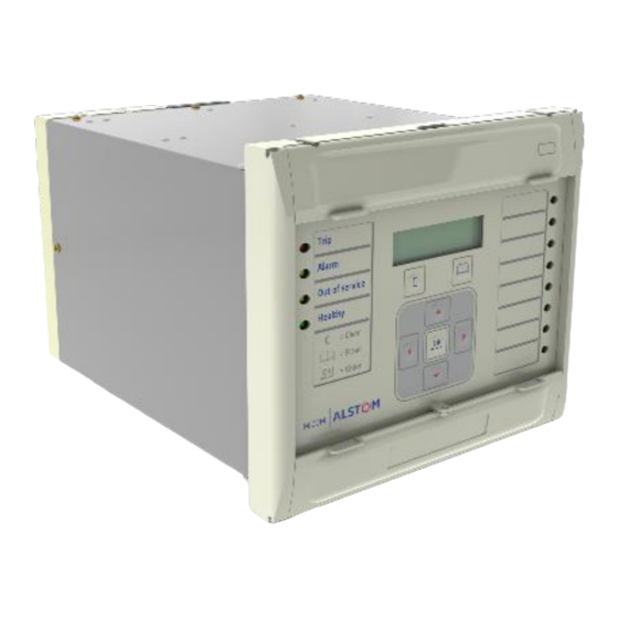
- Page 1 | AUTOMATION MiCOM ALSTOM P341 Interconnection Protection Relay Software Version: 36 & 71 Hardware Version: J Technical Data Sheet P341/EN TDS/F74 GRID...
- Page 2 The Alstom Grid logo and any alternative version thereof are trademarks and service marks of Alstom Grid. MiCOM is a registered trademark of Alstom Grid. All trade names or trademarks mentioned herein whether registered or not, are the property of their owners.
- Page 3 &'( " # %" " " % #& " " " & " "& & " " % " , #& " " "...
- Page 4 12 3 " " " " " " & " " # " " " % " & 12 3 "...
- Page 5 $ % & " !"# &...
- Page 6 ) * ' " & & # " " 30 +((( " " 30 00-)01- / 2-)33-...
- Page 7 " (+ ( * % & " ' " " " " " " " $& " " " ! !" () * & , & " " # *" " " " 0 " ! " " !" 3 "...
- Page 8 " '& $ "&) 10 ,2 " &' ()% ,! , 13 4 2 ,! , 1 ,2 &).&// ! ,# " "+ ! 7 8+ 8 - 7...
- Page 9 /* ( ,*9 " * + " " " % -" % ,/,0 -" % " " !! ) " " 5" " ! !8 " % $ + ' ! " !" $ & "" $ + ' $ 234 34%...
- Page 10 $ !" ! 6 !" #$ " ) < $ 8./ " # $% & &* &* ,-./ + " 01 21.3. 1&4 + 56 & 1 + " 0 31 " 0 31 " 0 31 &* $ 8./ ! 9 :** 1 2 3 31 121...
-
Page 11: Technical Data
Isolation to ELV level. Technical Data Rear communications port (RP1) Mechanical specifications EIA(RS)485 signal levels, two wire connections located on general purpose block, Design M4 screw. Modular platform relay, P341 in 40 TE or For screened twisted pair cable, multidrop, 60 TE case. -
Page 12: Power Supply
Optional rear redundant Ethernet Ratings connection for IEC 61850 AC measuring inputs 100 base FX interface Nominal frequency: 50 and 60 Hz (settable) Interface in accordance with IEEE802.3 and Operating range: 40 to 70 Hz IEC 61850 Wavelength: 1300 nm AC current Fiber: multi-mode 50/125 µm or 62.5/125 µm Nominal current (In): 1 and 5 A dual rated. -
Page 13: Output Contacts
Maximum loading = all digital inputs/outputs Power-up time energized Time to power up < 11 s. Quescent or 1/2 loading = 1/2 of all digital inputs/outputs energized Power supply interruption 3 power supply options: Battery backup (i) Vx: 24 to 48 V dc Front panel mounted (ii) Vx: 48 to 110 V dc, 40 to 100 V ac (rms) Type ½... -
Page 14: Environmental Conditions
250 A for 30 ms 30 A for 200 ms, dc resistive, 10,000 Rated voltage: 300 V operations (subject to the above limits of Make & Break Capacity: make / break capacity & rated voltage) 50 W resistive 10 A (*), dc inductive, 10,000 operations 62.5 W inductive (L/R = 50 ms) (subject to the above limits of make / break 2500 VA resistive (cos φ... -
Page 15: Electromagnetic Compatibility (Emc)
Tested as per (ii) Per ANSI/IEEE C37.90-1989 (reaffirmed IEC 60068-2-1: 2007 1994): -25°C storage (96 hours) 1.5 kV rms AC for 1 minute, across open -40°C operation (96 hours) contacts of normally open output relays. IEC 60068-2-2: 2007 1 kV rms AC for 1 minute, across open +85°C storage (96 hours) watchdog contacts. - Page 16 Surge withstand capability Conducted emissions Per IEEE/ANSI C37.90.1: 2002: Per EN 55022: 1998 Class A: 4 kV fast transient and 2.5 kV oscillatory 0.15 - 0.5 MHz, 79 dBμV (quasi peak) applied directly across each output contact, 66 dBμV (average) optically isolated input, and power supply 0.5 - 30 MHz, 73 dBμV (quasi peak) 60 dBμV circuit.
-
Page 17: Mechanical Robustness
Compliance demonstrated by Notified Body certificates of compliance. II (2) G Mechanical robustness Vibration test Per IEC 60255-21-1: 1996: Response Class 2 Endurance Class 2 Shock and bump Per IEC 60255-21-2: 1996: Shock response Class 2 Shock withstand Class 1 Bump Class 1 Seismic test Per IEC 60255-21-3: 1995:... -
Page 18: Protection Functions
Characteristic US: IEEE Protection functions C37.112…1996 * Under reference conditions Reverse/low forward/overpower Negative phase sequence overcurrent Accuracy Pick-up: Setting ±10% Reverse/Over Power Drop-off: Accuracy 0.95 of setting ±10% I2>Pick-up: Setting ±5% Low forward power Drop-off: I2> Drop-off: 0.95 x Setting ±5% 1.05 of setting ±10% Vpol Pick-up: Setting ±5% Angle variation Pick-up:... - Page 19 Wattmetric SEF accuracy Rate of change of frequency ‘df/dt’ P = 0 W Pick-up: ISEF> ±5% P > 0 W Pick-up: P> ±5% Accuracy P = 0 W Drop-off: (0.95 x ISEF>) ±5% Fixed Window P > 0 W Drop-off: 0.9 x P> ±5% Pick-up: Setting ±0.05 Hz/s or ±3% whichever Boundary accuracy: ±5% with 1°...
- Page 20 IDMT characteristic shape: ±2% or 50 ms CB fail whichever is greater DT operation: ±2% or 50 ms whichever is Timer accuracy greater Timers: ±2% or 40 ms whichever is greater Reset: <7 ms Reset time: <30 ms Repeatability: <1% Undercurrent accuracy Overvoltage Pick-up: ±10%...
- Page 21 Generator overfrequency System Split Pick-up: Setting ±0.01 Hz Accuracy Drop-off: (Setting -0.1 Hz) ±0.01 Hz Repeatability: <1% SS Phase Angle: Pick-up: (Setting+2°) ±1° Drop-off: (Setting+1°) ±1° Check Synch Repeatability: <1% Accuracy SS Undervoltage: Pick-up: Setting ±3% Drop-off: 1.02 x Setting CS1 Phase Angle: Repeatability: <1% Pick-up: (Setting-2°) ±1°...
-
Page 22: Irig-B And Real Time Clock
Other specifications Measurements CLI load resistance 0-1 mA: < 4 kΩ CLI load resistance 0-1 mA/0-20 mA/4 20 mA: Accuracy <300 Ω Current: 0.05…3 In: ±1% of reading Isolation between common input channels: Voltage: 0.05…2 Vn: ±5% of reading zero Power (W): 0.2…2 Vn, 0.05…3 In: ±5% of Isolation between input channels and case reading at unity power factor... - Page 23 IEC 61850 Ethernet data 100 Base FX Interface Transmitter optical characteristics (TA = 0°C to 70°C, VCC = 4.75 V to 5.25 V) Parameter Min. Typ. Max. Unit Output Optical Power BOL 62.5/125 µm, -16.8 -14 avg. NA = 0.275 Fiber EOL Output Optical Power BOL...
- Page 24 Settings, measurements and DST End Month: Jan/Feb/Mar/Apr records list /May/Jun/Jul/Aug/ Sept/Oct/Nov/Dec DST End Mins: 0 min…1425 min Settings list RP1 Time Zone: UTC/Local RP2 Time Zone: UTC/Local Global settings (system data) Tunnel Time Zone: UTC/Local Language: English/French/German/Spanish Frequency: 50/60 Hz Configuration Setting Group: Circuit breaker control...
- Page 25 Power CT and VT ratios Date and Time Main VT Primary: 100...1000000 V Description Main VT Sec'y: 80...140 Plant Reference (100/120 V) 320…560 V (380/480 V) Frequency C/S VT Primary: 100 V…1 MV Local Values: Primary/Secondary C/S VT Secondary: 80…140 V Remote Values: Primary/Secondary VN VT Primary (P342/3): 100…1000000 V...
- Page 26 RP2 Comms Mode: Custom IEC 60870 FT1.2 Opto Input 1: IEC 60870 10-Bit No parity (up to): RP2 Address: 0…255 Opto Input #. (# = max. opto no. fitted): RP2 InactivTimer: 1…30 mins Custom options allow independent RP2 Baud Rate: thresholds to be set per opto, from the same 9600/19200/38400 bits/s range as above.
-
Page 27: System Config
Protection functions Phase overcurrent (overcurrent) Phase O/C: Sub Heading I>1 Function: System config. Disabled Phase Sequence: Standard ABC/Reverse IEC S Inverse VT Reversal: No Swap/A-B Swapped/B-C IEC V Inverse Swapped/C-A Swapped IEC E Inverse CT Reversal: No Swap/A-B Swapped/B-C UK LT Inverse Swapped/C-A Swapped UK Rectifier C/S Input: A-N, B-N, C-N, A-B, B-C, C-A... - Page 28 The IEEE/US IDMT curves conform to the TD x S following formula: tRESET = in seconds (1 - M 2 ) ⎛ ⎞ Where: ⎜ ⎟ t = TD x (Ι/Ι s ) α - 1 ⎜ ⎟ ⎝ ⎠ Time dial setting for IEEE curves Constant...
- Page 29 IEC Curves Amercian Curves 1000 Curve 4 Curve 1 Curve 5 Curve 6 Curve 9 Curve 2 Curve 7 Curve 3 Curve 8 10.0 100.0 10.0 100.0 Current (Multiples of Is) Current (Multiples of Is) Curve 5 IEEE moderately inverse Curve 1 Standard inverse Curve 6...
- Page 30 IN1>1 K(RI): 0.10….10.00 Thermal overload IN1>1 IDG Time: 1.00...2.00 Thermal: Disabled/Enabled IN1>1 Reset Char.: DT/Inverse Thermal I>: 0.50…2.50 In IN1>1 tRESET: 0.00…100.00 s Thermal Alarm: 20..100% IN1>2 as IN>1 T-heating: 1…200 minutes IN1>3 Status: T-cooling: 1…200 minutes Disabled M Factor: 0…10 Enabled IN1>3 Directional: The thermal time characteristic is given by:...
- Page 31 failure occurs. ISEF> Char. Angle: -95...+95° IDG Is Setting Range ISEF> VNpol Set: 0.5...80.0 V (100/120 V) 2...320 V (380/480 V) WATTMETRIC SEF: PN> Setting: 0..20 In W (100/120 V) PN> Setting: 0 ..80 In W (380/480 V) IDG Time Setting Range Restricted earth fault (high impedance) I/IN>...
- Page 32 V>2 Voltage Set: Voltage protection 60…185 V (100/120 V) 240…740 V (380/480 V) Undervoltage V>2 Time Delay: 0.00…100.00 s V< Measur’t Mode: Phase-Phase The inverse characteristic is given by the Phase-Neutral following formula: V< Operate Mode: Any Phase (M - 1) Three Phase V<...
-
Page 33: Supervisory Functions
Supervisory functions Check sync CS1 Status: Disabled/Enabled CS1 Phase Angle: 5…90 Voltage transformer supervison CS1 Slip Control: VTS Status: Blocking/Indication None VTS Reset Mode: Manual/Auto Timer VTS Time Delay: 1.0…10.0 s Frequency VTS I> Inhibit: 0.08 In…32.0 In Both VTS I2> Inhibit: 0.05 In…0.50 In CS1 Slip Freq.: 0.01…1.00 Hz Negative phase sequence voltage (V2): CS1 Slip Timer: 0.00…99.00 s... -
Page 34: Input Labels
Fault Freq Lock: WV I< Alarm: Disabled/Enabled Alarm disabled WV I< Alarm Set: 0…4 mA Alarm enabled Wind Direction: Disabled, CLI1, CLI2, CLI3, Fault Freq Count: 1…9999 CLI4 Fault Freq Time: 0…9999 s Default Wind Dir: 0.0…360.0° Wind Dir Corr: -180.0…180.0° Wind Dir Min: 0.0…360.0°... - Page 35 CLI1 I< Alarm (4…20 mA input only): 3 Phase Vars*: -6000 Var…6000 Var Disabled/Enabled 3 Phase VA*: 0…6000 VA CLI1 I< Alm Set (4…20 mA input only): 3Ph Power Factor*: -1…1 0.0…4.0 mA Single Phase Active Power: CLI2/3/4 as CLI1 A Phase Watts*: B Phase Watts*: C Phase Watts*:...
-
Page 36: Measurements List
3 Phase VArs Measurements list 3 Phase VA NPS Power S2 Measurements 1 3Ph Power Factor Iϕ Magnitude ϕPh Power Factor Iϕ Phase Angle Independent power factor measurements for ϕ Per phase ( = A/A-1, B/B-1, C/C-1) current ϕ all three phases ( = A, B, C). - Page 37 Circuit breaker monitoring statistics CB Operations Total Iϕ Broken Cumulative breaker interruption duty ϕ on a per phase basis ( = A, B, C) CB Operate Time Reset CB Data: No/Yes. P341 Technical Data Sheet P341 Software versions 36 & 71J...
-
Page 38: Case Dimensions
CASE DIMENSIONS P1647ENd P341 case dimensions (40TE case) P341 case dimensions (60TE case) P341 Technical Data Sheet P341 Software versions 36 & 71J... -
Page 39: External Connection Diagrams
EXTERNAL CONNECTION DIAGRAMS Comms. options Px40 platform P341 Technical Data Sheet P341 Software versions 36 & 71J... - Page 40 Interconnection protection relay (40TE) for embedded generation using VEE connected VT's (8 I/P & 7 O/P) P341 Technical Data Sheet P341 Software versions 36 & 71J...
- Page 41 P4659ENa Interconnection protection relay (40TE) for embedded generation and sensitive power (8 I/P & 7 O/P) P341 Technical Data Sheet P341 Software versions 36 & 71J...
- Page 42 P4592ENb Interconnection protection relay (40TE) for embedded generation and check synchronizing (8 I/P & 7 O/P) P341 Technical Data Sheet P341 Software versions 36 & 71J...
- Page 43 Interconnection protection relay (40TE) for embedded generation (8 I/P & 7 O/P) P341 Technical Data Sheet P341 Software versions 36 & 71J...
- Page 44 Interconnection Protection Relay (40TE) for Embedded Generation (8 I/P & 11 O/P (4HB)) P341 Technical Data Sheet P341 Software versions 36 & 71J...
- Page 45 Dynamic line rating protection relay (40TE) (8 I/P & 7 O/P & CLIO) P341 Technical Data Sheet P341 Software versions 36 & 71J...
- Page 46 P2236ENa Interconnection protection relay (40TE) for embedded generation (8 I/P & 15 O/P) P341 Technical Data Sheet P341 Software versions 36 & 71J...
- Page 47 P2235ENa Interconnection protection relay (40TE) for embedded generation (16 I/P & 7 O/P) P341 Technical Data Sheet P341 Software versions 36 & 71J...
- Page 48 Interconnection protection relay (40TE) for embedded generation (12 I/P & 11 O/P) P341 Technical Data Sheet P341 Software versions 36 & 71J...
- Page 49 P4581ENa Dynamic line protection relay (60TE) (16 I/P & 16 O/P & CLIO) P341 Technical Data Sheet P341 Software versions 36 & 71J...
- Page 50 P4579ENb Interconnection protection relay (60TE) for embedded generation (24 I/P& 16 O/P) P341 Technical Data Sheet P341 Software versions 36 & 71J...
- Page 51 P4580ENa Interconnection protection relay (60TE) for embedded generation (16 I/P & 24 O/P) P341 Technical Data Sheet P341 Software versions 36 & 71J...
- Page 52 P4582ENa Interconnection protection relay (60TE) for embedded generation (16 I/P & 20 O/P (4HB)) P341 Technical Data Sheet P341 Software versions 36 & 71J...
- Page 53 P4583ENa Interconnection protection relay (60TE) (16 I/P & 12 O/P (4HB) & CLIO) P341 Technical Data Sheet P341 Software versions 36 & 71J...
- Page 54 P4586ENa Assembly P341 interconnection and DLR protection relay (40TE) (8 I/P & 7 O/P with optional I/P & O/P) P341 Technical Data Sheet P341 Software versions 36 & 71J...
- Page 55 P4656ENa Assembly P341 interconnection and DLR protection relay (40TE) (8 I/P & 7 O/P with optional CLIO) P341 Technical Data Sheet P341 Software versions 36 & 71J...
- Page 56 P4655ENa Assembly P341 interconnection and DLR protection relay (60TE) (16 I/P & 16 O/P with optional I/P & O/P) P341 Technical Data Sheet P341 Software versions 36 & 71J...
- Page 57 P4654ENa Assembly P341 interconnection and DLR protection relay (60TE) (16 I/P & 16 O/P with optional HB O/P) P341 Technical Data Sheet P341 Software versions 36 & 71J...
- Page 58 P4653ENa Assembly P341 interconnection and DLR protection relay (60TE) (16 I/P & 16 O/P with optional CLIO) P341 Technical Data Sheet P341 Software versions 36 & 71J...
- Page 59 Ordering options Information required with order P341 Interconnection Protection Relay P341 Vx Aux rating 24-48 Vdc 48-110 Vdc, 40-100 Vac 110-250 Vdc, 100-240 Vac I/n/Vn rating In=1 A/5 A, Vn=100/120 V (40 TE case) In=1 A/5 A Vn=380/480 V (40 TE case) In=1 A/5 A, Vn=100/120 V, with Check Sync VT Input (60 TE case only) In=1 A/5 A, Vn=380/480 V, with Check...
- Page 60 P341 Interconnection Protection Relay P341 Break) + CLIO** Note: HB = High Break Protocol options K-Bus MODBUS IEC 60870-5-103 (VDEW) DNP3.0 IEC 61850 + Courier via rear EIA(RS)485 port Mounting Panel Mounting Panel Mounting with Harsh Environment Coating Language options Multilingual - English, French, German, Spanish Multilingual - English, French, German,...
- Page 62 Alstom Grid Substation Automation Solutions Business www.alstom.com/grid Alstom Grid Worldwide Contact Centre online 24 hours a day: +44 (0) 1785 250 070 www.alstom.com/grid/contactcentre/...
Need help?
Do you have a question about the ALSTOM P341 and is the answer not in the manual?
Questions and answers