
Summary of Contents for L-3 TECHNOLOGIES ESI-500
- Page 1 Pilot’s Guide for the ESI-500 / MAG-500 Electronic Standby Instrument Sys Aviation Products...
- Page 3 L3 Aviation Products reserves the right to add, improve, modify, or withdraw functions, design modifications, or products at any time without notice. ESI-500 Product Part No. 9200-15000-0101 MAG-500 Product Part No. 9200-15500-0101 Document Part No. 0040-15000-01 (Revision E) © Copyright 2017...
- Page 4 Document Precedence This Pilot’s Guide provides general information about the operation of the ESI-500 and the optional MAG-500. Refer to your FAA-approved Airplane Flight Manual (AFM) and its flight manual supplements for information specific to your aircraft. If there is conflicting information between the AFM and this guide, the AFM takes precedence over this guide.
-
Page 5: Table Of Contents
Table of Contents Chapter 1 Description Introduction ..................1-1 Functional Description ..............1-2 Limitations ..................1-3 Specifications ................. 1-5 Chapter 2 Operation Introduction ..................2-1 Pilot Advisory .................. 2-1 Power On ..................2-1 Splash Screen ................2-2 Database Acknowledgement Screen ........2-2 Alignment .................. - Page 6 Table of Contents (cont.) Altitude.................... 3-6 Altimeter Tape ................3-6 Altitude Digital Readout ............. 3-7 Metric Altitude Digital Readout ..........3-7 Altitude Invalidity ............... 3-7 Vertical Speed ................3-8 Vertical Speed Invalidity ............3-8 Barometric Pressure Digital Display ..........3-8 Direction Display................
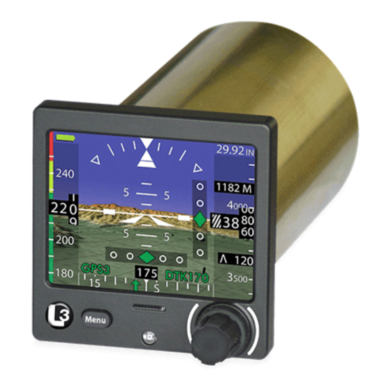
- Page 7 List of Illustrations Figure 1-1: ESI-500 ............... 1-1 Figure 2-1: Example of Attitude Aligning........2-2 Figure 2-2: Example of Normal Display and Synthetic Vision Display ..........2-3 Figure 3-1: Attitude Display Features ..........3-1 Figure 3-2: Airspeed Display Features .......... 3-3 Figure 3-3: V Awareness Color Bar Cues ........
- Page 8 List Of Abbreviations and Acronyms ° Degree °F Fahrenheit °C Celsius 3 Dimensional Airplane Flight Manual AFMS Airplane Flight Manual Supplement Altitude Attitude BATT Battery B/C or BC Backcourse Bright Calibration CHG INH Change Inhibited Course Data Configuration Module RTCA Document DTED Digital Terrain Elevation Data East...
- Page 9 List Of Abbreviations and Acronyms Navigation NM or nmi Nautical Miles NVIS Night Vision Imaging System Outside Air Temperature Outer Marker Beacon Part Number Altitude Above Ground Barometric Pressure for Standard Altimeter Setting Barometric Pressure for Local Altimeter Setting Required Real Time Clock Reduced Terrain Clearance Static Air Temperature...
- Page 10 This page intentionally blank viii Pilot’s Guide...
-
Page 11: Chapter 1 Description
MAG-500 Magnetometer. The system provides the flight crew with the display of attitude, slip, altitude, airspeed, and heading. The ESI-500 provides a means of setting barometric correction and adjusting the display brightness. In addition, functional upgrades are available for navigation information and the display of synthetic vision, including terrain and obstacles. -
Page 12: Functional Description
Description ESI-500 Functional Description The ESI-500 has interfaces for input and output of ARINC-429 data, discrete output, outside air temperature input, dimming bus, RS-485 interface between the ESI-500 and MAG-500, and an I C interface to the DCM-500. The battery pack automatically powers the ESI-500 and MAG-500 (if installed) without interruption upon loss of main input power. -
Page 13: Limitations
ESI-500 Description Functional Description (continued) If the aircraft does not already have a TAWS or Terrain alerting system installed, the Synthetic Vision should be configured to display alert shading (red and yellow) of the 3D terrain display, for caution and warning annunciations of terrain or obstacle impact. - Page 14 5. When the normal air data aiding source is lost for three minutes or if the Pitch or Roll value is greater than 35° for three minutes the ESI-500 can operate in an Attitude Degraded Mode, which means that the ESI-500 is not operating within the normal performance parameters.
-
Page 15: Specifications
ESI-500 Description Limitations (continued) 6. For installations with a MAG-500, the Heading Degraded operation occurs if the Roll value is greater than 11.5° for three minutes, or if the “ATT DEGRADED” indication is shown. The pilot is alerted to this degraded mode of operation by an amber “HDG DEGRADED”... - Page 16 Description ESI-500 Specifications (Continued) Slip Accuracy: Accuracy +/-2°. No turn rate, no standard turn bank angle. Release 1.1 the Range is +/- 12° Release 1.2 and greater the range is configurable at installation for +/- 7° or +/- 12°. Heading:...
- Page 17 Battery calibration once a year. Maintenance: Subject to requirements of 14 CFR 91.411. Service Life: The ESI-500 has unlimited service life. The battery has approximately 5 years of service life; provided that the procedures for maintenance are followed as detailed in the Battery Capacity Calibration Procedure.
- Page 18 Operation ESI-500 This page intentionally blank Pilot’s Guide...
-
Page 19: Chapter 2 Operation
System. Details for display elements are provided in Chapter 3. Pilot Advisory For ESI-500 functions that require data from an external source, the pilot should be familiar with the equipment that is providing the data. For example, which GPS provides the data for the Synthetic Vision and... -
Page 20: Splash Screen
The ATT ALIGNING message is shown in the center of the screen with a green progress bar below it. Refer to Figure 2-1. After alignment the ESI-500 enters normal operation. Refer to Figure 2-2. The alignment of attitude may require up to three minutes to complete depending on the motion of the aircraft. -
Page 21: Normal Operation
ESI-500 Operation Normal Operation An example of the ESI-500 in normal operation is shown in figure 2-2. Display features such as heading tape/readout, vertical speed readout, metric readout, and navigation information are configurable and shown for reference only. Figure 2-2: Example of Standard and Synthetic Vision Display... -
Page 22: Increase Display Brightness
Operation ESI-500 Increase Display Brightness When the pilot menu is not active, pressing and holding the Menu button will increase the display brightness. Use the pilot menu item ‘Set Brightness Offset’ to adjust the brightness level. Adjust Barometric Pressure Adjust barometric pressure by rotating the knob when the pilot menu is not active. -
Page 23: Table 2-1: Pilot Menu List
Alignment Activates the Alignment function. Battery Calibration Initiate the battery calibration function. Only available when aircraft power is removed from the ESI-500. System Status Display the status of the following battery informa- tion: state of charge, temperature, last calibration date, and next calibration due date. It also shows aircraft effectivity. -
Page 24: Shutdown Procedure
Operation ESI-500 Shutdown Procedure 1. Remove aircraft power from the ESI-500. (Battery backup is now functioning as indicated by battery icon in upper left side of display.) 2. Press Menu button. The BATT Shutdown menu item should be highlighted. 3. Press the knob to select BATT Shutdown. - Page 25 ESI-500 Operation • The calibration procedure can take up to 8 hours to complete. • To assure compliance with the temperature limits of the calibration, if performing the calibration procedure on aircraft the factory recommends, in regions with hot climates, performing the procedure during the cooler months of the year and in regions with cold climates, performing the procedure during the warmer months.
- Page 26 Operation ESI-500 5. Press the Menu button. 6. Rotate the knob until Battery Calibration is highlighted in the menu bar. 7. Press the knob to Confirm battery calibration. The following screen message appears: Battery Calibration In Progress... Auto-Off When Done Press Any Key to Abort 8.
-
Page 27: Database Update - 68Dc And 71Dc
• Reformatting the MicroSD card prior to saving the database file to the MicroSD card will ensure minimal load time to the ESI-500. It is the pilot/owners responsibility to make sure that the database they are using is accurate. - Page 28 Operation ESI-500 Database Update - 68DC and 71DC (continued) When loading the database files to a MicroSD card the Obstacle/ Navigation database must be named “68.bin” and the Terrain database must be named “71.bin”. Note - The database files must be copied to the root directory (i.e.
-
Page 29: Unusual Attitude Display Operation
To prevent potential damage to the ESI-500 and the MicroSD Card, the MicroSD card must be removed CAUTION from the card slot on the front of the ESI-500 during normal operation. Unusual Attitude Display Operation If an unusual attitude situation occurs navigation data and the barometric pressure digital display are removed from the display. -
Page 30: Attitude Degraded Operation
Operation ESI-500 Attitude Degraded Operation Attitude Degraded operation occurs when the normal air data aiding source is lost for three minutes, or if the Pitch or Roll value is greater than 35° for three minutes. The unit is able to continue displaying attitude information at a lesser performance. -
Page 31: Initiate Manual Alignment
ESI-500 Operation Initiate Manual Alignment Attitude Alignment can be manually activated using the Menu as follows: 1. Press the Menu button. 2. Rotate the knob until ATT Align is highlighted and press the knob. 3. Press the knob to Confirm. -
Page 32: Pre-Flight Instructions
6. Airspeed readout and TAS readout (if displayed) shows two white dashes until the minimum airspeed display value is reached. 7. Compare the information displayed on the ESI-500 with the primary display. • Attitude data is within +/- 1.0°. -
Page 33: In-Flight Instructions
3. Set the Navigation Mode (VOR/ILS or GPS) as needed, and set the course setting as needed. 4. During loss of aircraft power the ESI-500 will continue to display attitude, altitude, airspeed, and heading (MAG-500 installations only) for approximately 1 hour. External sensor inputs such as... - Page 34 Operation ESI-500 This page intentionally blank 2-16 Pilot’s Guide...
-
Page 35: Chapter 3 Display Features
This chapter provides an explanation of the display features and variations based on individual aircraft configuration options chosen at installation. This chapter provides details on the display features of the ESI-500. Included is information on available configuration options. Attitude Attitude information consists of an artificial horizon (sky (blue), ground (brown)), pitch ladder, roll indicator, and aircraft reference symbol. -
Page 36: Pitch Ladder
Display Features ESI-500 Pitch Ladder The pitch ladder scale is located in the center of the display with short horizontal lines positioned at +/- 2.5° and +/-7.5°, medium horizontal lines positioned every +/-5°, and long horizontal lines positioned every +/- 10°. The pitch ladder rotates around the aircraft reference symbol in relation to aircraft’s roll and scrolls up and down in response to the... -
Page 37: Airspeed
ESI-500 Display Features Airspeed Aircraft airspeed information is provided on the left-hand side of the display and consists of an airspeed tape, airspeed digital readout, and airspeed awareness color bar. See Figure 3-2. Configuration Options: • Airspeed units - knots or mph. -
Page 38: Airspeed Digital Readout
Display Features ESI-500 Airspeed Digital Readout The airspeed digital readout is displayed with rolling white digits on a black background. The maximum viewing range is 300 kts or 345 mph. The readout background and digits will change color to identify set airspeed cues. -
Page 39: Power On Awareness Color Bar Cues
ESI-500 Display Features High Speed Awareness Bar (Never Exceed Speed) Caution Range (Max Structural Cruising Speed) Normal Operating Airspeed Range (Optimum rate of climb with critical engine inoperative) (Maximum Flap Extended Speed) (Minimum control speed with critical engine inoperative) Safe Flap Operating... -
Page 40: Altitude
Display Features ESI-500 High Speed Awareness Bar (Maximum Operating Limit Speed) Normal Operating Airspeed Range (Optimum rate of climb with critical engine inoperative) (Maximum Flap Extended Speed) (Minimum control speed with critical engine inoperative) Safe Flap Operating Range (white) (Stall Speed in Specified Configuration) -
Page 41: Altitude Digital Readout
ESI-500 Display Features Figure 3-6: Altitude, Baro, and Vertical Speed Display Features Altitude Digital Readout The altitude digital readout is located in the center of the altitude tape and displays the current baro-corrected altitude in feet above mean sea level (MSL). -
Page 42: Vertical Speed
Display Features ESI-500 Vertical Speed If configured, the vertical speed digital readout is located on the altitude tape below the altitude digital readout. The vertical speed digital display range is from -9900 feet per minute (FPM) to +9900 FPM. See Figure 3-6. -
Page 43: Direction Display
ESI-500 Display Features Direction Display The Direction display will display either the aircraft magnetic heading or the aircraft magnetic track. The direction indicator is located at the bottom of the display between the airspeed and altitude tapes. The direction indicator consists of a tape and a digital readout. See Figure 3-7. -
Page 44: Direction Digital Readout
Display Features ESI-500 Direction Digital Readout The Direction readout is located above the direction tape. The tape has a range of 001° to 360° with a resolution of 1°. When track is configured, the readout digits are preceded with the direction source indicator ‘TRK’. -
Page 45: Air Temperature Display
Air Temperature from the air data system. “OAT” is displayed if the temperature is received from an analog OAT probe directly into the ESI-500. There are no static air corrections applied to this OAT signal The air temperature display can be activated using the Data Field Pilot Menu. -
Page 46: Navigation
Display Features ESI-500 Navigation If configured, navigation information is located in the lower portion of the display, above the heading tape. The Pilot menu is used to enable or disable navigation information from the display. Navigation data is removed when the Pilot menu is active, when aligning attitude, or if aircraft pitch has met or exceeded +30°... -
Page 47: Figure 3-10: Vor Display Features
ESI-500 Display Features Figure 3-10: VOR Display Features Figure 3-11: ILS/LOC Display Features Pilot’s Guide 3-13... -
Page 48: Selected Course
27 is 270°, then the selected course should be set to 270°.) The Selected Course affects only the Navigation display on the ESI-500, and does not control the NAV receiver’s OBS value (which is set from the CDI or HSI). -
Page 49: Selected Course Arrow
The color of the selected course arrow is the same as the navigation information. Note - When the GPS navigator is operating in ‘True North’ mode, the ESI-500 displays the true DTK or CRS value followed by a ‘T’, and the Selected Course arrow is removed from the Direction Tape.” Desired Track Desired Track is used for GPS navigation to provide the intended track to a waypoint. -
Page 50: To/From Indicator
Display Features ESI-500 TO/FROM Indicator The ‘TO’ / ‘FR’ indication is located to the right of the navigation source annunciator, in the lower left corner of the attitude display area. This indication is a VOR and GPS OBS function. Refer to Figures 3-10 and 3-12. -
Page 51: Marker Beacon
ESI-500 Display Features CRS Setting CRS Setting FROM FROM 95° 95° FROM 85° 85° Figure 3-13: Examples of VOR TO/FROM Transition Marker Beacon If the NAV receiver provides Marker Beacon information to the ESI- 500 the marker beacons are located towards the top right corner of the attitude display area. -
Page 52: Lateral Deviation Indicator
Figures 3-11. (E.g., for a localizer backcourse approach to runway 9, if the inbound course to Runway 9 is 090°, then the selected course should be set to the reciprocal value 270°.) The ESI-500 detects the aircraft direction (090°) is opposite from the course (270°), and indicates the ‘B/C’... -
Page 53: Vertical Deviation Indicator
ESI-500 Display Features Vertical Deviation Indicator The vertical deviation indicator is used for Localizer and GPS guidance. It is not shown when ILS BC mode is active, or for enroute GPS navigation, or GPS approaches providing lateral guidance only. It is centered on the right side of the attitude display area. -
Page 54: Figure 3-15: Synthetic Vision Display Features
Display Features ESI-500 The Synthetic Vision System and alerting functions use QNH (Barometric Pressure for Local altimeter Setting) operations. For QFE (Altitude Above Ground) operation the Synthetic Vision System must be disabled using the menu. It is recommended that the SynVis mode be disabled using the Pilot menu for QNE operations above transition altitudes (18,000 ft in the United States). -
Page 55: Grid Line Overlay
ESI-500 Display Features The synthetic vision function is available within 90 seconds of receiving position and orientation information. A synthetic vision acquiring message (SVS xx%) is shown on the display. See Figure 3-16 Figure 3-16: SVS % Grid line Overlay Grid lines can be displayed over the synthetic vision terrain. -
Page 56: Terrain Alert
Display Features ESI-500 Terrain Alert Two types of terrain alerts are shown on the synthetic vision display: caution alerts and warning alerts. The caution alert is shown when a hazard is detected within 60 seconds of the aircraft current flight path (see below). The object causing the alert will be highlighted in yellow on the synthetic vision display. -
Page 57: Obstacles Alert
ESI-500 Display Features Obstacles Alert Man-made obstacles are shown as black rectangular boxes with white outlines. The height of an obstacle symbol corresponds to the height of the obstacle, but the horizontal dimensions of the obstacle symbol correspond to an obstacle 150 ft wide by 150 ft deep regardless of the actual horizontal dimensions of the obstacle. -
Page 58: Synthetic Vision Terrain Alerting Function
(Hereafter the word “terrain” refers to “terrain or obstacles” unless indicated otherwise.) The ESI-500 Synthetic Vision Terrain Alerting function determines the terrain threat based on the phase of flight (Figure 3-21) and on the predicted terrain clearance compared to the required terrain clearance (Tables 3-1 &... -
Page 59: Reduced Required Terrain Clearance (Rtc)
(Figure 3-22 and Table 3-1). The ESI-500 issues a caution alert 60 seconds before the offending terrain and a warning alert 30 seconds before the offending terrain. -
Page 60: Imminent Terrain Impact (Iti)
(Figure 3-23 and Table 3-2). The ESI-500 issues a caution alert 60 seconds before the offending terrain and a warning alert 30 seconds before the offending terrain. -
Page 61: Synthetic Vision Invalidity
Panel Self Test page is active. This may cause ESI-500 SVS position to display at the simulated position, and possibly cause an Alert. Do not use the ESI-500 SVS function while the GPS is in the Panel Self Test Page. Pilot’s Guide... - Page 62 Display Features ESI-500 This page intentionally blank 3-28 Pilot’s Guide...
-
Page 63: Chapter 4 Messages And Indications
ESI-500 Messages and Indications CHAPTER 4 MESSAGES AND INDICATIONS Introduction Messages and indications provide functional status of a display feature or the unit in general. Messages or indications can be shown on the splash screen, system status screen (battery status), or on the normal operation screen. -
Page 64: Table 4-1: Indications And Display Conditions
Messages and Indications ESI-500 Table 4-1: Indications and Display Conditions CONDITION CAUSE/CORRECTIVE ACTION ‘ALT’ invalidity is shown Invalid altitude data is detected. on the right side of the 1. The air data sensor may need to screen with the altitude warm up. - Page 65 ESI-500 Messages and Indications Table 4-1: Indications and Display Conditions CONDITION CAUSE/CORRECTIVE ACTION When the unit is set to GPS data is missing or failed. display GPS Navigation. 1. Cycle power to the system. The DTK value is (---) with amber text and a 2.
- Page 66 Messages and Indications ESI-500 Table 4-1: Indications and Display Conditions CONDITION CAUSE/CORRECTIVE ACTION The amber ‘ATT DE- The unit shifts into the Attitude Degraded GRADED’ indication is Mode due to the following: shown in the upper left 1. A loss of air data for three minutes...
- Page 67 ESI-500 Messages and Indications Table 4-1: Indications and Display Conditions CONDITION CAUSE/CORRECTIVE ACTION Obvious heading differ- Heading error caused by bad input data. ence is observed between 1. Cycle power to the indicator and the the indicator and the external source device.
- Page 68 Messages and Indications ESI-500 Table 4-1: Indications and Display Conditions CONDITION CAUSE/CORRECTIVE ACTION The amber ‘SVS’ indi- The SVS indication is shown on the cation (Synthetic Vision screen for any of the following reasons: System) is shown on the •...
- Page 69 ESI-500 Messages and Indications Table 4-1: Indications and Display Conditions CONDITION CAUSE/CORRECTIVE ACTION Battery not available Battery operation (charge (amber). discharge) is not possible due to high temperature conditions or low battery voltage. 1. Check the Pilot Menu Battery Status.
-
Page 70: Battery Indications
Messages and Indications ESI-500 Battery Indications Battery indicators and messages are located on the top-left side of the display. The indicators provide details on the general state of charge (SOC), availability of the battery for discharge or charge, battery failure,... - Page 71 ESI-500 Messages and Indications Table 4-2: Battery Indications BATTERY INDICATORS DESCRIPTION Battery is discharging and has a SOC ≤ 65% but > 40%. Battery is discharging and has a SOC ≤ 40% but > 15%. Battery is discharging and has a SOC ≤...
- Page 72 Messages and Indications ESI-500 Table 4-2: Battery Indications BATTERY INDICATORS DESCRIPTION Battery charging is not possible due to a cell over voltage. The icon is removed if condition corrects. If icon continues to be seen after a cycling power to the unit a battery replacement may be required.
-
Page 73: Record Of Important Information
APPENDIX A Record Of Important Information Dealer Information Name______________________________________________________ Address____________________________________________________ City, State, Zip_______________________________________________ Telephone__________________________________________________ Equipment Information Date of Purchase____________________________________________ Installation Date_____________________________________________ Model Number______________________________________________ Part Number________________________________________________ Serial Number_______________________________________________ Mod Letter _________________________________________________ Release __________________________________________________ Aircraft Information Aircraft Make_______________________________________________ Aircraft Model_______________________________________________ Serial Number_______________________________________________ N Number__________________________________________________ Register this product online at: http://www.l3aviationproducts.com/warranty-registration/... -
Page 74: Notes
NOTES Pilot’s Guide... - Page 75 NOTES Pilot’s Guide...
- Page 76 Aviation Products L3 Aviation Products 5353 52 Street, S.E. Grand Rapids, MI USA 49512-9704 0040-15000-01 Telephone (800) 453-6600 Rev-E (02/28/2017) International (616) 949-6600 www.L3aviationproducts.com...
Need help?
Do you have a question about the ESI-500 and is the answer not in the manual?
Questions and answers