Table of Contents
Advertisement
Quick Links
Advertisement
Table of Contents

Related Manuals for Forward Lift CR4T

Summary of Contents for Forward Lift CR4T
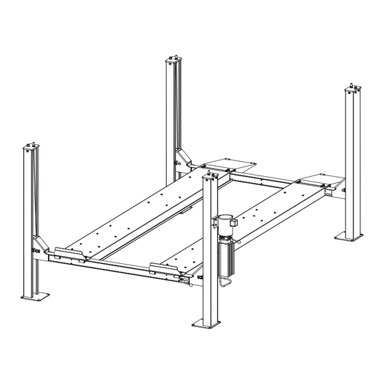
- Page 1 CR4T Installation Instructions Capacity 4082 kg (9000 lbs) 2041kg (4500 lbs) per axle Maximum Wheelbases: 3861mm (152") Minimum Wheelbase At Rated Capacity: 2515mm (99") © November 2014 by Vehicle Service Group. IN60034 All rights reserved. LP60034 CO9203 Rev. - 11/5/2014...
- Page 2 4731mm (186-1/4”) 4191mm (165”) 4070mm (160-1/4”) 4299mm (169-1/4”) 508mm (20”) 1000mm (39-3/8”) 508mm (20”) 772mm 4500mm (177-3/16”) (30-3/8”) 5337mm (210-1/8”) YOU WILL NEED A MIN. OF 15’ CLEARANCE IN REAR Fig. 1 TO INSTALL “T” ROD SPECIFICATIONS At full rise.......... 1962mm (77-1/4”) Baseplate to baseplate length ..
- Page 3 Safety If a forklift is not available a minimum of (4) people able to lift 57 kg (125 lbs) EACH will be needed to unload and assemble your lift. Wear work gloves, steel toed shoes, and safety glasses during the installation of your lift.
- Page 4 Step 1: Setting Runways: A.) If you haven't read previous pages, go back and do so now. B.) Place runways in desired location according to Fig. 3. Note: The runways weigh in excess of 182kg (400 lbs). Use a minimum of 4 people to move these runways. Attention! Use 4 People To Place Runways 57 kg...
- Page 5 Step 3: Installing Latch Bar: TOWARDS THE INSIDE OF THE LIFT. THE CROSSBEAM WITH A.) Remove Column Top Plate as shown, Fig. 4. THE FULL LENGTH SIDE COVER GOES TO THE OUTSIDE. THIS IS CRITICAL FOR CABLE INSTALLATION. B.) Install Rub Blocks as shown using M8 x 20 Socket Head Cap Screw in location shown.
- Page 6 Step 4: Reinstalling Column Top Plates: A.) Install (1) column top plate in each column, Fig. 6. Make sure latch bar jam nut is located far enough down the latch bar stud to allow you to fully insert the column top plate in the top of the column.
- Page 7 Step: 5: Runway Installation (columns not shown for clarity): C.) Using a mechanical device such as pulley or winch come A.) Use a minimum of (2) people to raise crossbeam assemblies along, fully extend hydraulic cylinder (located under runway). to first lock. D.) Being careful not to cross or pinch cables, install runway to B.) Remove inside short crossbeam covers, Fig.
- Page 8 IMPORTANT bar, Fig. 11. Run cables up each column keeping the cables on It is very important that the cables and the inside of the slack cable actuators, Fig. 10. You will need to sheaves in yoke assemblies get installed properly. Failure to do remove the Sheave Pins, Fig.
- Page 9 IMPORTANT PUSH COLUMNS UP TIGHT AGAINST RUB BLOCKS BEFORE DRILLING OR ANCHORING LIFT COLUMNS 2-1/4” 3-1/4” 4-1/4” 4-1/4” Clean hole. Drill holes using Tighten nut with 3/4” carbide Run nut down just Torque wrench to tipped masonary below impact section 110 ft.-lbs.
- Page 10 Step 8: Installing Power Unit: A.) Install power unit to power unit bracket, Fig. 13. Fig. 13 Ø8 LOCK WASHER SHOCK ABSORPTION WASHER Ø8 FLAT WASHER M8 NUT M8 x 25 BOLT Ø8 FLAT WASHER Step 9: Installing Hydraulic Hose: A.) Attach 90°...
- Page 11 Step 11: Electrical Service To Power Unit: IMPORTANT: Use separate circuit for each power unit. Protect Have a certified electrician run appropriate power supply to each circuit with time delay fuse or circuit breaker. For single phase 208-230V, use 20 amp fuse. Three phase 208-240V, use 20 motor.
- Page 12 Step 12: Raising Lift For Final Assembly Steps: CAUTION A.) Press the raise button on power unit, Fig. 15, and raise the runways up to a comfortable working height, approximately waist high. B.) Push down on the lowering valve to lower the runways onto locking latches.
- Page 13 Step 13: Inserting Latch Bar, Attaching Lock Cams And Latch D.) Install Latch Release Handle to Cam as shown, Fig. 17. Release Handle: E.) Install Linkages to Cam as shown, Fig. 18. Cam should sit A.) Remove outer crossbeam covers. straight up and down when linkages are tight.
- Page 14 Step: 14: Front Chock and Approach Ramp Installation: A.) Attach front chock as shown, Fig. 19. B.) Attach approach ramp with bar and cotter pins as shown, Fig. 20. Be sure to spread cotter pins after installation. M12 x 20 BOLT FRONT CHOCK Ø12 LOCKWASHER Ø12 FLAT WASHER...
- Page 15 Step: 16: Leveling your lift: D.) Adjust your cables next starting at the left rear column. Lower A.) Level the latch bars first. Make sure you have the lift off the the lift below the last slot in the latch bars so that the runways are ground and lowered onto the locking latches.
- Page 16 Forward Lift Phone: 800.445.5438 © 2011 Forward Lift; Forward Lift is a brand of Vehicle Service Group, 996 Industrial Drive Fax: 800.578.5438 A Dover Company. All rights reserved Unless otherwise indicated. Madison, IN. 47250 www.forwardlift.com Forward Lift, Vehicle Service Group, Dover, and all other trademarks...
Need help?
Do you have a question about the CR4T and is the answer not in the manual?
Questions and answers