Table of Contents
Advertisement
Quick Links
Download this manual
See also:
Owner's Manual
Advertisement
Table of Contents

Related Manuals for FUNAI F20LCTE


Summary of Contents for FUNAI F20LCTE
-
Page 1: Service Manual
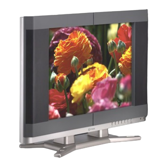
SERVICE MANUAL 20” COLOR LCD TELEVISION F20LCTE... -
Page 2: Table Of Contents
Consequently, Funai has not undertaken any such broad evaluation. Accordingly, a servicer who uses a service proce- dure or tool which is not recommended by Funai must first use all precau- tions thoroughly so that neither his safety nor the safe operation of the equipment will be jeopardized by the service method selected. -
Page 3: Specifications
SPECIFICATIONS <TUNER> ANT. Input ------------------- 75ohm Unbal., F type Reference Level ------------20Vp-p (CRT Green Cathode) Test Input Signal -----------400Hz 30% modulation Description Condition Unit Nominal Limit 1. Intermediate Freq. Picture 45.75 Sound 41.25 2. Color Killer Sens. CH-2 dBµV CH-10 dBµV CH-55 dBµV... -
Page 4: Important Safety Precautions
IMPORTANT SAFETY PRECAUTIONS Prior to shipment from the factory, our products are strictly inspected for recognized product safety and electrical codes of the countries in which they are to be sold. However, in order to maintain such compliance, it is equally important to implement the following precautions when a set is being serviced. - Page 5 ing is performed that involves B+, horizontal de- earth ground. If a voltage reading in excess of 1.0V flection or high voltage. Correct operation of the X- is obtained, remove and reinsert the AC power radiation protection circuits also must be recon- plug in the opposite polarity and again measure firmed each time they are serviced.
- Page 6 Precautions during Servicing 3) Align the lengths of the wires to be connected. In- sert the wires fully into the connector. A. Parts identified by the ( # ) symbol are critical for 4) Use the crimping tool to crimp the metal sleeve at safety.
- Page 7 Safety Check after Servicing Examine the area surrounding the repaired location Chassis or Secondary Conductor for damage or deterioration. Observe that screws, parts and wires have been returned to original posi- tions. Afterwards, perform the following tests and con- Primary Circuit Terminals firm the specified values in order to verify compliance with safety standards.
-
Page 8: Standard Notes For Servicing
STANDARD NOTES FOR SERVICING Circuit Board Indications How to Remove / Install Flat Pack-IC a. The output pin of the 3 pin Regulator ICs is indicat- 1. Removal ed as shown. With Hot-Air Flat Pack-IC Desoldering Machine: (1) Prepare the hot-air flat pack-IC desoldering ma- Top View Bottom View chine, then apply hot air to the Flat Pack-IC (about... - Page 9 3. The flat pack-IC on the CBA is affixed with glue, so With Soldering Iron: be careful not to break or damage the foil of each (1) Using desoldering braid, remove the solder from pin or the solder lands under the IC when remov- all pins of the flat pack-IC.
- Page 10 2. Installation (4) Bottom of the flat pack-IC is fixed with glue to the CBA; when removing entire flat pack-IC, first apply (1) Using desoldering braid, remove the solder from soldering iron to center of the flat pack-IC and heat the foil of each pin of the flat pack-IC on the CBA up.
- Page 11 Instructions for Handling Semiconductors Electrostatic breakdown of the semiconductors may occur due to a potential difference caused by electro- static charge during unpacking or repair work. 1. Ground for Human Body Be sure to wear a grounding band (1MΩ) that is prop- erly grounded to remove any static electricity that may be charged on the body.
-
Page 12: Cabinet Disassembly Instructions
CABINET DISASSEMBLY INSTRUCTIONS 1. Disassembly Flowchart REMOVAL REMOVE/ This flowchart indicates the disassembly steps for the LOC. PART Fig. *UNHOOK/UNLOCK/ cabinet parts and the CBA in order to gain access to Note RELEASE/UNPLUG/ item(s) to be serviced. When reassembling, follow the DESOLDER steps in reverse order. - Page 13 (S-1) (S-1) (S-2) (S-1) (S-1) (S-1) [1] Rear Cabinet (S-1) Fig. D1 L0305DC...
- Page 14 [11] LED B CBA [14] Front Cabinet (S-13) [12] Speaker L (S-14) (S-14) [10] LED A CBA (S-12) (S-10) (S-11) [8] Function CBA [9] IR Sensor CBA (S-15) [7] Liquid Cyrstal Panel (S-15) [6] LCD Holder [13] Speaker R (S-9) (S-8) [5] LCD Main CBA Unit [2] Jack Holder...
- Page 15 TV Cable Wiring Diagram LED B CBA To Liquid Crystal Panel CLN81 To Liquid Crystal Panel CN310A CN311A CN312A LCD Main CN101B CN102B CN103B CBA Unit CN51 CN53 CN101A CN102A CN103A CN81 CN481 CLN481 CN801 Main CBA CN80 CN802 To Liquid Crystal Panel CLN80 To Speaker To Speaker...
-
Page 16: Electrical Adjustment Instructions
ELECTRICAL ADJUSTMENT INSTRUCTIONS 1. Initial Setting General Note: "CBA" is abbreviation for "Circuit Board Assem- General bly." Enter the Service mode. NOTE: Electrical adjustments are required after replacing Set the each initial data as shown on tabel 1 below. circuit components and certain mechanical parts. It is important to perform these adjustments only after all Table 1: Initial Data repairs and replacements have been completed. - Page 17 2. +B Adjustment BUTTON DATA ITEM (on the service Purpose: To obtain correct operation. VALUE remote control) Symptom of Misadjustment: The picture is dark and NORMAL the unit does not operate correctly. DARK Test Point Adj. Point SAIDO TP401 (+B) VR649 C-SAIDO TP300 (GND)
-
Page 18: White Balance Adjustment
4. Flicker Adjustment The following adjustment normally are not attempted in the field. Only when replacing the Adjustment Point: VR201 (LCD Main CBA Unit) LCD Panel then adjust as a preparation. LCD Main CBA Unit 5. White Balance Adjustment Purpose: To mix red, green and blue beams correctly VR201 for pure white. -
Page 19: Block Diagrams
BLOCK DIAGRAMS System Control Block Diagram L0305BLS... - Page 20 IF/Video Block Diagram L0305BLIF...
- Page 21 Audio Block Diagram L0305BLA...
- Page 22 LCD Block Diagram L0305BLLCD...
- Page 23 Power Supply Block Diagram L0305BLP...
- Page 24 LCD Backlight Block Diagram L0305BLLB...
-
Page 25: Schematic Diagrams / Cba's And Test Points
SCHEMATIC DIAGRAMS / CBA'S AND TEST POINTS Standard Notes Many electrical and mechanical parts in this chassis have special characteristics. These characteristics often pass unnoticed and the protection afforded by them cannot necessarily be obtained by using replacement compo- nents rated for higher voltage, wattage, etc. Replacement parts that have these special safety characteristics are identified in this manual and its supplements;... - Page 26 LIST OF CAUTION, NOTES, AND SYMBOLS USED IN THE SCHEMATIC DIAGRAMS ON THE FOLLOWING PAGES: 1. CAUTION: FOR CONTINUED PROTECTION AGAINST RISK OF FIRE, REPLACE ONLY WITH SAME TYPE_A,_V FUSE. ATTENTION: UTILISER UN FUSIBLE DE RECHANGE DE MÊME TYPE DE_A,_V. 2.
- Page 27 Main 1/4 Schematic Diagram MAIN 1/4 Ref No. Position IC502 IC503 IC504 IC505 TRANSISTORS Q501 Q502 Q503 Q504 Q505 Q506 Q507 Q508 Q509 Q510 Q511 Q512 Q513 CONNECTORS CN51 CN52 CN53 CN80 CLN80 CN81 CLN81 CN101A CN102A L0305SCM1...
- Page 28 Main 2/4 Schematic Diagram VIDEO SIGNAL AUDIO SIGNAL MAIN 2/4 Ref No. Position IC11 IC851 IC852 IC871 TRANSISTORS Q709 TEST POINT TP300 L0305SCM2...
- Page 29 Main 3/4 Schematic Diagram VIDEO SIGNAL AUDIO SIGNAL MAIN 3/4 Ref No. Position IC781 IC801 TRANSISTORS Q701 Q702 Q703 Q704 Q705 Q706 Q707 Q708 Q791 Q802 Q803 CONNECTORS CN103A CN801 CN802 L0305SCM3...
- Page 30 Main 4/4 Schematic Diagram CAUTION ! NOTE : CAUTION: FOR CONTINUED PROTECTION AGAINST RISK Fixed voltage ( or Auto voltage selectable ) power supply circuit is used in this unit. The voltage for parts in hot circuit is OF FIRE, REPLACE ONLY WITH SAME TYPE 4A, 125V FUSE. If Main Fuse (F601) is blown, check to see that all components in the power supply measured using hot GND as a ATTENTION: UTILISER UN FUSIBLE DE RECHANGE DE...
- Page 31 Inverter Schematic Diagram INVERTER Ref No. Position IC401 TRANSISTORS Q403 Q405 Q411 Q412 Q431 Q432 Q433 Q434 Q435 Q436 Q461 Q462 Q463 Q464 Q465 Q466 CONNECTORS CN430 CN440 CN450 CN460 CN470 CN480 CN481 7-11 7-12 L0305SCI...
- Page 32 Function Schematic Diagram 7-13 7-14 L0305SCF...
- Page 33 IR Sensor Schematic Diagram 7-15 7-16 L0305SCIR...
- Page 34 LCD Main 1/3 Schematic Diagram VIDEO SIGNAL LCD 1/3 Ref No. Position IC333 CONNECTORS CN102B CN310A CN311A 7-17 7-18 L0305SCLCD1...
- Page 35 LCD Main 2/3 Schematic Diagram VIDEO SIGNAL LCD 2/3 Ref No. Position IC151 IC171 TRANSISTORS Q101 Q102 Q103 Q104 Q105 Q106 Q107 Q108 Q109 Q151 CONNECTORS CN103B CN104 CN105 7-19 7-20 L0305SCLCD2...
- Page 36 LCD Main 3/3 Schematic Diagram LCD 3/3 Ref No. Position IC201 IC202 IC203 IC204 IC205 TRANSISTOR Q201 CONNECTORS CN101B CN312A VARIABLE RESISTOR VR201 7-21 7-22 L0305SCLCD3...
- Page 37 Main CBA Top View CAUTION ! CAUTION: FOR CONTINUED PROTECTION AGAINST RISK BECAUSE A HOT CHASSIS GROUND IS PRESENT IN THE POWER Fixed voltage ( or Auto voltage selectable ) power supply circuit is used in this unit. OF FIRE, REPLACE ONLY WITH SAME TYPE 4A, 125V FUSE. SUPPLY CIRCUIT, AN ISOLATION TRANSFORMER MUST BE USED.
- Page 38 Main CBA Bottom View CAUTION ! CAUTION: FOR CONTINUED PROTECTION AGAINST RISK BECAUSE A HOT CHASSIS GROUND IS PRESENT IN THE POWER Fixed voltage ( or Auto voltage selectable ) power supply circuit is used in this unit. OF FIRE, REPLACE ONLY WITH SAME TYPE 4A, 125V FUSE. SUPPLY CIRCUIT, AN ISOLATION TRANSFORMER MUST BE USED.
- Page 39 Function CBA Top View IR Sensor CBA Top & Bottom View BL0300F01011-3 BL0300F01011-2 LED-A CBA Top & Bottom View Function CBA Bottom View BL0300F01011-4 LED-B CBA Top & Bottom View BL0300F01011-2 BL0300F01011-5 7-27 7-28...
- Page 40 Inverter CBA Top View INVERTER CBA Ref No. Position IC401 TRANSISTORS Q403 Q405 Q411 Q412 Q431 Q432 Q433 Q434 Q435 Q436 Q461 Q462 Q463 Q464 Q465 Q466 CONNECTORS CN430 CN440 CN450 CN460 CN470 CN480 CN481 VARIABLE RESISTOR VR401 Inverter CBA Bottom View 7-29 7-30 BL0300F01021...
-
Page 41: Waveforms
WAVEFORMS WF1 ~ WF12 = Waveforms to be observed at Waveform check points. (Shown in Schematic Diagram.) Input: NTSC Color Bar Signal (with 1kHz Audio Signal) 1DIV: 1.0V 10 s 1DIV: 1.0V 10 s 1DIV: 200mV 20 s Pin 5 of CN310A Pin 48 of CN310A Pin 19 of CN103A 1DIV: 1.0V 20ns... -
Page 42: Wiring Diagram
WIRING DIAGRAM L0305WI... - Page 43 EXPLODED VIEWS Cabinet A35-1 LED B CBA SP804 A35-2 SP802 LCD1 CLN311 CLN310 CLN312 LCD Main CBA Unit LED A CBA Function CBA SP803 IR Sensor CBA SP801 Main CBA Inverter CBA AC601 See Electrical Parts List for parts with this mark. 10-1 10-2 L0305CEX...
- Page 44 Packing Some Ref. Numbers are not in sequence. Tape Tape Packing Tape Packing Tape Packing Tape 10-3 L0305PEX...
-
Page 45: Mechanical Parts List
MECHANICAL PARTS LIST PRODUCT SAFETY NOTE: Products marked with a # Ref. No. Description Part No. have special characteristics important to safety. Before ACCESSORIES replacing any of these components, read carefully the BAG POLYETHYLENE 235X365XT0.03 0EM408420 product safety notice in this service manual. Don't OWNER'S MANUAL L0305UF 1EMN20121 degrade the safety of the product through improper ser-... -
Page 46: Electrical Parts List
ELECTRICAL PARTS LIST PRODUCT SAFETY NOTE: Products marked with a Ref. No. Description Part No. # have special characteristics important to safety. CHIP CERAMIC CAP .(1608) CH J 47pF/50V CHD1JJ3CH470 Before replacing any of these components, read care- C481 ELECTROLYTIC CAP . 220µF/25V M or CE1EMASTL221 fully the product safety notice in this service manual. - Page 47 Ref. No. Description Part No. Ref. No. Description Part No. ELECTROLYTIC CAP . 2200µF/6.3V M CE0KMZNTL222 C803 FILM CAP .(P) 0.1µF/50V J or CMA1JJS00104 C638 ELECTROLYTIC CAP . 2200µF/25V M or CE1EMZPDL222 FILM CAP .(P) 0.1µF/50V J CA1J104MS029 ELECTROLYTIC CAP . 2200µF/25V M CE1EMZNTL222 C804 FILM CAP .(P) 0.1µF/50V J or...
- Page 48 Ref. No. Description Part No. Ref. No. Description Part No. ZENER DIODE MTZJT-773.6B or QDTB0MTZJ3R6 D542 SWITCHING DIODE 1SS133(T-77) or QDTZ001SS133 ZENER DIODE DZ-3.6BSBT265 NDTB0DZ3R6BS SWITCHING DIODE 1N4148 NDTZ001N4148 D483 PCB JUMPER D0.6-P5.0 JW5.0T D605 DIODE 1N5397-B or NDLZ001N5397 D484 PCB JUMPER D0.6-P5.0 JW5.0T RECTIFIER DIODE ERB12-06...
- Page 49 Ref. No. Description Part No. Ref. No. Description Part No. ZENER DIODE DZ-8.2BSBT265 NDTB0DZ8R2BS TRANSISTORS D702 ZENER DIODE MTZJT-778.2B or QDTB0MTZJ8R2 TRANSISTOR 2SC2785(F) or QQSF02SC2785 ZENER DIODE DZ-8.2BSBT265 NDTB0DZ8R2BS TRANSISTOR 2SC2785(H) or QQSH02SC2785 D703 ZENER DIODE MTZJT-778.2B or QDTB0MTZJ8R2 TRANSISTOR 2SC2785(J) or QQSJ02SC2785 ZENER DIODE DZ-8.2BSBT265 NDTB0DZ8R2BS...
- Page 50 Ref. No. Description Part No. Ref. No. Description Part No. TRANSISTOR 2SC3331(T)-AANP or 2SC3331TZ TRANSISTOR 2SC2785(J) or QQSJ02SC2785 TRANSISTOR 2SC3331(U)-AANP or 2SC3331UZ TRANSISTOR KTC3199(GR) or NQS10KTC3199 TRANSISTOR 2SC1815-GR(TPE2) QQS102SC1815 TRANSISTOR KTC3198(GR) or NQS40KTC3198 Q506 TRANSISTOR 2SA1175(F) or QQSF02SA1175 TRANSISTOR 2SC3331(T)-AANP or 2SC3331TZ TRANSISTOR KTA1267(GR) or NQS10KTA1267...
- Page 51 Ref. No. Description Part No. Ref. No. Description Part No. CHIP RES.(1608) 1/10W J 10k Ω TRANSISTOR 2SC1815-GR(TPE2) QQS102SC1815 RRXAJR5Z0103 CHIP RES.(1608) 1/10W J 10k Ω Q708 TRANSISTOR 2SC2785(F) or QQSF02SC2785 RRXAJR5Z0103 CARBON RES. 1/4W J 4.7k Ω TRANSISTOR 2SC2785(H) or QQSH02SC2785 RCX4JATZ0472 CHIP RES.(1608) 1/10W J 1 Ω...
- Page 52 Ref. No. Description Part No. Ref. No. Description Part No. CARBON RES. 1/4W J 390k Ω CHIP RES.(1608) 1/10W J 75 Ω R609 RCX4JATZ0394 R754 RRXAJR5Z0750 CHIP RES.(1608) 1/10W J 18k Ω R610 PCB JUMPER D0.6-P5.0 JW5.0T R755 RRXAJR5Z0183 METAL OXIDE FILM RES. 2W J 0.68 Ω or CHIP RES.(1608) 1/10W J 1k Ω...
- Page 53 Ref. No. Description Part No. Ref. No. Description Part No. CHIP RES.(1608) 1/10W J 180k Ω R857 RRXAJR5Z0184 JS602 PCB JUMPER D0.6-P10.0 JW10.0T CHIP RES.(1608) 1/10W J 2.2k Ω R893 RRXAJR5Z0222 JS603 PCB JUMPER D0.6-P7.5 JW7.5T MISCELLANEOUS JS604 PCB JUMPER D0.6-P10.0 JW10.0T JS636 PCB JUMPER D0.6-P7.5...
- Page 54 Ref. No. Description Part No. Ref. No. Description Part No. CARBON RES. 1/4W J 1k Ω RCX4JATZ0102 C438 CERAMIC CAP .(AX) B K 0.047µF/50V CA1J473TU011 CARBON RES. 1/4W J 2.2k Ω RCX4JATZ0222 C439 CERAMIC CAP . SL J 22pF/3KV CCD3FJASL220 MISCELLANEOUS C440 CERAMIC CAP .(AX) B K 0.047µF/50V...
- Page 55 Ref. No. Description Part No. Ref. No. Description Part No. D444 SWITCHING DIODE 1SS133(T-77) or QDTZ001SS133 TRANSISTOR 2SC3331(U)-AANP or 2SC3331UZ SWITCHING DIODE 1N4148 NDTZ001N4148 TRANSISTOR 2SC1815-GR(TPE2) QQS102SC1815 D445 SWITCHING DIODE 1SS133(T-77) or QDTZ001SS133 Q434 TRANSISTOR 2SC2785(F) or QQSF02SC2785 SWITCHING DIODE 1N4148 NDTZ001N4148 TRANSISTOR 2SC2785(H) or QQSH02SC2785...
- Page 56 Ref. No. Description Part No. Ref. No. Description Part No. TRANSISTOR 2SC1815-GR(TPE2) QQS102SC1815 POWER RELAY RPEF-12-901 or MRNDC12KB002 RESISTORS RELAY ALKS321 MRNDC12MS013 CHIP RES.(1608) 1/10W J 10k Ω T430 INVERTER TRANS ETJV16ZE1TAC LTZ00CPMS002 R408 RRXAJR5Z0103 CHIP RES.(1608) 1/10W J 10k Ω T440 INVERTER TRANS ETJV16ZE1TAC LTZ00CPMS002...
- Page 57 F20LCTE L0305UF 2004-09-21...
Need help?
Do you have a question about the F20LCTE and is the answer not in the manual?
Questions and answers