
Summary of Contents for Warn Industries PullzAll 885002
- Page 1 SERVICE GUIDE WARN PULLZALL 230v AC P/N 885002, 885003 & 885004 REPAIR / REPLACEMENT INSTRUCTIONS TROUBLE SHOOTING GUIDE 987605A1 Page 1 of 49...
- Page 2 WARNING This guide identifies potential hazards and has important safety messages that help you and others avoid personal injury or death. WARNING and CAUTION are signal words that identify the level of hazard. These signal words mean: WARNING signals a hazard that may cause serious injury or death, if you do not follow recommendations.
-
Page 3: Table Of Contents
CONTENTS 1. GENERAL DESCRIPTION 2. DISASSEMBLY AND ASSEMBLY 2.1. Suggested Tools 2.2. Housing 2.3. Gear Train Assembly 2.4. Motor 2.5. Wire Rope Assembly 2.6. Safety Hook 2.7. Tail Hook 2.8. Drum Assembly 2.9. Wiring Diagrams 2.10. Filter Assembly 2.11. Torque Specifications 3. -
Page 4: General Description
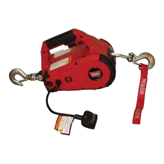
1. GENERAL DESCRIPTION The PullzAll is a powerful, lightweight, easy-to-use handheld electric tool with the ability to lift or pull up to 1,000 lbs / 454 kg. A strong Motor and Variable Speed Trigger Switch for power in and power out operation, Wire Rope and Clasp Hook will allow you to move heavy items into place smoothly and precisely. - Page 5 Convenient Forward/Reverse Switch Handle with Trigger for Variable Speed Control 15’ of 7/32” Wire Rope with Industrial Electronic Load Grade Hook Limiter with LED Indicator for Operator Feedback Versatile Swivel Anchor Hook 1000 lbs/454 Kg Lifting/Pulling Capacity Runs on 230v AC Power 987605A1 Page 5 of 49...
-
Page 6: Disassembly And Assembly
2. DISASSEMBLY AND ASSEMBLY 2.1 SUGGESTED TOOLS 1. Hammer 2. Snap ring plier 3. Allen key set 4. Screw driver 5. Cutting plier 6. Pin remover (Punch) 7. Insulation tape 8. Gloves 987605A1 Page 6 of 49... -
Page 7: Housing
2.2 HOUSING Before opening the Housing follow the below instructions: Power Cord Always unplug the product while rigging, when not in use or during maintenance and cleaning. 2.2.1 REMOVAL OF HOUSING 1. Remove the screws (#6 x .75), Qty 7 from Handle. - Page 8 3. Keep the assembly on the work bench facing the cover in the direction as shown in the figure. 4. Remove the Plastic Housing -left hand from the assembly as shown in the figure. 5. Remove the Main Chassis from the Plastic Housing - right hand and place it on the work bench.
- Page 9 2.2.2 ASSEMBLY OF HOUSING 1. Install the Main Chassis in the Plastic Housing - right hand as shown in the figure. 2. Install the Plastic Housing -left hand on the assembly as shown in the figure. 3. Flip the assembly as show in the figure. 987605A1 Page 9 of 49...
- Page 10 4. Install the screws (#8 X 1.25), Qty 6 from the main body of the Housing 5. Install the screws (#6 x .75), Qty 7 near Handle Note: When replacing the Housings with a Housing Service kit, be sure to affix all appropriate labels from the service kit onto the new housings, using the housings being replaced as a guide for placement of your new labels.
-
Page 11: Gear Train Assembly
2.3 GEAR TRAIN ASSEMBLY • If the gear sets are worn or damaged, the entire PullzAll must be replaced, no replacement parts are available. 2.3.1 GEAR TRAIN ASSEMBLY REMOVAL 1. Remove Retaining Ring from Idler Gear 2. Remove Wear Washer from Idler Gear 3. - Page 12 4. Remove Helical Gear from Gear Housing. 5. Remove 3 Cap Screws (#3 x .75) from Gear Housing through Left side Bracket of Chassis assembly. 6. Remove Gear Housing from left side Bracket of Chassis assembly. 7. Remove Carrier Assembly from Ring Gear.
- Page 13 8. Remove Ring Gear 51 T from left side Bracket of Chassis assembly. 2.3.2 GEAR TRAIN REASSEMBLY 1. Install Gear Train assembly after installation of Motor assembly. 2. Insert Ring Gear 51 T on Left side Bracket of Chassis assembly as shown in the figure.
- Page 14 3. Install Ring Gear 48T and Carrier Assembly in Gear Housing . 4. Install Gear Housing on Left side Bracket of Chassis assembly. 5. Install 3 Cap Screws (#3 x .75) in Gear Housing through Left side Bracket of Chassis assembly. 6.
- Page 15 7. Install Wear Washer on Helical Gear Press. 8. Install Retaining Ring on Helical Gear Press. 9. Install Idler Gear on Gear Housing. 10. Install Wear Washer and Retaining Ring on Idler Gear. 987605A1 Page 15 of 49...
- Page 16 2.3.3 INSPECTION OF GEAR TRAIN 1. Check each Idler Gear to make sure that all teeth are present in good condition. 2. Check each Sun Gear to make sure all teeth are present and in good condition. 3. Check each side of each Sun Gear to make sure there are no grooves from wear. Replace the Gear Set if worn.
-
Page 17: Motor
2.4 MOTOR 987605A1 Page 17 of 49... - Page 18 2.4.1 REMOVAL OF MOTOR Before removing the Motor follow the instructions given below: 1. Remove the Gear Train assembly. 2. Remove the 2 screws (#8 x 0.75) from Chassis assembly 3. Remove the left side cap screw and nut from Hawse Fairlead assembly. 987605A1 Page 18 of 49...
- Page 19 4. Remove cap screw from Chassis assembly as shown in the figure. 5. Remove Left side Bracket from Chassis assembly. 6. Remove Motor assembly from Chassis assembly after removal of Wiring leads. 987605A1 Page 19 of 49...
- Page 20 2.4.2 ASSEMBLY OF MOTOR 1. Connect all Wire leads from Motor assembly and install in to Chassis assembly as shown in the figure. 2. Install Left side Bracket on Chassis assembly as shown in the figure. 3. Install cap screw in Chassis assembly as shown in the figure.
- Page 21 4. Install the left side cap screw and nut from Hawse Fairlead assembly. Install 2 screws (#8 x 0.75) in Chassis assembly. 2.4.3 MOTOR INSPECTION • Visual inspection. • While assembling the Motor ensure that, Motor has been properly placed inside the End Housing and the screw had been properly tightened.
-
Page 22: Wire Rope Assembly
2.5 WIRE ROPE ASSEMBLY 2.5.1 REMOVAL OF WIRE ROPE Note: Prior to disassembly: 1. Spool out all Wire Rope. 2. Use of gloves is recommended while handling frayed or damaged Wire Rope. 3. Unplug unit before disassembly. Tasks: Disassemble the Drum and Wire Rope. 1. - Page 23 3.Use the Pin remover (punch) to remove the Wire Rope and Stop Button from the Drum. 4. Straighten the bent Rope and pull the Rope out of Drum hole as shown in fig. 5. Remove the Hawse Fairlead from the Bracket of the Chassis.
- Page 24 2.5.2 ASSEMBLY OF WIRE ROPE 1. Assemble the Hawse Fairlead to the Bracket of the Chassis. 2.Tighten the cap screws with Allen key and opened end wrench. 3. Keep the insulation tape to the edge of the Wire Rope. 987605A1 Page 24 of 49...
- Page 25 4. Insert the Wire Rope into the Drum through the Hawse Fairlead. 5. Pull the wire from the other end of the Drum hole. 6. Bend the Wire Rope and insert in to the same hole in the direction as shown in the figure.
- Page 26 8. Support one edge of the Wire and pull the other Wire as shown in the figure. 9. Verify Wire Rope stop button is inserted into the loop as shown before pulling the Wire Rope tight 10. Hit wire rope loop with a hammer, so that the Wire Rope will be pushed in to the rope retention hole.
- Page 27 12. Check from the other side of the Drum whether the Wire Rope is perfectly assembled to the Drum. 2.5.3 INSPECTION OF WIRE ROPE • Inspect the Wire Rope for signs of wear or damage. Worn and damaged parts must be replaced.
-
Page 28: Safety Hook
2.6 SAFETY HOOK 2.6.1 REMOVAL OF SAFETY HOOK To remove Safety hook follow the below instructions: 1. First straighten the bent end of the Cotter Pin by using Cutting plier and then pull out the Cotter Pin by holding head of the Cotter Pin with the help of cutting plier from the Pin. - Page 29 2. Remove the Pin from the Hook and Rope. 3. Remove the Safety Hook from Wire Rope 2.6.2 ASSEMBLY OF SAFETY HOOK To Reassemble Safety Hook follow the below instructions: 1.Place the Safety Hook and align the mounting holes with the loop of the Wire Rope 987605A1 Page 29 of 49...
- Page 30 2. Insert the Pin through Safety Hook and Wire Rope loop. 3. Insert the Cotter Pin inside the hole of the Pin and bend the ends of the Cotter Pin with the help of Cutting pliers. 2.6.3 INSPECTION • Inspect the Hook for signs of wear and damage. •...
-
Page 31: Tail Hook
2.7 TAIL HOOK Original Tail Hook Assy Generation Tail Hook Assy Service Part Tail Hook Assy 987605A1 Page 31 of 49... - Page 32 2.7.1 REMOVAL OF TAIL HOOK To remove Tail Hook follow the below instructions: 1.Remove bolt and nut from the Chassis assembly through Tail Hook. 2.Loosen the cap screw with Allen key before removing the Tail Hook and Spacer Pin from Chassis assembly. 987605A1 Page 32 of 49...
- Page 33 2.7.2 ASSEMBLY OF TAIL HOOK To Reassemble Original Tail Hook follow the below instructions: 1.Tight the cap Screw after place Tail Hook and Spacer Pin between the Brackets holes. 2.Assemble the bolt and nut. 987605A1 Page 33 of 49...
- Page 34 To Reassemble the Second Generation Tail Hook follow the instructions 1.Place Spacer Bracket in Chassis assembly with cap screw and then apply the torque. 2.Take the Tail Hook and align the mounting holes with the Spacer Bracket holes and Chassis assembly. 987605A1 Page 34 of 49...
- Page 35 3.Insert the Pin through the Hook assembly. 4.Insert the Cotter Pin inside the hole of the Pin and bend the ends of the Cotter Pin with the help of pliers. 2.7.3 TAIL HOOK INSPECTION • Inspect the Hook for signs of wear and damage •...
-
Page 36: Drum Assembly
2.8 DRUM ASSEMBLY • If the drum is worn or damaged, the entire PullzAll must be replaced, no replacement parts are available. 987605A1 Page 36 of 49... -
Page 37: Wiring Diagrams
2.9 WIRING DIAGRAMS 1. WIRING DIAGRAMS 2. REMOVAL 3. ASSEMBLY 4. INSPECTION Wiring diagram77483 987605A1 Page 37 of 49... - Page 38 WIRING DETAILS: • Route black lead Wire from J3 terminal on Circuit Board through Wire guides up into handle to Trigger Switch. • Route white lead Wire from J4 terminal on circuit board through Wire guides up to Trigger Switch. •...
- Page 39 2.9.1 REMOVAL OF WIRING To remove the wiring follow the below instructions: 1. Remove Rocker Switch from Plastic Housing right hand and remove corresponding lead Wires. Remove 2 Retaining Rings using a large flat bladed screw driver. This will release the Power Cord as shown in figure.
- Page 40 4. Remove the Wire leads from Trigger Switch, which are inserted. ONLY Remove green Lead Wire from Chassis when replacing power cord 6. Remove the Load limiter Board Assy from Plastic Cover. Check all the connections for proper contact 987605A1 Page 40 of 49...
- Page 41 2.9.2 ASSEMBLY OF WIRING To reassemble the wiring follow the below instructions: 1. Install PCB to Right hand Plastic Housing. 2. Install LED to Right hand Plastic Housing. 3.Attach green Ground Lead Wire to Chassis. Tighten cap screw and nut to. 987605A1 Page 41 of 49...
- Page 42 4. Connect Lead Wires to correct locations on the Trigger Switch and place the Trigger Switch in the Right hand Plastic Housing. 5. Install direction Switch slider properly into the Housing slot related to the Trigger Switch. 6. Make sure that all lead Wires are routed correctly and connected to Switch correctly.
- Page 43 8. Use 2 Retaining Rings to lock Power Cord with the Plastic Housing in opposite direction. 9. Install Rocker Switch to Right Plastic Cover and connect corresponding lead Wires. 2.9.3 INSPECTION OF WIRING • Visual Inspection • Ensure that Switches have assembled correctly. Wiring is complete match the drawing and pin-out table for corresponding switch.
-
Page 44: Filter Assembly
2.10 FILTER ASSEMBLY 2.10.1 REMOVAL OF POWER FILTER 1. Before removal of power filter disconnect all wiring connections. 2. Remove Nut and Power Filter from Power Filter assembly. 3. Remove Cap Screw, Tie Rod and pull the Filter Mount from Chassis assembly. - Page 45 2.10.2 ASSEMBLY OF POWER FILTER 1. Insert Tie Rod into Filter Mount thru chassis Assembly and tighten with Cap Screws. 2. Insert Power Filter into Mount Filter, orient as shown in the Wiring Diagram and tighten the Nut, securing the power Filter.
-
Page 46: Torque Specifications
2.11 TORQUE SPECIFICATIONS 987605A1 Page 46 of 49... -
Page 47: Pullzall Trouble Shooting
3. PULLZALL TROUBLE SHOOTING PROBLEM POSSIBLE CAUSE CORRECTIVE ACTION 1.1 PullzAll does not Loose connection on Motor Be sure all connections are tight and power in or pulls terminals. clean. Do not let bottom nut or stud slowly. turn while tightening. Check the speed mode Change mode as required. - Page 48 1.4 Motor does not Faulty Trigger Switch Repair or replace Switch run. Defective Motor Replace Motor Loose connection of the Secure the Motor terminal and Wires to the Motor terminals. Wires. 1.5 Electrical sparks Switch held in power in Replace Wiring harness PullzAll appear around position while PullzAll is Motor.
-
Page 49: Service Pack List
• While using a tester for checking continuity or measuring voltage, be sure to insert the tester probe from the wire harness side. 4. SERVICE PART LIST ITEM NO. DESCRIPTION PART NO. Service Part -Motor assembly 230Vac 77915 (Includes Motor, Plastic Housing, Brushes & Screws) Service Part - Variable Speed Trigger,230Vac 77912 Service Part - Load limiter assembly, 230Vac...
Need help?
Do you have a question about the PullzAll 885002 and is the answer not in the manual?
Questions and answers