Advertisement
Advertisement
Table of Contents

Summary of Contents for Make Noise Pressure Points
- Page 1 Pressure Points v. 2.4...
-
Page 2: Table Of Contents
Pressure Points FCC:-------------------------------------------------------------------2 Limited Warranty: ----------------------------------------------------3 Installation: ----------------------------------------------------4 Jumper and Cable Connections: -----------------------------5 Panel Controls: --------------------------------------------7 Overview:---------------------------------------------------------------8 Tips & Tricks: ---------------------------------------------------------9... -
Page 3: Fcc
(1) this device may not cause harmful interference, and (2) this device must accept any interference received, including interference that may cause undesired operation. Changes / modi cations not approved by the Make Noise Co. could void the user’s authority to operate the equipment. -
Page 4: Limited Warranty
Limited WARRANTY: Make Noise warrants this product to be free of defects in materials or construction for a period of one year from the date of purchase (proof of purchase/invoice required). Malfunction resulting from wrong power supply voltages, backwards or reversed eurorack bus board cable connection, abuse of the product or any other causes determined by Make Noise to be the fault of the user are not covered by this warranty, and normal service rates will apply. -
Page 5: Installation
Eurorack style bus board, minding the polarity so that the RED stripe on the cable is oriented to the NEGATIVE 12 Volt line on both the module and the bus board. On the Make Noise 6U or 3U Busboard, the negative 12 Volt line is indicated by the white stripe. -
Page 6: Jumper And Cable Connections
Single Pressure Points with no BRAINS attached. Note all the "Close 4 Master" locations are closed, as well as the Expand headers. Two Pressure Points, chained. Note that the "Close 4 Master" headers are closed on the rst unit (will be on the right when installed in the case). - Page 7 Jumper and Cable Connections: (Cont’d) BRAINS with a single Pressure Points: Note the single open "Close 4 Master" header, the BRAINS cable connected from "Points 1-4" header to EXPAND header, and the jumper on BRAINS set to "1PP.” BRAINS with two Pressure Points:Two is the maximum number of Pressure Points that can be attached to a single BRAINS.
-
Page 8: Panel Controls
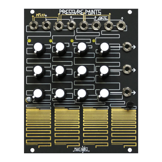
Pressure Points Panel Connections CHannel 1 Pressure OUTput CHannel 1 Gate OUTput CHannel 2 Pressure OUTput CHannel 2 Gate OUTput CHannel 3 Pressure OUTput CHannel 3 Gate OUTput CHannel 4 Pressure OUT/ Combined Pressure OUTput CHannel 4 Gate OUT/ Combined Gate OUTput Active Stage Indicator LEDs Tuned Voltage Out X: 0 to 8V. -
Page 9: Overview
CHAINing Pressure Points: Requires the 10 PIN CHAIN Cable, which is available where ever Pressure Points is sold, and the proper setting of jumpers on the modules to be CHAINed. Refer to the drawing on opposing page. All modules in the CHAIN will need to be connected to the power supply via their supplied power cables. -
Page 10: Tips & Tricks
Set up a VCO for two-operator FM by applying a SINE wave to its linear FM input, and patch it to the input of an Optomix. Patch Pressure Points Common Gate OUT to the Optomix Strike Input, and Gate OUT 3 to the DAMP input. Strike the “Bongo” with Touchplate 4 and “dampen”...
Need help?
Do you have a question about the Pressure Points and is the answer not in the manual?
Questions and answers