
Related Manuals for LUDLUM 2929

Summary of Contents for LUDLUM 2929
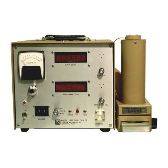
- Page 1 LUDLUM MODEL 2929 DUAL-CHANNEL SCALER January 2016 Serial Number 248597 and Succeeding Serial Numbers...
- Page 2 LUDLUM MODEL 2929 DUAL-CHANNEL SCALER January 2016 Serial Number 248597 and Succeeding Serial Numbers Shown with a Model 43-10-1...
- Page 3 RETURN OF GOODS TO MANUFACTURER If equipment needs to be returned to Ludlum Measurements, Inc. for repair or calibration, please send to the address below. All shipments should include documentation containing return shipping address, customer name, telephone number, description of service requested, and all other necessary information.
-
Page 6: Table Of Contents
Operating Procedures Calibration Procedures High Voltage Adjustment Procedures Data Output Function Identification Function Source Output Signals Removing Data from the Model 2929 Optional Equipment Model 264 Printer Model 464 RS-232 Interface Model 464-2 Two-Channel Counter Parts List Model 2929 Dual-Channel Scaler... - Page 7 Model 2929 Scaler Technical Manual Scaler Board Clock/Logic Board Dual Audio Board 6-Digit Readout Board Mother Board Preamp Board Wiring Diagram Drawings and Diagrams Ludlum Measurements, Inc. January 2016...
-
Page 8: Introduction
The Model 2929 is powered by a 95 to 250 Vac wall transformer with an output of 24 Vdc. It has a built-in detector high voltage power supply with front panel readout, as well as adjustable count time periods ranging from 0.1 to 990 minutes. -
Page 9: Specifications
Model 2929 Scaler Technical Manual Section 2 Section Specifications Power: 95 to 250 Vac wall transformer with 24 Vdc output, 50-60 Hz single phase (typically less than 100 mA) Beta-gamma lower threshold is adjustable from 4 mV, Input Senstivity: beta-gamma upper threshold is adjustable from 25 mV to 100 mV, and alpha threshold is adjustable from 175 mV. -
Page 10: Controls And Functions
Model 2929 Scaler Technical Manual Section 3 Section Controls and Functions Front Panel a 10-turn potentiometer control for adjusting HV from 200 High Voltage: V to 2500 V. It provides a linear adjustment of the detector voltage supply. Changing the detector voltage will cause the detector gain to change. A linear change in voltage will cause an exponential change in detector gain. -
Page 11: Rear Panel
Model 2929 Scaler Technical Manual Section 3 a rotary control used to vary the audio output of the Beta-Gamma Vol: beta-gamma channel from off to full volume. a rotary control used to vary the audio output of the alpha Alpha Vol: channel from off to full volume. -
Page 12: Safety Considerations
Pollution Degree 2 (as defined by IEC 664). Cleaning Instructions and Precautions The Model 2929 may be cleaned externally with a damp cloth, using only water as the wetting agent. Do not immerse the instrument in any liquid. Observe the following precautions when cleaning: 1. - Page 13 If the wrong power converter is used, the instrument and/or power converter could be damaged. The Model 2929 is marked with the following symbols: DIRECT CURRENT (DC) (IEC 417, No. 5032): designates an input receptacle that accommodates a power cord intended for connection to DC voltages.
-
Page 14: Recycling
“crossed-out wheelie bin.” This notifies the consumer that the product is not to be mixed with unsorted municipal waste when discarding; each material must be separated. On the Model 2929, the symbol will be placed on the rear panel. -
Page 15: Operating Procedures
Section 6 Section Operating Procedures Once the Model 2929 is calibrated for use with a specific detector, the high- voltage operating point must be determined. See HV adjustment procedures below for details on selecting the proper operating voltage. Selection should be based on the count rates being Count time: observed and the desired statistical accuracy. -
Page 16: High Voltage Adjustment Procedures
Model 2929 Scaler Technical Manual Section 6 Adjust the GAIN control located internally and to the right-hand side of the instrument for a positive pulse amplitude of 200 mV (at the AMP OUT connector). This completes the amplifier gain calibration. The optimum amplifier gain should be approximately 20. - Page 17 The following procedures describes the determination of the operating voltage for a Model 43-10-1 detector, which is commonly used with the Model 2929 dual channel scaler. Note that certain criteria must be met for the background counts, source efficiencies, and crosstalk.
- Page 18 Model 2929 Scaler Technical Manual Section 6 c. Alpha crosstalk in beta channel less than or equal to 10% d. Beta crosstalk in alpha channel is less than or equal to 1% e. Beta background is less than or equal to 80 cpm f.
-
Page 19: Data Output
Bit 1 Bit 2 Bit 3 Bit 4 Function Source All functions are from Model 2929 to accessory except: PIN 2 Printer Ready PIN 6 Count PIN 7 Hold Output Signals Output signals are CMOS with LO = GROUND and HI = VOLTAGE on Pin 8. -
Page 20: Removing Data From The Model 2929
Pin 7 Hold: Signal should be pulled low to stop counting. Removing Data from the Model 2929 When the Model 2929 has timed out and counting stops, a HI pulse appears on pin 1 (count complete). This pulse is approximately 2 milliseconds wide and is used to signal the accessory unit that data is ready to be transmitted. - Page 21 The suggested circuit for this is shown in Figure 2. Pins 9 and 10 are +5 V pulses and are present even if the Model 2929 is not in a count cycle. Figure 2 Ludlum Measurements, Inc. Page 7-3...
-
Page 22: Optional Equipment
ON. Model 464 RS-232 Interface The LMI Model 464 RS-232 interface connects to the Model 2929, allowing communication between the scaler and a device with an RS- 232c I/O (Input/Output), such as a personal computer (PC). -
Page 23: Model 464-2 Two-Channel Counter
NOTE: The Model 464-2 accumulates counts independently from the Model 2929 and its internal timer. Pulses are sent to the Model 464-2 counters, regardless of the status of the Model 2929 control board. This allows the user to take timed counts at the Model 2929 without affecting the serial port operation. -
Page 24: Parts List
Model 2929 Scaler Technical Manual Section 9 Section Parts List Reference Description Part Number Model 2929 Dual- UNIT Completely Assembled Channel Scaler Model 2929 48-1426 Power Supply Board, BOARD Assembled Power Supply Drawing 337 x 27 5337-031 CAPACITORS 100pF, 3kV 04-5532 2.2µF, 20V, DT... - Page 25 Model 2929 Scaler Technical Manual Section 9 Reference Description Part Number DIODE 1N4148 07-6272 CR2-CR5 GI250-2 07-6266 THERM-RL 1006 07-6322 THERM-RL 1006 07-6322 RESISTORS 220K, 1/4W, 5% 10-7066 R2-R3 1G, FHV-1, 2% 12-7686 1M, 1/4W, 5% 10-7028 301 OHM, 1/8W, 1%...
- Page 26 Model 2929 Scaler Technical Manual Section 9 Reference Description Part Number 2N3904 05-5755 TRANSISTORS INTEGRATED U1-U2 CA3096 06-6023 CIRCUITS U3-U4 CA3290 06-6140 U5-U7 CD4098 06-6066 DIODE 1N4148 07-6272 VOLTAGE REGULATORS LM78L05 05-5815 R1-R4 10K TRIMMER 09-6794 200K TRIMMER 09-6791 50K TRIMMER...
-
Page 27: Scaler Board
Model 2929 Scaler Technical Manual Section 9 330 OHMS, 1/4W, 5% 10-7053 1K, 1/4W, 5% 10-7009 22K, 1/4W, 1% 10-7070 R74-R75 56K, 1/4W, 5% 10-7021 10K, 1/4W, 5% 10-7016 330 OHMS, 1/4W, 5% 10-7053 Scaler Board, BOARD Completely Assembled Scaler... -
Page 28: Clock/Logic Board
Model 2929 Scaler Technical Manual Section 9 Reference Description Part Number Clock/Logic Board, BOARD Completely Assembled Drawing 167 x 363 Clock/Logic 5167-362 CRYSTAL Micro Xtal X0-43B-1.0 01-5356 CAPACITORS 0.01µF, 100V 04-5523 TRANSISTORS 2N3904 05-5755 INTEGRATED CIRCUITS CD4093 06-6030 CD4001 06-6064... -
Page 29: Dual Audio Board
Model 2929 Scaler Technical Manual Section 9 Dual Audio Board, Reference Description Part Number Drawing 337 x 58 BOARD Assembled Dual Audio 5337-066 C2-C5 0.01µF 04-5523 CAPACITORS 100µF, 10V, DT 04-5576 TRANSISTORS Q1-Q2 VN2222LL 05-5816 INTEGRATED CIRCUITS U1-U2 ICM7555IPA 06-6136... -
Page 30: Preamp Board
Model 2929 Scaler Technical Manual Section 9 Reference Description Part Number RESISTORS 560 OHM, 1/4W, 5% 10-7054 10K, 1/4W, 1% 12-7540 560 OHM, 1/4W, 5% 10-7054 DIODES 1N5819 07-6306 1N4001 07-6268 VOLTAGE REGULATORS LM2597-5.0 06-6723 LM78L12ACZ 05-5812 CJ50-20A-30 13-8050 CONNECTORS... -
Page 31: Wiring Diagram
Model 2929 Scaler Technical Manual Section 9 Reference Description Part Number RESISTORS 22K, 1/4W, 5% 10-7070 22K, 1/4W, 5% 10-7070 10K, 1/4W, 5% 10-7016 33K, 1/4W, 5% 10-7019 330 OHMS, 1/4W, 5% 10-7053 10K, 1/4W, 5% 10-7016 1K, 1/4W, 5%... - Page 32 Model 2929 Scaler Pulser Technical Manual Section 9 Reference Description Part Number 10K, 10-TURN 09-6761 RESISTORS 1 MEG, 1/4W, 5% 10-7028 10K TRIMMER 09-6753 10K, 1/4W, 5% 10-7016 10K TRIMMER 09-6753 2.2K, 1/4W, 5% 10-7012 TRANSFORMER M2929 X5 4275-023 VOLTAGE...
-
Page 33: Amplifier/Discriminator Board
Model 2929 Scaler Technical Manual Section 10 Section Drawings Power Supply Board, Drawing 337 x 27 Power Supply Board Component Layout, Drawing 377 x 35 Amplifier/Discriminator Board, Drawing 337x 19 Amplifier/Discriminator Board Component Layout, 337 x 4-42A Scaler/Ratemeter Board, Drawing 167 x 170...
Need help?
Do you have a question about the 2929 and is the answer not in the manual?
Questions and answers