Sign In
Upload
Download
Table of Contents
Contents
Add to my manuals
Delete from my manuals
Share
URL of this page:
HTML Link:
Bookmark this page
Add
Manual will be automatically added to "My Manuals"
Print this page
×
Bookmark added
×
Added to my manuals
Manuals
Brands
HBM Manuals
Control Systems
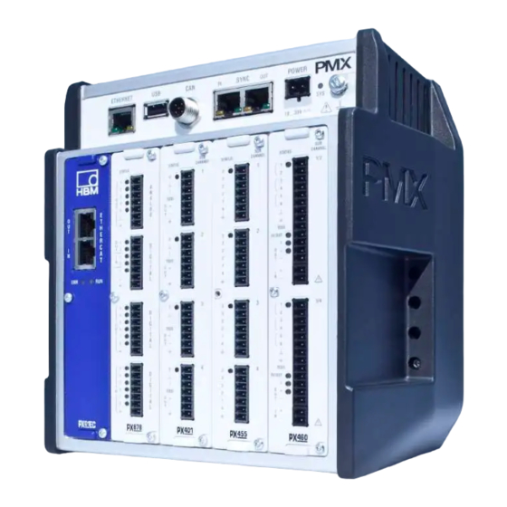
PX455
Operating manual
HBM PX455 Operating Manual
Px series
Hide thumbs
1
2
Table Of Contents
3
4
5
6
7
8
9
10
11
12
13
14
15
16
17
18
19
20
21
22
23
24
25
26
27
28
29
30
31
32
33
34
35
36
37
38
39
40
41
42
43
44
45
46
47
48
49
50
51
52
53
54
55
56
57
58
59
60
61
62
63
64
65
66
67
68
69
70
71
72
73
74
75
76
77
78
79
80
81
82
83
84
85
86
87
88
89
90
91
92
93
94
95
96
97
98
99
100
101
102
103
104
105
106
107
108
109
110
111
112
113
114
115
116
117
118
119
120
121
122
123
124
125
126
127
128
129
130
131
132
133
134
135
136
137
138
139
140
141
142
143
144
145
146
147
148
149
150
151
152
153
154
155
156
157
158
159
160
161
162
163
164
165
166
167
168
169
170
171
172
173
174
175
176
177
178
179
180
181
182
183
184
185
186
187
188
189
190
191
192
193
194
195
196
197
198
199
200
201
202
203
204
205
206
207
208
209
210
211
212
213
214
215
216
217
218
219
220
221
222
223
224
225
226
227
228
229
230
231
232
233
234
235
236
237
238
239
240
241
242
243
244
245
246
247
248
249
250
251
252
253
254
255
256
257
258
259
260
261
262
263
264
265
266
267
268
269
270
271
272
273
274
275
276
277
278
279
280
281
282
283
284
285
286
287
288
289
290
291
292
293
294
295
296
297
298
299
300
301
302
303
304
305
306
307
308
309
310
311
312
313
314
315
316
317
318
319
320
321
322
323
324
325
326
327
328
329
330
331
332
333
334
335
336
337
338
339
340
341
342
343
344
345
346
347
348
349
350
351
352
353
354
355
356
357
358
359
360
361
362
363
364
365
366
367
368
369
370
371
372
373
374
375
376
377
378
379
380
381
382
383
384
385
386
387
388
389
390
391
392
393
394
395
396
397
398
399
400
401
402
403
404
405
406
407
408
409
410
411
412
413
414
415
416
417
418
419
420
421
422
423
424
425
426
427
428
429
430
431
432
433
434
435
436
437
438
439
440
441
442
443
444
445
446
447
448
449
450
451
452
453
454
455
456
457
458
459
460
461
462
463
464
465
466
467
468
469
470
471
472
473
474
475
476
477
478
479
480
481
482
483
484
485
486
487
488
489
490
491
492
493
494
495
496
497
498
499
500
501
502
503
504
505
506
507
508
509
510
511
512
513
514
515
516
517
518
519
520
521
522
523
524
525
526
527
528
529
530
531
532
533
534
535
536
537
538
539
540
541
542
543
544
545
546
547
548
549
550
551
552
page
of
552
Go
/
552
Contents
Table of Contents
Bookmarks
Table of Contents
Table of Contents
Safety Instructions
Symbols on the Device
User Information
Using this Manual
About the PMX Documentation
Symbols Used in this Manual
PMX Product Description
Model Overview, Scope of Supply, Accessories
The PMX System
Accessories
Scope of Delivery
PMX Web Server/Software
Degree of Protection / Housing / Shielding Design
Mounting Tools and Tightening Torques
Mounting/Dismounting/Replacing
Support Rail Mounting
Wall-Mounting
Replacing Measurement and Communication Cards
Electrical Connections PMX
Plug Technology and Clamping Areas
Overview of PMX Functions
Combination Options
Relevance of the Basic Device Connection Sockets
Leds for System Monitoring (Device LED)
Fieldbus LED
Measurement Card Leds
Supply Voltage
Measurement Cards / Transducer Connection
Intrinsically Safe Measurement Circuits - Operation with Zener Barriers
Px455
Strain Gage and Inductive Full and Half Bridges
(6-Wire Configuration)
Strain Gage and Inductive Full and Half Bridges
(4-Wire Configuration)
Lvdt
Potentiometric Transducer
PX455 with Pt100 Temperature Measurement
Px401
Voltage Source ± 10 V
Current Source ± 20 Ma
Current Source ± 20 Ma
IEPE Transducers with External Measuring Amplifier
PX401 with Charge Amplifier
Px460
Voltage Supply for Signal Transmitter and Transducer up to 24 VDC Nominal (Rated) Voltage
Voltage Supply for Signal Transmitter and Transducer up to 5 VDC Nominal (Rated) Voltage
Frequency Measurement Symmetrical (Differential)
Frequency Measurement Symmetrical (Single-Pole)
Encoder and Incremental Encoder, Symmetrical (Differential)
Encoder and Incremental Encoder, Asymmetrical (Single-Pole)
SSI Encoder (Active Only)
Inductive Encoder or Pulse Encoder (Passive Only)
Connection and Configuration of the HBM Torque Flange (T10, T12, T40)
Connection and Configuration of the HBM Torque Transducer T20WN (Without VK20A)
Connection and Configuration of the HBM Torque Transducer T20WN (with VK20A)
Input/Output Cards
Analog Output ± 10 V
Px878
Digital Inputs / Digital Outputs
External Supply Voltage for Digital Inputs and Outputs (PX878)
Communication Cards
Pin Assignment PX01EC Ethercat® Fieldbus Module
Pin Assignment PX01EP Ethernet/Ip Fieldbus Module
Pin Assignment PX01PN PROFINET-IO Fieldbus Module
TEDS Transducer
TEDS Connection
PMX Parameterization with TEDS
Synchronization and Time Recording
Synchronizing Via Internal PMX Synchronization
External Synchronous Measurement Acquisition Via an NTP Server in the Network
Measurement Acquisition Via Ethercat Fieldbus, Profinet, Ethernet/Ip
Comparison of Synchronization Mechanisms
Network, Data Security, Policies, Passwords
Network Access and Remote Maintenance
Data Security
Policies Definition and Passwords
Starting up the TEDS Module
Policies Definition
Passwords
Startup
Hardware Setup
Ethernet Connection
Integrated PMX Web Server
Voltage Supply / Transducers
System Requirements
Connect the PMX with a PC (HOST) or Via a Network
Restoring Lost Network Settings
Display and Control Options
Menu Structure PMX Web Server
Overview -> SETTINGS
Factory Settings
PMX Startup Behavior
PMX Operating Behavior
Signal Runtimes
Fieldbus Integration
PROFINET Connection
Ethercat® Connection
Adjusting the Fieldbus Update Rate
Ethernet/Ip Connection
Quick Start
Preparing the Measurement System
Typical Operating Procedure
Measurement Example
Update Software (PMX Web Server)
Internal Calculation Channels
Calculation Rate
Description of Calculations
Characteristic Curve Table (21 Interpolation Points)
Scaling
Two-Point Scaling
Polynomial 4Th Order
Taring
6X6 Matrix
SG Stress Analysis
Evaluation Functions
Filter (High Pass, Low Pass, CAMSA)
Angular Synchronous Filter
Extreme Value (Peak)
Tolerance Window
Hold Function (Analog)
Hold (Digital)
Mean Values (Arithmetic, RMS)
Moving Average
Trigger Function (Range)
10Trigger Function (Pulse)
Adder
Mathematical Functions
Multiplier
Counter
Divider
Integrator
Differentiator
Cartesian to Polar Coordinates
Polar Coordinates to Cartesian Coordinates
10Constant Signal
Modulo Function
2-State Controller
Technology Functions
PID Controller
RTD PT100 at PX455
Signal Generators (Rectangle, Triangle, Sine)
Logic Modules (AND, or
Dead Time
Multiplexer 4:1
Edge Detector
Pulse Width Measurement
Timer
Connection with (Optional) Delay (CODESYS)
Example Calculations
Generation of Peak Values
Calculating the Force Introduction Point
Mechanical Work Via Force/Displacement Integration
Testing Force at Specific Points on the Displacement Axis
Force/Displacement Measurement with Relative Zero Point
Checking Force against a Tolerance Band
Event Counter
Test Signals and Signal Generators
Parameter Sets (Measurement Programs)
Setting Parameter Sets
Changing from Parameters to Parameter Sets
Communication with a Control System
Device Description File
Data Transmission by Fieldbus
Setting the Transmission Speed of the Fieldbus
Device Data (Cyclic)
Input Data, PMX Acontroller (PLC)
System Status
Measured Values (Cyclic)
Measured Value Status
Device Data (Cyclic)
Output Data, Controller (PLC) a PMX
Measured Value Control Words (Cyclic)
Measured Value Control Words
Fieldbus Channels
Profinet
Ethercat
Using the PMX Coe Object Dictionary
Configuration
Ethernet/Ip
Channel Settings
Data Structure
CAN Interface (WGX001 Only)
CAN Pin Assignment
General
Canopen Master / Slave Operation
CODESYS-V3 Soft PLC (WGX001 Only)
General
Preparation
Create Project
Add PMX Library
PMX Library
Task Configuration
Cyclic Data
Signal Run Diagram (I/O-Mapping)
All
System Events for PMX
Com.hbm.fwconfig
Com.hbm.parameter
Com.hbm.fpgasrv
Com.hbm.syscfgmgr
Com.hbm.storagemanager
Com.hbm.sigproc
Com.hbm.fieldbus
Com.hbm.meassrv
Webvisualisation
CAN Interface
Can‐Master and Slave Mode
PMX Package
Data Storage
Data Acquisition Software (DAQ) Catmaneasy/Ap
PMX Command Set (API)
Example: TELNET Connection
Command List
Examples
Object Directory
Measuring Channels
Calculated Channels
General Objects
Measuring Channels
The Constant Signals
Data Types
Access Via Ethernet Command Interface
Access Via Field Bus
Submitting a Request
Bit Allocation
The Reply from PMX
Reply to a Read Request
Make the New Value Effective
Value Ranges of the Objects
Firmware Update
Install Firmware
Diagnosis and Maintenance
Error Messages of the Device Status
Error in Factory Settings
Buffer Overflow in Command Interface
Resetting the PMX Administrator Password
Resetting the PMX to Factory Settings
Restoring Lost PMX Network Settings and Device Names
Replacing Measurement and Communication Cards
Log File
System Log Entries for System Status
System Log Entries for Channel Status / Measured Value Status
Quality Certification and Calibration Certificates
Technical Support
Waste Disposal and Environmental Protection
Glossary
Index
Advertisement
Quick Links
1
Electrical Connections Pmx
2
Px455
Download this manual
Operating Manual
English
PMX
Table of
Contents
Previous
Page
Next
Page
1
2
3
4
5
Advertisement
Table of Contents
Need help?
Do you have a question about the PX455 and is the answer not in the manual?
Ask a question
Questions and answers
Subscribe to Our Youtube Channel
Related Manuals for HBM PX455
Control Systems HBM PX460 Operating Manual
Px series (552 pages)
Control Systems HBM PX878 Operating Manual
Px series (552 pages)
This manual is also suitable for:
Px401
Px460
Px878
Table of Contents
Print
Rename the bookmark
Delete bookmark?
Delete from my manuals?
Login
Sign In
OR
Sign in with Facebook
Sign in with Google
Upload manual
Upload from disk
Upload from URL


Need help?
Do you have a question about the PX455 and is the answer not in the manual?
Questions and answers