Table of Contents
Advertisement
Advertisement
Table of Contents

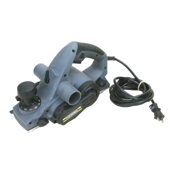
Summary of Contents for Performax 241-0993
- Page 1 Planer 241-0993 OPERATOR’S MANUAL CAUTION: To Reduce The Risk Of Injury, User Must Read And Understand Operator’s Manual. Save These Instructions For Future Reference. For questions / comments, technical assistance or repair parts – Please Call Toll Free: 1-866-858-2664. (M-F 8:30am-5:00pm Est.)
-
Page 2: Table Of Contents
TABLE OF CONTENTS Safety Symbols ............Page 2 Safety Instructions . -
Page 3: Safety Symbols
SAFETY SYMBOLS Some of these following symbols may be used on this tool. Please study them and learn their meaning. Proper interpretation of these symbols will allow you to operate the tool better and more safely. Symbol Designation / Explanation Name Volts Voltage... -
Page 4: Safety Instructions
SAFETY INSTRUCTIONS The purpose of safety symbols is to attract your attention to possible dangers. The safety symbols, and the explanations with them, deserve your careful attention and understanding. The symbol warnings do not, by themselves, eliminate any danger. The instructions and warnings they give are no substitutes for proper accident prevention measures. -
Page 5: Safety Warnings
SAFETY INSTRUCTIONS GERNERAL POWER TOOL Do not abuse the cord. Never use the cord for carrying, pulling or unplugging the SAFETY WARNINGS power tool. Keep cord away from heat, oil, sharp edges or moving parts. Damaged or WARNING: Read all safety entangled cords increase the risk of electric warnings and all instructions. - Page 6 SAFETY INSTRUCTIONS 6. Dress properly. Do not wear loose 7. Use the power tool, accessories, clothing or jewelry. Keep your hair, clothing tool bits, etc. in accordance with these and gloves away from moving parts. Loose instructions, taking into account the working conditions and the work to be clothes, jewelry or long hair can be caught in performed.
- Page 7 SAFETY INSTRUCTIONS 2. Check the workpiece for nails. If there Your risk from these exposures varies, are nails, either remove them or set them depending on how often you do this type well below the intended finished surface. of work. To reduce your exposure to these If the planer blades strike objects like nails chemical: work in a well ventilated area, they may cause the tool to kickback, and...
- Page 8 OVERVIEW Lock-off button ON/OFF Trigger switch Handle Rabbeting depth stop Dust/chip extraction guide switch Depth-adjustment knob Fixed rear base Wrench storage Adjustable front base sleeve Dust/chip extraction Edge-guide port (x 2) attachment knob Dust bag Blade Clamping element Edge guide Clamping screw SPECIFICATIONS Motor...
-
Page 9: Assembly
ASSEMBLY REPLACING THE PLANER WARNING: If any part is broken BLADES or missing, DO NOT attempt to plug in the power cord or operate the tool until the CAUTION: broken or missing part is replaced. Failure Always ensure that to do so could result in possible serious the tool is switched OFF and unplugged injury. - Page 10 ASSEMBLY INSTALLING A PLANER BLADE poor planing action and tool breakdown. Tighten the clamping screws carefully (FIG. 3) when attaching the blades to the planer. A loose clamping screw could be extremely 1. Disconnect the plug from power source. dangerous. Regularly check and ensure 2.
- Page 11 ASSEMBLY ADJUSTING THE RABBETING proper cutting depth should determined according to the hardness, DEPTH STOP (FIG. 6) gumminess or moisture content of the material being cut, as well as the feed rate, The rabbeting depth stop allows the user and is largely a matter of experience. Rotate to set any rabbeting depth from 0 to 23/32”...
- Page 12 ASSEMBLY DUST BAG (FIG. 9-10) BLADE CHANGE WRENCH STORAGE AREA (FIG. 11) • The planer is equipped with two dust/ chip extraction ports, either which may Your tool is equipped with a blade wrench be used with a dust bag to keep your that is conveniently located in the handle work environment cleaner.
-
Page 13: Operation
OPERATION SWITCHING ON AND OFF 6. Switch on the tool, allow it to reach full speed, and guide the tool with even (FIG. 13) feed over the surface to be planed. 7. Move the tool gently forward, applying CAUTION: Before plugging the pressure on the front of the tool at machine into the power supply, always the beginning of the planing pass and... - Page 14 OPERATION PLANING WITH THE EDGE GUIDE CHAMFERING (FIG. 16) (FIG. 15) The “V” groove in the front base allows quick and easy chamfering of workpiece edges. The edge guide can be used to control the 1. Place the “V” groove on the front base width of the cut or for simply providing over the edge to be chamfered.
-
Page 15: Maintenance
MAINTENANCE BEFORE EACH USE WARNING: Do not let brake fluids, gasoline, petroleum-based products, 1. Inspect the planer, the trigger switch, the penetrating oil, etc., come into contact cord and the accessories for damage. with plastic parts. They contain chemicals 2. Check for damaged, missing, or worn that can damage, weaken, or destroy parts. - Page 16 NOTES Page 15...
- Page 17 NOTES Page 16...
- Page 18 NOTES Page 17...
-
Page 19: Warranty
This PERFORMAX brand power tool carries our 30-Day Money Back Guarantee. ® If you are not completely satisfied with your PERFORMAX brand power tool ® for any reason within thirty (30) days from the date of purchase, return the tool... - Page 20 © 2016 Menard, Inc., Eau Claire, WI 54703 04/2016...
Need help?
Do you have a question about the 241-0993 and is the answer not in the manual?
Questions and answers