
Related Manuals for Monosem DM-4600

Summary of Contents for Monosem DM-4600
- Page 1 TABLE OF CONTENTS OPERATOR’S MANUAL DM-4600 Monosem, Inc. 1001 Blake St. Edwardsville, KS 66111 (913) 438-1700 www.monosem-inc.com...
- Page 2 OPERATOR’S MANUAL NOTES: DM-4600...
-
Page 3: Table Of Contents
Lift Switch Configuration / Hopper Type Sensor Setup ............21 VAC/Pressure Sensor Setup ....................22-23 Flow meter installation ......................24-27 Master Flow Sensor........................28 Post Season Storage ....................... 29 Harness Pinouts ........................30-32 Parts and Accessories ......................33-34 Warranty ............................36 DM-4600... -
Page 4: System Overview
INTRODUCTION System Overview The DM-4600 Planter Monitor is designed for maximum performance in the field and is easy to install and use. The system is capable of monitoring up to 32 rows and provides not only seed population, but also will display area, and has capabilities of monitoring liquid flow with Monosem “Visu-Flo Technology”. -
Page 5: Specifications
24.1 cm W x 18 cm H x 6.8 cm D (9.5" W x 7" H x 2.7" D) Weight 3.58 kg (7.9 lb) for 32-row DM-4600 system Wire Harnesses The DM-4600 includes detachable harnesses to supply the unit's power (fused) and sensor inputs (to hitch). -
Page 6: Installation
OPERATOR’S MANUAL INSTALLATION Your DM-4600 comes with a RAM 1 ½” Mounting Ball. Any RAM Mount 1 ½” fixtures will adapt to your monitor. Optional RAM Base Mount Part Number: 301108 Install the RAM-238-U 1 ½” Ball supplied with your console by removing the two screws from the rear of the unit and use them to attach the ball. - Page 7 The 301106 harness will attach to your planter with a 37 pin AMP CPC style connector. This connector is pinned to match standards used by Monosem. If you are using an external speed source such as a radar or external GPS, connect it to the 4 pin AMP connector on the back of the monitor.
-
Page 8: Quick Start
After the desired configuration is set, touch “OK” in top right of pop up screen. (Ref Master flow meter set up on pg. 28) DM-4600... - Page 9 Screen at right shows a 12 row seed monitor with 12 flow meters and two different flow rates. The funnel is for flow blockage sensors often used on air seeders. DM-4600...
-
Page 10: Target Rates
(found on your flowmeters) and then enter the desired GPA along with the limits. The calibration number is auto generated. If you have two flow inputs, you will scroll to flow 2 setup where you will repeat the above steps. DM-4600... -
Page 11: Sensor Setup
Day/Night Mode are set. Conversion units may be set to English or Metric. Show IO Numbers when enabled will show the actual input pin number on the bar graph row indicators. This is normally set to No. DM-4600... -
Page 12: Speed Setup
This is done by driving a 400 foot course. It is suggested that you do 4 runs and the monitor will store and average them for you. Flag your course and as you pass the first flag, press Start. DM-4600... - Page 13 Acres. This count can be check box at the bottom, Started or Stopped with the Enable/Disable buttons. You the check box text is “No may also reset the Acre count at any time. Sensors”. DM-4600...
-
Page 14: Monitor Operations
The first selection gives the option of selecting a row and parking on it. The second shows Min-Max-Avg for the product and the last shows a 20 second moving line graph history of a selected row. DM-4600... - Page 15 It may be returned to normal operation by holding the row down again. THE DASH SCREEN - SEEDS The Seeds Dash Screen gives a quick overview of the operation. Shown at left is Population in Seeds/Acre with the Average, the Minimum (Row Number) and Maximum (Row Number). DM-4600...
-
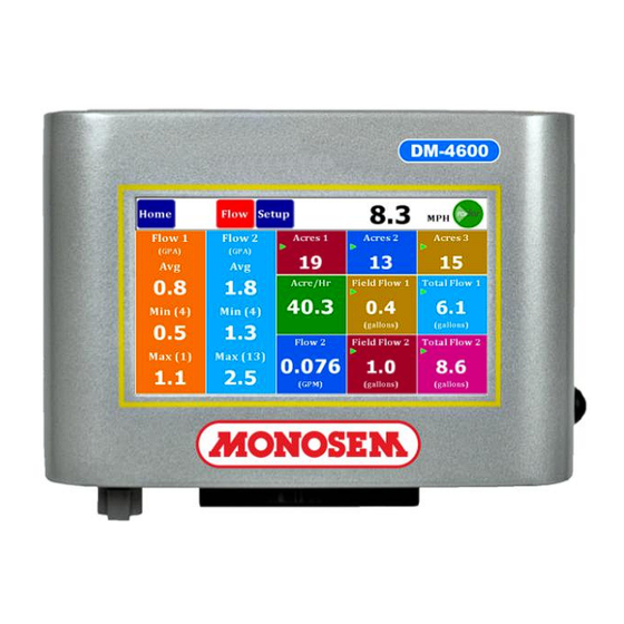
Page 16: Dash View
With the VAC and Pressure capabilities, Tiles are available on the Seed and Flow Dashboards. Tile Assignments will be saved for future power up cycles. All configurable Tiles in the Dash boards are now identified with a small peel flip icon in the lower right corner of the Tile. DM-4600... - Page 17 Total Flow 2 which may be started/stopped or cleared by holding the button down for three seconds. The center lower 2 tiles can be configured with existing Acres/Hr, Flow GPM and the new Pressure or Vac sensor values. Simply press on the Tiles and a dialog box will appear with possible Tile Assignments. DM-4600...
-
Page 18: Singulation Screen
For each row graphical object you can see the present Skips and Multiple percentages. Skips are shown in yellow above the center line and Multiples are shown in Red below the center line. If neither of these colors show for a given Row this would indicate 100 % singulation. DM-4600... -
Page 19: Mph Indicator
The final screen is manual speed where enter speed incrementing with the gold boxes. To toggle from one input to another, INTERNAL GPS STATUS hold down the icon for 2-3 seconds and a dialog box will appear. DM-4600... -
Page 20: Internal Gps Status
This upper right corner area is described more fully in the MPH INDICATOR section of the DM-4600 Operators Manual on page 15. The GPS ICON indicates the Signal Strength and GPS Lock Status. The ICON is made up of 5 bars, the left 4 bars indicate the Signal Strength and the tall bar on the far right indicates the GPS Lock Status. -
Page 21: Lift Switch Configuration / Hopper Type Sensor Setup
The Lift switch may now be configured to be Normally Open or Normally Closed to accommodate diff rent lift switches HOPPER TYPE SENSOR SETUP Hopper Type to Setup/Implement/Sensor/Hopper screen, allowing user to select Active Low or Active High Hopper Sensors. DM-4600... -
Page 22: Vac/Pressure Sensor Setup
To select the desired Sensor type Press on the Sensor Selection button. This button will provide a selection dialog box as follows. The list includes Off, Raven – Pressure, Dickey John – Pressure, Dickey John – Vacuum and John Deere – Vacuum. DM-4600... - Page 23 The Raven- Pressure Sensor requires a calibration. You may press the “Calibrate” purple button to calibration your sensor. When you do this the following screen will provide you with more steps. If you Press the “Calibrate Now” button the system will show the following screen while it performs the Calibrate function. DM-4600...
-
Page 24: Flow Meter Installation
The lines will stay filled with liquid and leakage on the ends will be prevented when the unit is raised. Properly sized orifice plates will make the application rate accurate and consistent from row to row. DM-4600... - Page 25 It is made into the housing on the opposite side of where the cable goes into the meter. It is very critical that the flow meters are installed following this direction of flow indicator. Inaccurate or inconsistent readings will occur if they are installed backward. DM-4600...
-
Page 26: Flow Direction
This will also make the wiring harness less complex as the length of wire required to hook the flow meters up will not be very long and all the connections will be in one location close to this grouping. DM-4600... - Page 27 Once again if you have made plans for flushing of the system and planting is delayed we would recommend, you go ahead and flush the system to insure no problems will occur on startup. DM-4600...
-
Page 28: Master Flow Sensor
To accommodate configuring of the Master Flow sensor a Implement Configuration screen was developed. In this screen you can select Flow type for each flow setup. The flow type would be the normal Per Row of the Master Flow sensor. DM-4600... -
Page 29: Post Season Storage
10 gallon, resulting in the calibration number needing converted Ex: 710/10 = 71 pulses per gallon. Post Season Storage for the Monosem Visu-Flo Flow Meters Within 2 to 3 days of finishing for the season we strongly recommend a total cleansing of the system with water. -
Page 30: Harness Pinouts
((red/black/green) E3 - F1 No Connection 8 V Sensor Power (red) 8 V Sensor Power (black) 4 Pin Console pinout DM-4600 Power In/ Alarm Out Pin # Description 12 VDC IN (red) -12VDC IN (black) Visual Alarm Out (rd/wh) Visual Alarm Return (bk/wh) - Page 31 TABLE OF CONTENTS 30 Pin Console Pinout 37 Pin Implement Harness Connector DM-4600 Console Connector DM-4600 Implement Harness Pin # Description Pin # Description Row 1 (green) Row 1 (green) Row 2 (white) Row 2 (white) Row 3 (brown) Row 3 (brown)
- Page 32 TABLE OF CONTENTS 10 Pin Accessory Harness Pinout DM-4600 Accessory Harness Pin # Description Hopper Level 1 (green) Hopper Level 2 (white) RPM 1 (brown) RPM 2 (blue) VAC 1 frequency input (orange) VAC 2 frequency input (yellow) VAC 1 analog input (purple)
-
Page 33: Parts And Accessories
OPERATOR’S MANUAL PARTS INFORMATION Monitor Description Part Number DM-4600 Console Only 301103 RAM Ball Mount 301107 RAM Arm and Base Kit 301108 (Optional) Visual Alarm (Optional) 301109 Many other harness options are available. Console Harnesses Description Part Number Console Power Harness 12’... - Page 34 Visu-Flo Harness to Dj 237-16Y Seed Harness Visu-Flo Harness to 237-8VJ Deere Seed Harness 237- Visu-Flo Harness to 12VJ Deere Seed Harness 237- Visu-Flo Harness to 16VJ Deere Seed Harness Hitch extensions are available; see our catalog for lengths and prices. DM-4600...
- Page 35 OPERATOR’S MANUAL NOTES: DM-4600...
-
Page 36: Warranty
OPERATOR’S MANUAL Monosem, Inc. 1001 Blake St. Edwardsville, KS 66111 Ph. (913) 438-1700 www.monosem-inc.com Rev 0217 DM-4600...
Need help?
Do you have a question about the DM-4600 and is the answer not in the manual?
Questions and answers