Table of Contents

Summary of Contents for Teleflex CH2100P
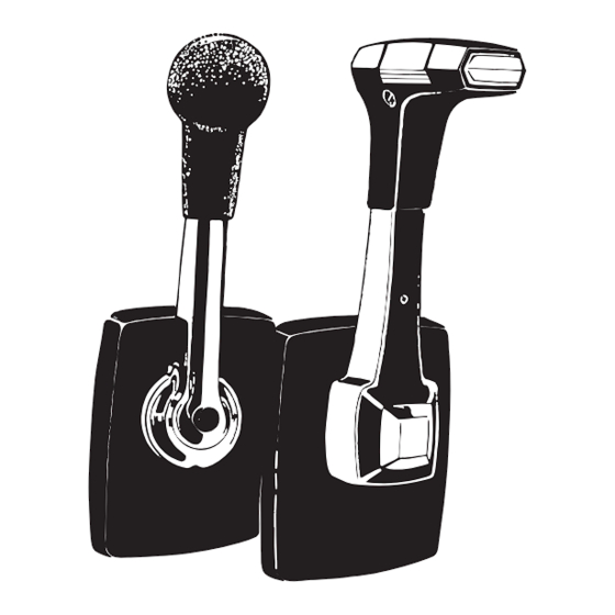
- Page 1 marine engine controls for side mounting Installer These instructions contain important safety information and must be forwarded to the boat owner. This pdf was downloaded from MarineSupplyDock.com...
- Page 2 Preparations NB! Before starting the installation please read the instruction carefully When deciding on the best position for the control keep the control lever movements in mind. Ensure full throttle movement without obstruction at position chosen before the hole is cut. Also check that space required for installation is sufficient.
- Page 3 Using the mechanism Cable travel must be in accordance with the engine. Standard feature of the mechanism is pulling throttle function. This can be changed to pushing throttle function: • Remove screw and washer (J&K fig. 2). Lift off the throttle lever (H fig.
- Page 4 Installing the control Mark the cut out area using the templates (enclosed page). Make sure the control is placed in the correct position. Cut the hole and drill the holes for the attachment screws using a 4,0 mm drill. Connecting the cables Check that the lever movements are correct.
- Page 5 Installation of cables The minimum control cable bend radius is 200 mm. Sharper bends will increase cable wear rapidly. Throttle cable As the throttle cable moves back and forth during opera- tion, it must not be clamped too close to the mechanism as this would prevent its motion.
- Page 6 • Secure the mechanism with the 4 selftapping screws supplied (Fig. 16) and remove the lever. Controls without attachment plate: • Fit the cover. Make sure the tabs snap properly into lugs (B fig. 16). Controls with attachment plate: • Push the 2 cover halves sideways to meet at the lever shaft.
- Page 7 Accessories Neutral safety switch •The engine control can be equipped with a neutral safety switch to prevent accidental starting with gear engaged. NB The switch (A fig. 20) must be mounted with the electrical plugs (B fig. 20) turned away from the gear cable.
- Page 8 Distributor 640 North Lewis Road Limerick, PA 19468 USA 610-495-7011 www.teleflexmarine.com This pdf was downloaded from MarineSupplyDock.com...
- Page 9 Sidomonterade motorreglage för marinmotorer Till installatören Denna instruktion innehåller viktig säkerhets- information och måste medfölja båten This pdf was downloaded from MarineSupplyDock.com...
- Page 10 Förberedelser OBS! Var vänlig läs hela installations- anvisningen före montering påbörjas. När bästa placering för reglaget skall avgöras, måste reglagespakens rörelser tagas med i beräkningen. Man måste försäkra sig om att fullt spakutslag är möjligt före hålet sågas upp. Kontrollera också att det finns tillräckligt med plats för installationen.
- Page 11 Att använda mekanismen Kabelns rörelse måste vara i enlighet med motorns krav. Mekanismens standardutförande är dragande gas. Gasfunktionen kan ändras till tryckande gas enligt följande: • Tag bort skruv och bricka (J&K fig. 2). Tag bort gasarmen (H fig. 2). •...
- Page 12 Installera reglaget Använd borrmallen och märk ut hålen. Se till att reg- laget kommer i rätt position. Såga upp hålet för reg- laget och borra skruvhålen (använd 4,0 mm borr). Kabelanslutning Kontrollera att spakrörelserna är korrekta. OBS! Anslut kablarna till mekanismen, men inte till motorn eller backslaget förrän hela in- stallationen är klar.
- Page 13 Dragning av reglagekablar Minsta krökningsradie för kabeln är 200 mm. Böjs kablarna hårdare ökar kabelslitaget. Gaskabel Eftersom gaskabeln pendlar får den inte klamras fast så nära mekanismen att dess rörelse hindras. Detta skulle medföra att reglagemekanismen överbelastas med onormalt slitage och hård växling som följd.
- Page 14 Reglage med fästöron: • Montera kåpan och se till att snäppena sitter ordentligt i mekanismens fyra fästen (B fig. 16). Reglage med fästplåt: • Skjut på de två kåphalvorna så att de möts vid axeln. Kan även göras med spaken på plats. •...
- Page 15 Tillbehör Neutrallägesbrytare • Motorreglaget kan utrustas med en neutralläges- brytare för att motverka oavsiktlig start med växeln i. OBS! Brytaren (A fig. 20) måste installeras så att kontaktstiften (B fig. 20 ) är vända från växelkabeln. DS-enhet I båtar med två manöverplatser krävs att manöverplatserna är anslutna via s.k.
- Page 16 Återförsäljare: 640 North Lewis Road Limerick, PA 19468 USA 610-495-7011 www.teleflexmarine.com This pdf was downloaded from MarineSupplyDock.com...
- Page 17 This pdf was downloaded from MarineSupplyDock.com...
Need help?
Do you have a question about the CH2100P and is the answer not in the manual?
Questions and answers