Table of Contents
Advertisement
Quick Links
Advertisement
Table of Contents

Related Manuals for Jet JCP-601


Summary of Contents for Jet JCP-601
- Page 1 Stationary Air Compressor Operating Instructions and Parts Manual Model: JCP-601 427 New Sanford Road La Vergne, Tennessee 37086 Part No. M-506601 Ph: 1.800.274.6848 Edition 2 01/2017 www.jettools.com Copyright © 2016 JET IN572001AV 2/17...
- Page 2 Please read and save these instructions. Read carefully before attempting to assemble, install, operate or maintain the product described. Protect yourself and others by observing all safety information. Failure to comply with instructions could result in personal injury and/or property damage! Retain instructions for future reference.
-
Page 3: Before You Begin
BEFORE YOU BEGIN Introduction Air compressor units are intended to provide compressed air to power pneumatic tools, operate spray guns and supply air for pneumatic valves and actuators. The pumps supplied with these units have oil lubricated bearings. A small amount of oil carryover is present in the compressed air stream. Applications requiring air free of oil vapor should have the appropriate filters installed. -
Page 4: Safety Guidelines
GENERAL SAFETY INSTRUCTIONS Safety Guidelines This manual contains information that is very important to know and understand. This information is provided for SAFETY and to PREVENT EQUIPMENT PROBLEMS. To help recognize this information, observe the following symbols. Danger indicates an imminently hazardous situation which, if not avoided, WILL result in death or serious injury. -
Page 5: Breathable Air Warning
Important Safety Information (Continued) BREATHABLE AIR WARNING This compressor/pump is not equipped and should not be used “as is” to supply breathing quality air. For any application of air for human consumption, the air compressor/pump will need to be fitted with suitable in-line safety and alarm equipment. This additional equipment is necessary to properly filter and purify the air to meet minimal specifications for Grade D breathing as described in Compressed Gas Association Commodity Specification G 7.1, OSHA 29 CFR 1910. -
Page 6: Spraying Precautions
Important Safety Information (Continued) Never use plastic (PVC) pipe for compressed air. Serious injury or death could result. Never attempt to repair or modify a tank! Welding, drilling or any other modification will weaken the tank resulting in damage from rupture or explosion. Always replace worn, cracked or damaged tanks. -
Page 7: Getting To Know Your Compressor
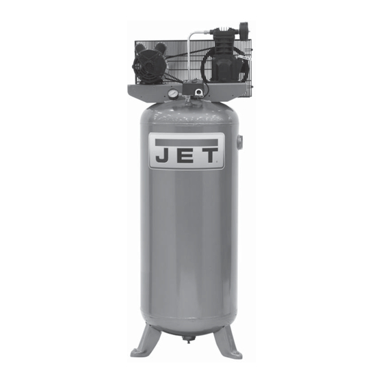
Getting To Know Your Compressor Discharge Tube Compressor Pump Air Filter Motor Pressure Switch Unloader Tube Safety Relief Valve Tank Pressure Gauge Manual Tank Drain Figure 1 - Vertical Unit Identification... -
Page 8: Specifications
SPECIFICATIONS JCP-601 Stock Number 506601 Motor HP Power 208-230V Phase Displacement CFM 12.2 Air Delivery CFM @ 90 PSI 10.2 Air Delivery CFM @ 135 PSI Max PSI Pump RPM 1020 Tank Capacity 60 gallons Unit Weight 255 lbs Amp Draw 14.5... -
Page 9: Installation Instructions
INSTALLATION INSTRUCTIONS Disconnect, tag and lock out power source then release all pressure from the system before attempting to install, service, relocate or perform any maintenance. Do not lift or move unit without appropriately rated equipment. Be sure the unit is securely attached to lifting device used. -
Page 10: Single Phase
INSTALLATION INSTRUCTIONS (CONTINUED) Installing A Shut-Off Valve A shut-off valve (not provided) should be installed on the discharge port of the tank to control the air flow out of the tank. The valve should be located between the tank and the piping system. - Page 11 INSTALLATION INSTRUCTIONS (CONTINUED) Grounding Improperly grounded electrical components are shock hazards. Make sure all the components are properly grounded to prevent death or serious injury. This product must be grounded. Grounding reduces the risk of electrical shock by providing an escape wire for the electric current if short circuit occurs.
- Page 12 INSTALLATION INSTRUCTIONS (CONTINUED) Installing Air Inlet Filter Inlet Port Screw supplied air inlet filter into inlet port of cast iron pump as indicated in Figure 6. Lubrication This unit contains no oil. Before operating compressor, fill to the center of the sight gauge (see Figure 6). Using any other type of oil may shorten pump life and damage valves.
-
Page 13: Crankcase Breather
OPERATING INSTRUCTIONS (CONTINUED) Recommended Break-In Period The compressor should be run continuously at 90 PSI or lower for one hour to allow proper seating of the piston rings. 1. Open drain cock completely and run the compressor for 60 minutes. 2. -
Page 14: Troubleshooting Guide
TROUBLESHOOTING GUIDE SYMPTOM POSSIBLE CAUSE(S) CORRECTIVE ACTION Low discharge pressure 1. Air demand exceeds pump capacity 1. Reduce air demand or use a compressor with more capacity. 2. Air leaks 2. Listen for escaping air. Apply soap solution to all fittings and connections. - Page 15 TROUBLESHOOTING GUIDE (CONTINUED) SYMPTOM POSSIBLE CAUSE(S) CORRECTIVE ACTION Reset mechanism cuts out 1. Too many devices on same circuit 1. Limit the circuit to the use of only the air compressor. repeatedly or fuses blow 2. Incorrect fuse size or circuit breaker 2.
-
Page 16: Compressor Lubrication
MAINTENANCE AND INSPECTION INSTRUCTIONS Disconnect, tag and lock out power source then release all pressure from the system before attempting to install, service, relocate or perform any maintenance. In order to maintain efficient operation of the compressor system, check the air filter and oil level before each use. -
Page 17: Operation
MAINTENANCE AND INSPECTION INSTRUCTIONS (CONTINUED) Components Turn off all power and clean the cylinder head, motor, fan blades, air lines, aftercooler and tank on a monthly basis. Belts Lock out and tag the power then release all pressure from the tank to prevent unexpected movement of the unit. - Page 18 REPAIR PARTS ILLUSTRATION FOR JCP-601 For Repair Parts, visit www.jettools.com to find your local distributor 24 hours a day – 365 days a year Please provide following information: - Model number - Serial number (if any) - Part description and number as shown in parts list...
- Page 19 REPAIR PARTS LIST FOR JCP-601 Ref. Part Ref. Part No. Description Number Qty. No. Description Number Qty. 3HP VT PUMP ASSEMBLY JCP601-001 28 BELT, AX48 VB-A48 3.2HP 240V ELECTRIC JCP601-002 29 PTFE TUBE, 1/4 IN. X 14 IN. MOTOR 30 BELT GUARD BRACKET JCP601-015 HEX HEAD SCREW, 5/16 IN.-...
- Page 20 REPAIR PARTS ILLUSTRATION FOR JCP-601 For Repair Parts, visit www.jettools.com to find your local distributor 24 hours a day – 365 days a year Please provide following information: - Model number - Serial number (if any) - Part description and number as shown in parts list...
-
Page 21: Repair Part Kits
REPAIR PARTS LIST FOR JCP-601 Ref. Description Part Number: Qty. CRANKCASE ● CRANKCASE GASKET BREATHER JCP601-021 CYLINDER ● CYLINDER GASKET CONNECTING ROD AND PISTON ASSEMBLY PISTON RING SET BALL BEARING CRANKSHAFT, BEARINGS, RODS, PISTON ASSEMBLY JCP601-022 ● O-RING OIL SEAL BEARING CAP ASSEMBLY ✝... -
Page 22: Warranty And Service
Limited Lifetime – JET Parallel clamps; VOLT Series Electric Hoists; Manual Hoists; Manual Hoist Accessories; Shop Tools; Warehouse & Dock products; Hand Tools; Air Tools NOTE: JET is a division of JPW Industries, Inc. References in this document to JET also apply to JPW Industries, Inc., or any of its successors in interest to the JET brand.
Need help?
Do you have a question about the JCP-601 and is the answer not in the manual?
Questions and answers