
Summary of Contents for Festool MS6-SV-...-D-10V24
- Page 1 Soft-start/quick exhaust valve MS6-SV-...-D-10V24 Operating instructions 8043786 1702a [8043788]...
- Page 2 Text designations: • Activities that may be carried out in any order 1. Activities that should be carried out in the order stated – General lists è Result of an action/References to more detailed information Festo – MS6-SV-...-D-10V24 – 1702a English...
-
Page 3: Table Of Contents
............Festo – MS6-SV-...-D-10V24 – 1702a English... - Page 4 ............. Festo – MS6-SV-...-D-10V24 – 1702a English...
-
Page 5: About This Document
(è 3.2 Common cause failures (CCF) and 15.1 Safety characteristics). Note Failure of the safety function Failure to observe the technical data can result in the failure of the safety function. • Observe the technical data (è 15 Technical data). Festo – MS6-SV-...-D-10V24 – 1702a English... -
Page 6: Intended Usage
MS6-SV-...-D-10V24 Intended usage The MS6-SV-...-D-10V24 hereafter called the MS6-SV-D, is an electro-pneumatic soft-start/quick exhaust valve designed in accordance with EN ISO 4414. The MS6-SV-D is intended for the following purposes: – Pressure release and pressure switch-on in higher levels in accordance with EN ISO 13849-1 –... -
Page 7: Specified Directives And Standards
Safety function in accordance with EN ISO 13849 The MS6-SV-D has features that permit achievement of a performance level e for the following safety functions: – pressure release – protection from unexpected start-up (non-switching) in accordance with EN 1037. Festo – MS6-SV-...-D-10V24 – 1702a English... -
Page 8: Requirements For Product Use
Work on safety-related systems may only be carried out by qualified personnel familiar with safety engineering. Common cause failures (CCF) To achieve the desired performance levels, the applicable measures against CCF must be implemented in accordance with the specifications of EN ISO 13849-2. Festo – MS6-SV-...-D-10V24 – 1702a English... -
Page 9: Pfhd Value
MS6-SV-...-D-10V24 value The PFH value depends on the version of the MS6-SV-D and the annual actuation rate (n value MS6-SV-…-D Actuation rate (n ) [10 Fig. 1 value MS6-SV-…-D Festo – MS6-SV-...-D-10V24 – 1702a English... -
Page 10: Range Of Applications And Certifications
Certificates and declaration of conformity for the MS6-SV-D (è www.festo.com/sp). Service Repairs may only be conducted with the parts listed in the spare parts catalogue (è www.festo.com/spareparts). Opening the housing is prohibited. Contact your regional Festo contact person if you have technical questions. Festo – MS6-SV-...-D-10V24 – 1702a English... -
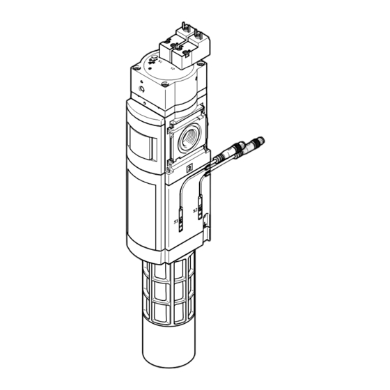
Page 11: Control Sections And Connections
Slot for proximity sensor S3 (output pressure p2) Valve body Pressure indicator (optional) Pneumatic port 1 Proximity switch S2 (operating pressure p1) Proximity switch S1 Flow control screw for soft-start function Fig. 3 Operating elements and ports Festo – MS6-SV-...-D-10V24 – 1702a English... -
Page 12: Application And Function
Port 3 (exhaust p3) Coil connection pilot valve V1 electrical Coil connection pilot valve V2 Proximity switch S1 Magnetic Proximity sensor S2 Proximity sensor S3 Flow control valve mechanical 1) Optional. Tab. 2 Interfaces Festo – MS6-SV-...-D-10V24 – 1702a English... -
Page 13: Switching Logic
Switching position 2 Full flow from port 1 to 2; passage from port 2 to 3 closed Tab. 3 Switching logic Function Symbol Function Soft-start/quick exhaust valve, electrically actuated. Tab. 4 Circuit symbol for the function Festo – MS6-SV-...-D-10V24 – 1702a English... -
Page 14: Switching Characteristics
1) After the response time the signals are applied statically. The maximum specified response times must be considered in the diagnostics. These response times are normally shorter. Tab. 5 Proximity switch response times Festo – MS6-SV-...-D-10V24 – 1702a English... -
Page 15: Switch-Through Pressure
When the output pressure p2 reaches about 50 % of the operat ing pressure p1, the maximum flow rate is enabled. Ratio of p2 to p1 [%] Filling time t Fig. 5 Switch-through pressure tolerance field Festo – MS6-SV-...-D-10V24 – 1702a English... -
Page 16: Recommendation For Activation And Diagnostics
Switch off voltage to pilot valve V2. V2 = 0 S2 = 0 è 1 Record edge change at proximity sensor S2. Corresponding response times ( è Fig. 4). Tab. 6 Recommendation for activation and diagnostics Festo – MS6-SV-...-D-10V24 – 1702a English... -
Page 17: Installation
• Observe minimum distance of 15 mm below the pneumatic silencer (è Fig. 6). The open space ensures trouble free exhausting. Information about mounting the module connector, sub-base and mounting bracket can be found in the operating instructions enclosed with the relevant accessories. Fig. 6 Installation Festo – MS6-SV-...-D-10V24 – 1702a English... - Page 18 Incorrect installation in the service combination can result in failure of the pressure release safety function. • Only devices that do not impair pressure release (also after a possible malfunction of the device) may be placed downstream of the MS6-SV-D. Festo – MS6-SV-...-D-10V24 – 1702a English...
- Page 19 MS6-WP/WPB included in the scope of delivery). 3. Place the module connectors 3 in the slots of the individual devices. 4. Fasten the module connectors with two screws. Max. 1.2 Nm Fig. 8 Assembly Festo – MS6-SV-...-D-10V24 – 1702a English...
-
Page 20: Pneumatic Installation
This can lead to complete failure of the safety function (increased residual pressure in the system after bleeding off ). • Use the safety silencer UOS-1 designed for the device (è 13 Accessories and spare parts). Festo – MS6-SV-...-D-10V24 – 1702a English... -
Page 21: Electrical Installation
The internal valves are sensed magnetically. • Make sure that there is no magnetic interference at the MS6-SV-D. • Observe enclosed operating instructions for proximity sensors. Connecting the MS6-SV-D • Connect pilot valves and proximity sensors. Festo – MS6-SV-...-D-10V24 – 1702a English... - Page 22 Emergency stop (input circuit) Digital Digital output Stop Output Feedback Feedback circuit Digital Digital input Loop Input Safety Safety switching device or safety Standard- Programmable logic controller Device Tab. 7 Designations in circuit examples Festo – MS6-SV-...-D-10V24 – 1702a English...
-
Page 23: Commissioning
1. Switch off the following energy sources to clean the outside: – operating voltage – compressed air 2. Clean the exterior of the MS6-SV-D. Soap suds (max. +50 °C), petroleum ether and all non-abrasive cleaning agents may be used. Festo – MS6-SV-...-D-10V24 – 1702a English... -
Page 24: Disassembly
Port MSC-3/2-24VDC Type C, EN 175301-803 MSC-3/2-24VDC-M12 Tab. 9 Solenoid valves Pneumatic silencer UOS-1 UOS-1-LF Tab. 10 Pneumatic silencer Accessories from the Festo catalogue (è www.festo.com/catalogue). Information about spare parts and accessories (è www.festo.com/spareparts). Festo – MS6-SV-...-D-10V24 – 1702a English... -
Page 25: Fault Clearance
• Check power supply. • Check installation of the signal lines. • Commission device (è 8 Commissioning). • Implement possible remedies (è Tab. 11). If the malfunction occurs again: • Contact Festo repair service. Festo – MS6-SV-...-D-10V24 – 1702a English... -
Page 26: Technical Data
1) The indicated value was determined using the silencer UOS-1. Depending on the level of contamination of the silencer the residual pressure can be higher. It is the task of the user/operator to determine how probable additional hazards are, and whether addition al measures are required. Festo – MS6-SV-...-D-10V24 – 1702a English... - Page 27 1) The indicated value was determined using the silencer UOS-1. Depending on the level of contamination of the silencer the residual pressure can be higher. It is the task of the user/operator to determine how probable additional hazards are, and whether addition al measures are required. Tab. 13 General data Festo – MS6-SV-...-D-10V24 – 1702a English...
-
Page 28: Electrical Data
Electrical data – pilot valves Proximity sensor SMT-8M-A-PS-24V-E Nominal operating voltage DC Permissible voltage fluctuations [%] ±10 Switching element function N/O contact Measuring principle Magneto-resistive Switching status display Switching output Tab. 16 Electrical data – proximity sensor Festo – MS6-SV-...-D-10V24 – 1702a English... -
Page 29: Filling Flow
Throttle flow rate qn, as a function of the number of rotations n of the flow control screw p1: 4 bar p1: 6 bar p1: 8 bar p1: 10 bar Fig. 10 Flow diagram Festo – MS6-SV-...-D-10V24 – 1702a English... -
Page 30: Exhaust Time
1.0 bar to 0.5 bar to 1.0 bar to 0.5 bar to 1.0 bar to 0.5 bar 0.24 0.16 0.22 0.28 0.35 0.36 0.52 0.45 0.55 0.85 1.25 11.0 12.8 15.4 16.2 29.0 Tab. 17 Exhaust time Festo – MS6-SV-...-D-10V24 – 1702a English... - Page 31 MS6-SV-...-D-10V24 Festo – MS6-SV-...-D-10V24 – 1702a English...
- Page 32 Copyright: Festo AG & Co. KG Postfach 73726 Esslingen Germany Phone: +49 711 347-0 Fax: +49 711 347-2144 Reproduction, distribution or sale of this document or communica E-mail: tion of its contents to others without express authorization is service_international@festo.com prohibited. Offenders will be liable for damages. All rights re served in the event that a patent, utility model or design patent is Internet: registered.
Need help?
Do you have a question about the MS6-SV-...-D-10V24 and is the answer not in the manual?
Questions and answers