Table of Contents
Advertisement
Installing the Switch
Revised: January 4, 2012
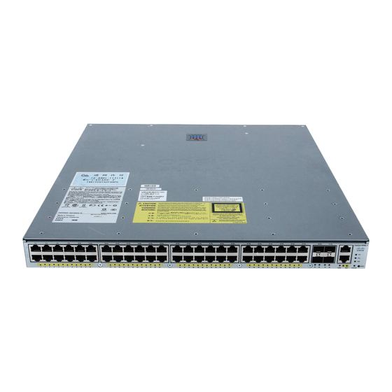
This chapter describes how to install the Catalyst 4948E switch in an equipment rack.
•
•
•
•
•
•
Before starting the installation procedures in this chapter, complete the site planning checklist in
Note
Chapter 2, "Preparing for Installation"
Preparing to Install the Chassis
This section covers these topics:
•
•
•
•
For additional information about the Cisco Catalyst 4948E and the Catalyst 4948E-F switches (including
Tip
configuration examples and troubleshooting information), see the documents listed on this page:
http://www.cisco.com/en/US/products/ps6021/tsd_products_support_series_home.html
OL-21561-02
Preparing to Install the Chassis, page 3-1
Rack-Mounting the Chassis, page 3-5
Installing the System Ground, page 3-10
Connecting Power to the Switch, page 3-12
Attaching the Interface Cables, page 3-15
Powering Up the Switch, page 3-21
Warnings, page 3-2
Verifying Package Contents, page 3-4
Required Tools, page 3-4
Lifting the Chassis Safely, page 3-5
C H A P T E R
to verify that all planning activities were completed.
Catalyst 4948E and Catalyst 4948E-F Switch Installation Guide
3
3-1
Advertisement
Table of Contents

Related Manuals for Cisco Catalyst 4948E


Summary of Contents for Cisco Catalyst 4948E
-
Page 1: Installing The Switch
C H A P T E R Installing the Switch Revised: January 4, 2012 This chapter describes how to install the Catalyst 4948E switch in an equipment rack. • Preparing to Install the Chassis, page 3-1 • Rack-Mounting the Chassis, page 3-5 Installing the System Ground, page 3-10 •... - Page 2 Do not work on the system or connect or disconnect cables during periods of lightning activity. Warning Statement 1001 Read the installation instructions before connecting the system to the power source. Statement 1004 Warning Catalyst 4948E and Catalyst 4948E-F Switch Installation Guide OL-21561-02...
- Page 3 Invisible laser radiation may be emitted from disconnected fibers or connectors. Do not stare into Warning beams or view directly with optical instruments. Statement 1051 Installation of the equipment must comply with local and national electrical codes. Statement 1074 Warning Catalyst 4948E and Catalyst 4948E-F Switch Installation Guide OL-21561-02...
-
Page 4: Verifying Package Contents
Carefully remove the chassis and accessory kit from the shipping container, and check each item for damage. If any item is missing or damaged, contact your Cisco representative or reseller for support. Return all packing material to the shipping container, and save it. -
Page 5: Lifting The Chassis Safely
Rack-Mounting the Chassis There are three rack-mount kits and one cable management kit available for both the Catalyst 4948E and the Catalyst 4948E-F switch chassis. Additionally, there is one optional inlet air duct kit that is available only for the Catalyst 4948E-F switch. -
Page 6: Attaching The Rack-Mount Brackets To The Chassis
19-inch (48.3 cm). This rack-mount kit is not suitable for racks with obstructions (such as power strips) that could impair access to the switch. If you are installing the Catalyst 4948E-F switch chassis in a hot isle and cold isle data center Note environment and plan on using the optional modular ToR switch inlet duct kit (Panduit model CDE2), you must install the rack-mount brackets to the front of the chassis. -
Page 7: Installing The Chassis In The Rack
While one person holds the chassis in place, secure the chassis to the rack with the four 10-32 x 3/4-inch Step 4 or the four 12-24 x 3/4-inch Phillips-head machine screws (two on each side) that are supplied in the accessory kit. Catalyst 4948E and Catalyst 4948E-F Switch Installation Guide OL-21561-02... -
Page 8: Installing The Cable Guide (Optional)
If the chassis is mounted to the rear posts of the equipment rack, the cable guide cannot be installed. Note Catalyst 4948E and Catalyst 4948E-F Switch Installation Guide OL-21561-02... -
Page 9: Installing The Catalyst 4948E-F Switch Chassis With The Optional Panduit Air Duct Kit
Duct Kit If you are installing the Catalyst 4948E-F switch chassis in a data center that is configured as hot isle and cold isle, you might need to install the Panduit Air Duct kit, Model CDE2. The kit extends the air intake from the rear of the chassis to the front of the equipment rack allowing the system to draw in cool air from the cool isle. -
Page 10: Installing The System Ground
Prepare the other end of the ground wire, and connect it to an appropriate earth ground point in your site Step 7 to ensure adequate earth ground for the switch. Catalyst 4948E and Catalyst 4948E-F Switch Installation Guide 3-10 OL-21561-02... - Page 11 7 - 3A 50 - 60 Hz INP UT OU TPU T Chassis grounding pad M4 screws (2X) System ground lug Adhesive label (yellow). Covers grounding pad. System ground wire Catalyst 4948E and Catalyst 4948E-F Switch Installation Guide 3-11 OL-21561-02...
-
Page 12: Connecting Ac Source Power To The Switch
Note Connecting AC Source Power to the Switch To connect source AC power to either a Catalyst 4948E or Catalyst 4948E-F switch, follow these steps: Verify that all of the site power and grounding requirements described in Chapter 2, “Preparing for Step 1 Installation”... -
Page 13: Connecting Dc Source Power To The Switch
If you have only one power supply installed in the chassis, you must cover the empty power supply bay Note with a blank power supply cover (Cisco p/n 800-25264-01). The blank power supply cover maintains EMI shielding and proper air flow through the chassis. - Page 14 Chapter 3 Installing the Switch Connecting Power to the Switch To connect source DC power to the DC-input power supply installed in the Catalyst 4948E switch, follow these steps: Verify that all of the site power and grounding requirements described in “Power Requirements”...
-
Page 15: Attaching The Interface Cables
Connecting to the Downlink Ports, page 3-16 Installing Uplink Port Transceivers and Cables, page 3-16 Connecting to the Ethernet Management Port, page 3-20 Connecting to the Console Port, page 3-20 Catalyst 4948E and Catalyst 4948E-F Switch Installation Guide 3-15 OL-21561-02... -
Page 16: Connecting To The Downlink Ports
Connect the RJ-45 plug at one end of the network cable to the target device port. Step 1 Connect the RJ-45 plug at the other end of the network cable to a downlink port on the Catalyst 4948E Step 2 chassis. - Page 17 Position the SFP transceiver in front of the socket opening. Step 5 Different Cisco devices have different SFP socket configurations. Your Cisco device could have Note either a latch-up or a latch-down orientation. Ensure that you are installing the SFP transceiver in the correct orientation for your Cisco device.
- Page 18 If the SFP transceiver cannot be removed, it is installed and seated properly. If the SFP transceiver can be removed, reinsert it and press harder with your thumb, repeating if necessary until it is latched securely into the socket. Catalyst 4948E and Catalyst 4948E-F Switch Installation Guide 3-18 OL-21561-02...
- Page 19 URL: http://www.cisco.com/en/US/tech/tk482/tk876/technologies_white_paper09186a0080254eba.shtml Remove the dust plugs from the SFP transceiver optical bores. Step 11 Immediately attach the network interface cable LC connector to the SFP transceiver. Step 12 Catalyst 4948E and Catalyst 4948E-F Switch Installation Guide 3-19 OL-21561-02...
-
Page 20: Connecting To The Ethernet Management Port
PC, use an RJ-45-to-DB-9 adapter cable (optional). To connect the PC or terminal to the Catalyst 4948E switch console port, follow these steps: Using an RJ-45-to-DB-9 adapter cable, insert the RJ-45 connector into the console port that is located Step 1 on the front of the switch. -
Page 21: Powering Up The Switch
PS2 LED is also lit green. If the LEDs are not green, refer to “300 W AC-Input Power Supply (PWR-C49E-300AC-R)” section on page A-1 “300 W AC-Input Power Supply (PWR-C49E-300AC-F)” section on page A-5 for additional LED descriptions. Catalyst 4948E and Catalyst 4948E-F Switch Installation Guide 3-21 OL-21561-02... - Page 22 • might be a problem with the target device. The POST failures are usually fatal. Call Cisco Systems if your switch does not pass the POST. Note For information on configuring the Catalyst 4948E or the Catalyst 4948E-F switch, refer to the appropriate software configuration guide at: http://www.cisco.com/en/US/products/ps6021/products_installation_and_configuration_guides_list.ht...
Need help?
Do you have a question about the Catalyst 4948E and is the answer not in the manual?
Questions and answers