Table of Contents
Advertisement
Quick Links
AOSENMA
CG035X
DUAL GPS
FOLLOW-ME QUADCOPTER
6-AXIS GYRO SYSTEM
OWNER`S MANUAL
("Translation" rewriting and compilation by Hendrik J Bosman
with critical inputs from Elio Bruce and other members of the
Aosemna CG035 Facebook Group)
Please read carefully before operating the craft. This Operating
Instruction Manual contains important safety information
Advertisement
Table of Contents

Summary of Contents for Aosenma CG035X
- Page 1 AOSENMA CG035X DUAL GPS FOLLOW-ME QUADCOPTER 6-AXIS GYRO SYSTEM OWNER`S MANUAL (“Translation” rewriting and compilation by Hendrik J Bosman with critical inputs from Elio Bruce and other members of the Aosemna CG035 Facebook Group) Please read carefully before operating the craft. This Operating...
- Page 2 Table of Contents (to be added later)
- Page 3 AOSENMA CG035 QUADCOPTER TECHNICAL DATA Technical specifications: Brand name: EACHINE CG035 Flight control frequency : 2.4G Channel : 4CH Gyro: 6 Axis FPV control frequency: 5.8G Motor Type: Brushless Motor 1806 2300KV Control Distance: 300m Remote Controller Power: 4 x 1.5V AA battery...
- Page 4 Failsafe Return to home when out of range Orbit feature,can orbit a specified point or location Follow me function, aircraft follows the remote controller, Arbitrary and easy manipulation. (Up, down, left right) Telemetry and mission planner by default. 2.4G Transmiter/ Easy Adjust Frequency 6 axis gyro system makes flight more stable and flexible Transmitter can be switched between Mode 1 (right hand throttle) and Mode 2 (left hand throttle)
- Page 5 1 x USB Charger 1 x Manual (Chinglish translation)
- Page 6 SAFETY PRECAUTIONS PLEASE READ AND HEED the following safety precautions. BATTERIES Never overcharge batteries as these may become excessively hot and explode. Always charge in a well ventilated area Use only designated batteries with designated balance chargers Dispose of batteries according to the legal requirements in your country Never put batteries in the fire Keep out of reach of small children...
- Page 7 OPERATION (FLYING AKA “PILOTING”) 1. Fly only in designated areas 2. Fly away from buildings and power lines 3. Fly away from people such as in a park 4. Fly away from animals 5. Fly away from water bodies and trees 6.
- Page 8 The Chinglish manual uses words and grammar that makes it completely useless in some instances. However through much support of YouTube videos and support from the AOSENMA CG035 Facebook community this manual will fulfil most users` needs. In actual fact the very comprehensive troubleshooting section by Elio Bruce is more complete than most other quadcopter manuals.
- Page 9 INTRODUCTION The AOSENMA CG035 Quadcopter is a toy grade quadcopter and designed for “playing” only. It is NOT suitable for commercial or serious hobby (such as racing) use. The above notwithstanding it is recommended that only persons with some RC experience use it or is available to teach novice pilots the correct way to setup and operate the controls.
- Page 10 IDENTIFICATION OF CONTROLS, PARTS AND FUNCTIONS Remote Controller functions ( picture and annotation by Duc RED Above pictures and annotation by Duc RED...
- Page 11 FLIGHT CONTROLS (by courtecy Elio Bruce) For those new to the CG035 and the world of drone flight in particular there are listed below the instructions on the use of the controller as well as functional details of all the buttons and switches.
- Page 12 is by default in mode 2, the differences are outlined below (importantly!) with the CG035 facing in the same direction you are: In both modes 1 and 2: Right stick: Left = Slide Left Right = Slide Right Left stick: Left = Rotate/Yaw Left Right = Rotate/Yaw Right.
- Page 13 Forward = away from you. Backwards = closer to you. Left stick: Forward = higher (throttle up). Backwards = lower (throttle down). IMPORTANT NOTE If you have the quadcopter facing towards you then sliding and forward/reverse controls are inverted in relation to you! Sliding to the left is accomplished by pushing left on the left stick, sliding right is moving the stick right!
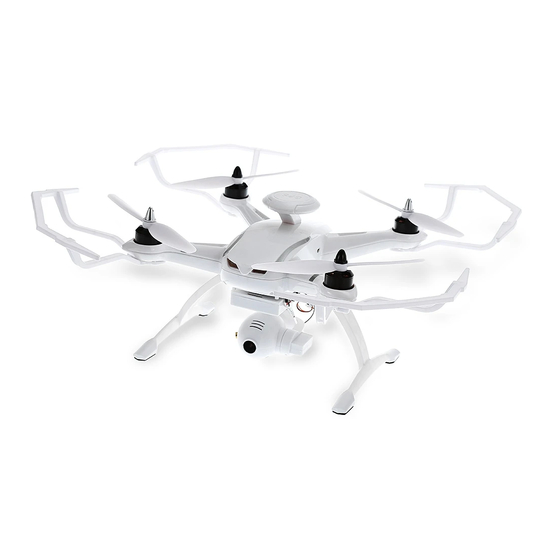
- Page 14 QUADCOPTER IDENTIFICATION OF PARTS Viewing the quadcopter from above. picture & annotation by Duc RED EXTREMELY IMPORTANT NOTICE It is extremely important to realise that the labeling of the motors on the schematic on page 4 of the Chinglish manual is CONFUSING because of the upside down and left to right view of the quadcopter from the bottom.
- Page 15 HOW TO ASSEMBLE Unpack all parts, cables and batteries from packaging. Check all parts, cables and batteries for damage that could cause failure and subsequent damage, or personal harm to people, of the quadcopter when in operation. The quadcopter comes with all electronics and motors pre-assembled.
- Page 16 identical it does matter which side it is assembled. Turn the quadcopter back to the normal position and stand it on the landing gear. Next up is the installation of the propeller guards. Propeller guards The above graphic is a composite with one guard installed.
- Page 17 The propeller guards needs to be assembled by pressing the thin guides into place. No screws needed. The original kit comes with 4 identical propeller guards which means that these are all interchangeable to be installed in any of the four positions. The quadcopter needs to be turned over with the underside in the up position in order to install the propeller guards.
- Page 18 To prevent the screws that hold the motors from vibrating loose and falling out just fill the plastic holder with liquid silicone. (photo and description by courtecy Rene Peerboom) Another way of preventing the screws from becomeing loose and falling out is by using “screw” glue such as Locktite Mild or plugging with light weight foam.
- Page 19 Propellers There are TWO sets of two propellers each. One set is designated as CW which is clockwise rotation and the other set is CCW which is counterclockwise rotation. It is important that the sets are installed on the correct motors as failure to do so may result in damage to the quadcopter and or the person operating the craft.
- Page 20 picture and annotation by Duc RED Install the CCW propeller blades, with the silver caps, onto motors M1 and M3 and tighten firmly by hand. Install the CW propeller blades, with the black caps, onto motors M2 and M4 and tighten firmly by hand. NOTE: However you may specifically want to leave that till after the calibration of the quadcopter and the remote controller after testing all functions as suggested by Elio...
- Page 21 Battery The above composite picture is the battery holder with the battery and all connecting wires and T-deans connectors inside. Note that the T-deans and charging wires are just an inset to try to show the connectors better. VERY VERY IMPORTANT NOTE ABOUT THE NEW BATTERY.
- Page 22 Before trying to install the battery into the quadcopter make sure that the foam that covers the T-deans connector is removed. If not done this way round the connection will most probably not be good and the quadcopter may either fail to start or fail during flight. Once the foam is removed make sure that the T-deans connecter is free of glue or other substances that could have an impact on the free flow of current between the...
-
Page 23: Remote Controller
INITIAL CALIBRATION PROCEDURE. (by courtesy Elio Bruce with some notes by Duc Red) It may be a good habit to calibrate the quadcopter before every flight session. Remote controller Calibration Push both sticks to upper left corners, hold while switching controller on. The red LED above the auto take off/land button should now flash. - Page 24 How to change between modes 1 and 2 (by courtesy Elio Bruce) Push both sticks to upper right corners and switch on the controller. Release sticks. Led above auto land/take off button should flash. Move right stick to the right to have right hand throttle (mode 1), or to the left for left hand throttle (mode 2) Led should now be solidly on.
- Page 25 The white LED's should now not be on and it will be only the red, green and blue eye lights once more. Switch everything off. Calibration is now complete. Notice that the 4 status lights should be off when OK.
- Page 26 PRE-FLIGHT CHECK Before a flight ALWAYS do a pre-flight check to insure that the quadcopter is ready to be operated safely. 1. Check that quadcopter is assembled correctly, check for parts that may have become loose during the last flight, 2.
- Page 27 FLYING THE AOSENMA CG035 (by courtecy Elio Bruce) Before attempting to fly the quadcopter insure that you are 100% familiar with the function of each control on both the remote controller and the quadcopter. This will insure that you are not surprised by unwanted maneuvers by the quadcopter whilst flying.
- Page 28 The following Android Apps are very usefull. GPS Test by Chartcross Ltd AndroiTS GPS Test Free by Alessandro Bonetti (My Personal favorite Duc RED) GPS Data by Propane Apps GPS Status & Toolbox by MobiWIA EclipSim IMPORTANT NOTE (by courtecy Elio Bruce) Be gentle with the controls on the first flight(s) to get used to the controls by doing simple manoeuvres such as short point to point take off and landings, slow banked...
- Page 29 1.5 meters from the ground, 9. Press the “ONE Key take-off/landing” button again and the quadcopter should land by itself, 10. CONGRATULATIONS YOU HAVE JUST COMPLETED YOUR FIRST SUCCESSFUL FLIGHT WITH YOUR AOSENMA CG035 QUADCOPTER!!. FOLLOW-ME Mode ORBIT Mode...
- Page 30 AOSENMA GROUND STATION SOFTWARE (by courtecy Jim Buxton) The software can be downloaded from the following link. http://www.drone-maniac.com/wp- content/uploads/2016/12/Aosenma_vast_gcs.zip ATTENTION & WARNING If used incorrectly the process WILL “brick” your quadcopter. The ground station software is provided by Hohem. ONLY use to tune PID`s, RTH, set maximum altitude and set the voltage alarm threshold for emergency landing.
- Page 31 Thought I would share my most recent experience with the CG035 "Ground Station Software" and how it resolved an issue with my CG035, and how this experience may be of some benefit to some members here. I have opened and used the software 5 or 6 times in the past 2 weeks, mainly just to modify the perimeters relative to the "Fly Function"...
- Page 32 see any visual changes in the graphic of my 035, so I decided to bail out. I disconnected from the computer, powered off the 035, turned off the transmitter and closed the program. To the back yard I go for a brief low level confirmation flight.
- Page 33 for such an obvious solution I know. But for me, it required curiosity and the "hobby addiction factor" to realize what should have been obvious to me in the beginning. I hope this can be of some benefit to others. The following paragraph is a reply from Jim Buxton to a question about using a phone app for leveling.
- Page 34 TROUBLESHOOTING (by courtecy Elio Bruce) This section assumes you have at least a passing familiarity with electronics, though I have tried to simplify things wherever possible to open the process to as many as possible. OK. Time for some fun and games. Let`s start with something simple.
- Page 35 DEAD ON ARRIVAL You have inserted the battery into the quad and nothing happens, no lights, no noise. This is known as CDOA or Completely Dead On Arrival. A few things can cause this issue. Best case scenario is that you have forgotten to remove the protective foam pad over the Deans T connector.
- Page 36 and inside the quad to ensure a good connection. There may be pieces of the pad or residue of glue that needs removed. Try using tweezers to remove the debris and lightly scratch the surfaces to take them back to bare metal. Another option is the LiPo battery has failed, either by physical damage or through being drained far past normal levels.
- Page 37 quality balance charger. A cell meter as shown above offers the information in a simpler way, just connect it to the balance charging port and it shows the voltage of each cell and the total of all cells Another possibility is THE CHARGER Could have failed and is only charging one cell or not at all.
- Page 38 The voltage on a correctly functioning stock charger (with no load) is measured as 4.8Volts across each cell. Pin 3 is ground (or – terminal, furthest right). Pin 2 is cell 1, pin 1 is cell 2. So if you put the negative probe of the multimeter on the negative pin of the charger and the positive probe of the meter on pin 2, you get a reading of 4.8V.
- Page 39 If none of these are the issue then the quad is more than likely dead and will need a new main flight board. Major surgery involved. Constant beeping from the controller. Low voltage indication. The right most led on the controller is flashing and the quad refuses to move.
- Page 40 Again a couple of potential issues here. The battery or charger may be damaged and not charging correctly, though still have enough charge to partly power the quad giving rise to the above condition. Test the battery and charger as outlined in the above DOA section. Another possibility is a faulty voltage sensor within the q uad or even the voltage reading not being transmitted correctly back to the controller.
- Page 41 Also the third light on the controller is flashing. This indicates the controller thinks the quad has had GPS failure (out of range warning), due to not receiving any GPS data. Check the quad and make sure there is a green light on under the GPS dome ofthe quad, if not then this is a known and common fault.
- Page 42 out all 22(!) screws and removing the props in order to access the bind button on the quadcopter.
- Page 43 The procedure to bind is as follows: Hold the bind button(circled in blue, above) down while inserting the battery on the drone, the led next to the button will now flash. Release the button. Next hold down the internal frequency aka bind button (circled in blue, across) on the controller then switching it on.
- Page 44 The flight board is the least probable cause of the problem unless all motors are affected. Thankfully. Remember to label or take a picture of all the positions of each wire and component you remove, this will help during reassembly! If you feel confident of a solution or have spare parts to hand then feel free to read on but skip ahead to sixth or even seventh test.
- Page 45 Next would be opening the chassis and carrying out an inspection of the wiring to the ESC and motor to see if there is a break there. A broken wire or intermittent connection can lead to false or incomplete signals to the ESC or motor giving erratic control and flight.
- Page 46 You can desolder the motor from the ESC and test each phase (wire windings inside the motor) in turn to see if they have a short to the stator (the bit of the motor that the wires come out of which stays stationary when on the quad) to determine if there is a short circuit.
- Page 47 A, B, C. What you are looking for here are two things, sound and heat, the motor should be more or less silent, just a gentle whirring noise or whistle with virtually no heat as it is not under load. If there is either of these it’s usually a mechanically dead motor and needs replaced.
- Page 48 desoldering and soldering the good motor back where the suspected bad one was. This way if you have to buy and fit a new motor you do not have to do this process twice. Spin the motors up to idle and see if there is any change.
- Page 49 If this does not isolate the issue then this would determine that the main flight board is the problem meaning it will need replaced. Not very expensive, all things considered, but a long, tedious and involved process. Note: Be careful if you need to order a replacement esc or motor (so far there seem to be two distinct versions of the esc and motor) as they should all match ratings and values otherwise there can be balancing and other issues...
- Page 50 Camera/Gimbal/FPV Transmitter unit Ok, is this actually worth mentioning? Right…. I suppose a few words of warning…? It is a diabolical contrivance and should be sentenced to death by fire. The tiny servo’s almost universally fail after a few flights, they never stay where they are pointed, the video quality is middling at best, especially as it is claimed to be 1080p and there are charging issues where the internal battery fails or has a poor connection.
- Page 51 It needs re designed from the ground up to be even half way capable. If it breaks down enough to make it unusable, remove it and replace with another system such as an action cam and mount if you want fairly good quality video recording (as shown above) and even with a connected FPV transmitter if you want or just replace with an all in one type of FPV camera/transmitter which can run from the...
- Page 52 lipo usb charger, not just a straight through power supply from a usb cable as it needs a dedicated charger to sense the voltage in the battery in order to cut off supply to it. You could then use this opportunity to replace the internal battery, if desired, with an external single cell one that you can remove to charge and wire on a JST or connector (or one of choice) to power up the camera and...
- Page 53 FPV MONITOR Not switching on. As with the camera this may be indicative of a failed USB charger, test it with your meter, it should output around 5.2V when plugged into a suitable USB power supply. If not, this needs replaced with a lipo charger, not just a straight through power supply from a USB cable as it needs a dedicated charger to sense the voltage in the battery in order to cut off supply to it.
- Page 54 Weak or ‘snowy’ picture at close (10meter or so) range Usually indicative of a faulty antenna, SMA connector or transmitter. An internally broken antenna can be annoying as it is essentially unfixable, having to buy a new one is the only realistic solution, however a couple of basic tests can usually determine where the fault lies.
- Page 55 However a further test can confirm if it is the antenna or if the monitor has an internal issue with it’s SMA socket. Simple if you have a spare antenna, swap it out and if it fixes the issue, problem solved. However if you do not then do as below.
- Page 56 Congratulations, you have just made a very basic 5.8GHz antenna. Insert it onto the hole being careful not contact the outer ground connection.
- Page 57 Re test the range, and if there is a marked improvement it confirms the antenna was the issue and needs replaced. If these tests show no improvement in signal then it will be an internal issue of the monitor or camera/transmitter. Again simple if you have another fpv system/spares as you can test parts against each other for comparison.
- Page 58 If not then the problem may be so deep it might not be worthwhile fixing, however you can try replacing the SMA socket or even just try re flowing the solder joints on the pins to see if that will fix it. A note for those beginners/intermediates interested in the Controller, Monitor and CG035 antenna mods: The stock antenna is pointing straight out inside the...
- Page 59 your transmitter I would suggest you start by fitting an external SMA socket which means you can screw onto it a whole raft of different commercially available third party antennas offering a wide range of claimed dB ‘boosts’. There are so many antenna mods you can do to improve range that if you research it there's practically no limit to them, hell you can even fit a wifi booster to it to increase the (wattage) output of the controller if you were so...
- Page 60 Think of your controller as a bulb producing a source of light and the antenna as a reflector and lens. Think of using the same power supply and the same 'bulb' giving out the same amount of light but projecting it in a different way..
- Page 61 A cloverleaf or mushroom type antenna projects out and up giving a more 'doughnut' shaped transmission, like a lantern. Good for all around flight but some height is sacrificed, particularly directly above you. Cloverleaf Mushroom Cloverleaf vs Mushroom antenna radiation pattern. A flat panel (patch or patch array) antenna projects everything almost all in one general direction like a floodlight.
- Page 62 in extreme cases. Almost entirely useless for flight control unless used with a ground station that can track your flight, only really used in fixed wing extreme range cases such as military UAV’s. So, each of these can be 'seen' progressively further away by the receiver.
- Page 63 If you need a graphic of this just google ‘antenna transmission pattern’ and that should show you what I mean. The claimed decibel (dB) increase of commercially available antennas rely on this principle and by having a precise calibration of the antenna to the correct frequency range and modifying the 'pattern' or focus of the transmission to give an increase in range.
- Page 64 precisely calibrated making the reading suspect at best, useless at worst. The current stock antenna used is a 'naked lightbulb' type, probably poorly calibrated, but ok for toy grade use. You can open the controller up and replace it with another better manufactured antenna.
- Page 65 specific channel's frequency range but it should be close enough to give good results. The next step up could be getting a hobby grade transmitter that you can programme for the CG035 frequencies and codes, but I personally don't know if anyone has been able to do that..yet, and a diversity receiver for FPV.
- Page 66 AOSENMA CG035 Facebook Group Notes & Tips How to disable the gimbal There are cases where the gimbal worked erratically or none at all. In these cases it may be necessary to disable the gimbal but not the camera. Unplug cables 2 and 3 of the gimbal from the quadcopter, leave 1 plugged in and you can still start and stop video recording and take photo`s.
Need help?
Do you have a question about the CG035X and is the answer not in the manual?
Questions and answers