Table of Contents

Summary of Contents for 2Y-LINK Technology CI-16-ASP-485
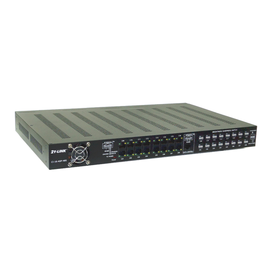
- Page 1 2Y-LINK Technology Simplifies Installation of High Quality CCTV System Intelligent Model Signal Processor User Manual 16 CHANNELS SIGNAL PROCESSOR CI-16-ASP-485 for transmission of Power, Video and Data(RS485) with Built-in Power Pack...
-
Page 2: Installation Environment
The package of 2Y-LINK Intelligent Model 16 Channels Signal Processor – CI-16-ASP-485 contents : Product contents One 16 Channels Signal Processor Unit One power cord (US, British, or EU) Signal Processor User Manual Note : This package is only one part of CCTV installation package, must work with the Associated Equipment for complete CCTV System. - Page 3 For instructions regarding the connection of the associated equipment in your system, please consult the User Manual of the 2Y-LINK Intelligent Model 16 Channels Signal Processor – CI-16-ASP-485 contents. Qualified Person to install this equipment This is not a DIY product.
- Page 4 Safety Precautions WARNING TO PREVENT FIRE OR SHOCK HARZARD, DO NOT CONNECT THE POWER CORD TO THE MAIN BEFORE CAREFULLY READ THE USER MANUAL ATTENTION : Installation should only be performed by qualified personnel only in accordance with national Electrical Code or applicable local code.
-
Page 5: Table Of Contents
5.4 For Power and Video Transmission USING BELL 31-32 CABLE Method of Wiring Connections for 16 Channels Signal 33-39 Processor CI-16-ASP-485 for Power, Video and Data (RS485) Transmission 6.1 For Power, Video and Data Transmission Using Cat.5 34-36 cable or in combination with bell cable 6.2 Transmission of Power, Video and Data for High Power... -
Page 6: Introduction Of 2Y-Link Technology
Chapter 1 Introduction of 2Y-LINK Technology 1.1 2Y-LINK Technology is a patented new concept, which has been successfully applied in the CCTV surveillance system with multi-functions, such as power, video, two-way audio, sensors, emergency signals and control data transmission, using a single pair of ordinary Bell Cable or an unshielded twisted pair of Cat.5 Cables between the Mixer at camera side... - Page 7 D. Different cable types can be used in mixed combination to achieve easy installation and cost reduction E. Commonly used wires and cables adopted by 2Y-LINK Technology for multi-functional application is shown in Fig 1.2. Fig.1.2...
-
Page 8: Features Of 16 Channels Signal Processor Ci-16-Asp-485
11. Compatible with 2Y-Link Push-Fit or Pig-Tail Mixers. 12. The 2Y-LINK Intelligent Model SIXTEEN Channels Signal Processor – Model No.CI-16-ASP-485 is also compatible with any DC 12V CCTV Camera up to 8W(680mA) with Video Output 1.0 Vpp 75 Ohm from any makers and produces equally... -
Page 9: Specifications Of Signal Processor Ci-16-Asp-485 And
Chapter 3 Specifications of CI-16-ASP-485 and associated Mixers 2Y-LINK - Two wires link up with Leeds Intelligent Model Signal Processor and Universal Mixers, and work well with different makers of CCTV cameras Specifications for Signal Processor CI-16-ASP-485 NO. of Channel... - Page 10 Chapter 3 Specifications of CI-16-ASP-485 and associated Mixers (continue) Specifications for Mixers Video In (from camera) 1.0 Vpp 75 Ohm Power Output for DC 12V 680 mA or Camera (up to 8W) AC/DC 24V 340mA As specified for the respective Mixer Model listed below...
-
Page 11: Product Overview
Chapter 4 Product Overview: 4.1 Signal Processor CI-16-ASP-485 BRIGHTNESS SHARPNESS SWITCH 87654 21 SHARPNESS + + + + + + + + RS485 RS485 ORANGE ORANGE WHITE CI-16-ASP-485 TO MIXER BRIGHTNESS Power DATA CONTROL Fig. 4.1.1 Front View Icon Item... - Page 12 Chapter 4 Product Overview: (continue) 180-260V ~ 50Hz CABLE TERMINALS TO MIXER C16~C13 C012~C09 87654 21 CAUTION DATA CAMERA CONTROL VIDEO OUT ONE CAT5 CABLE FOR 4 CAMERAS DO NOT OPEN Power FUSE: + + + + + + + + C08~C05 C04~C01 RATED 3A...
-
Page 13: Push-Fit And Pig-Tail Mixers
Chapter 4 Product Overview: (continue) 4.2 Push-Fit and Pig-Tail Mixers Push-Fit Mixer Fig.4.2.1 Pig-Tail Mixer Fig.4.2.2 Wiring connections of Push-Fit Mixer Wiring connections of Pig-Tail Mixer Fig.4.2.3 Fig.4.2.4... -
Page 14: Accessories For Easy Of Installation
Chapter 4 Product Overview: (continue) 4.3 Accessories for Easy of installation 4.3.1 Camera Distribution Boards Green/white Orange/white (Bridge wire) (Bridge wire) DB-4PF Distribution Board for four Cameras with Push-Fit Terminals Fig. 4.3.1.1 DB-4PF CAT.5 CABLE Wiring connections of DB-4PF Distribution Board for four Cameras with Push-Fit Terminals Fig. - Page 15 Chapter 4 Product Overview: (continue) Green/white Orange/white (Bridge wire) (Bridge wire) Connection to Camera DB-4RJ Distribution Board for Four Cameras with RJ45 Sockets Fig. 4.3.1.3 CAT.5 DB-4RJ CAT.5 CAT.5 CAT.5 CAT.5 CABLE Wiring connections of DB-4RJ Distribution Board for Four Cameras with RJ45 Sockets Fig.
- Page 16 Chapter 4 Product Overview: (continue) 4.3.2 Cable Converters CC-1RJ Cable Converter for Mixer with Push-Fit Terminals Fig. 4.3.2.1 CAT.5 CC-1RJ Wiring connections of CC-1RJ Cable Converter for Mixer with Push-Fit Terminals Fig. 4.3.2.2...
- Page 17 Chapter 4 Product Overview: (continue) CC-1PF Cable Converter with Push-fit Terminals Fig. 4.3.2.3 CC-1PF Wiring connections of CC-1PF Cable Converter with Push-fit Terminals Fig. 4.3.2.4...
- Page 18 Chapter 4 Product Overview: (continue) CC-2PF Cable Converter with Push-fit Terminals Fig. 4.3.2.5 PS-10KU Power Stabilizer Video Signal Cat.5 Cable Control Data Wiring connections for CC-2PF Cable Converter with Push-fit Terminals Fig. 4.3.2.6...
- Page 19 Chapter 4 Product Overview: (continue) 4.3.3 Power Stabilizer For cameras with operation current up to 680mA, if those Cameras do not have stablising circuit feature for a suddenly light change from a bright environment to dark environment a PS-10KU power stabilizer is normally required. PS-10KU Power Stabilizer Fig.
- Page 20 Chapter 4 Product Overview: (continue) 4.3.4 PF-ISO/PT-ISO Ground Loop Isolators For camera power rating over 8W or exceed the power rating of the Signal Processor, local power supply for the camera is required. If local power is supplied to the camera, the potential differences between the camera side and signal processor power point may occur and cause some moving horizontal lines on the CCTV monitor screen.
-
Page 21: Wiring Selection
Chapter 4 Product Overview: (continue) 4.4 Wiring Selection • The following table shows the necessary wire gauge for twin bell wire over the expected length between camera and CCTV Monitor. 150 mA PF068A12 PF068B12 PF068A24 PF068B24 PT068A12 PT068B12 AWG 20 500~1000m 500~1000m ≤500m... - Page 22 Chapter 4 Product Overview: (continue) 450 mA PF068A12 PF068B12 PF068A24 PF068B24 PT068A12 PT068B12 AWG 20 500m---600m -------- ≤500m ≤50m 1640ft---1970ft ≤1640ft ≤160ft CAT.5 -------- -------- -------- ≤200m ≤660ft Fig.4.4.4 Local Power for Camera 680 mA (See page 20 – Section 4.3.4 : Note 1 & 2) PF068A12 PF068A12 PF068B12...
- Page 23 Chapter 5 Methods of Wiring Connections for 16 Channels Signal Processor CI-16-ASP-485 for Power and Video Transmission 5.1 For Power and Video Transmission USING CAT.5 CABLE (One Cat.5 Cable for four Cameras) monitor CAT.5 CI-16-ASP-485 CAT.5 DB-4RJ CAT.5 CAT.5 CABLE CAT.5...
-
Page 24: Methods Of Wiring Connections For 16 Channels Signal
Chapter 5 Methods of Wiring Connections for 16 Channels Signal Processor CI-16-ASP-485 for Power and Video Transmission (continue) Wiring Connections for channels 1 to 4: 1. One end of the four pairs colour coded wires in each of the Cat.5 cable connects to a RJ45 plug as shown in Fig. - Page 25 Chapter 5 Methods of Wiring Connections for 16 Channels Signal Processor CI-16-ASP-485 for Power and Video Transmission (continue) (6) A short length of bell cable is connected between the “DC Power to Camera” Push-Fit Terminals and the Camera, while a short length of suitable cable is connected between the BNC Plug of the Push-Fit Mixer and the Camera as shown at A of Fig.
-
Page 26: For Power And Video Transmission Using Cat.5
Chapter 5 Methods of Wiring Connections for 16 Channels Signal Processor CI-16-ASP-485 for Power and Video Transmission (continue) 5.2 For Power and Video Transmission USING CAT.5 CABLE and IN COMBINATION WITH BELL CABLE (One Cat.5 Cable for four Cameras) monitor... - Page 27 Chapter 5 Methods of Wiring Connections for 16 Channels Signal Processor CI-16-ASP-485 for Power and Video Transmission (continue) Wiring Connections for channels 1 to 4: One end of the four pairs colour coded wires in each of the Cat.5 cable connects to a RJ45 Plug as shown in Fig.
- Page 28 Chapter 5 Methods of Wiring Connections for 16 Channels Signal Processor CI-16-ASP-485 for Power and Video Transmission (continue) Wiring Connection for other channels: 4. The wiring connections for channels 5 to 8, 9 to 12, and 13 to 16 are connected similarly as described in paragraphs 1 to 3 above.
-
Page 29: For Power And Video Transmission Using Cat.5
Chapter 5 Methods of Wiring Connections for 16 Channels Signal Processor CI-16-ASP-485 for Power and Video Transmission (continue) 5.3 For Power and Video Transmission USING CAT.5 CABLE (One Cat.5 Cable for one Cameras) AC Power Cord monitor INCREASE COLOUR/BRIGHTNESS SWITCH LEVEL (1 →... - Page 30 Chapter 5 Methods of Wiring Connections for 16 Channels Signal Processor CI-16-ASP-485 for Power and Video Transmission (continue) Wiring Connections for each channels 1. One end of the Cat5 cable is connected to the RJ45 plug with one pair of the colour coded Cat.5 wire white/orange and orange connected to Pins 1 and 2 respectively (for...
-
Page 31: For Power And Video Transmission Using Bell Cable
Chapter 5 Methods of Wiring Connections for 16 Channels Signal Processor CI-16-ASP-485 for Power and Video Transmission (continue) 5.4 For Power and Video Transmission USING BELL CABLE monitor CI-16-ASP-485 Fig. 5.4.1 Bell Cable Bell cable or Single pair of UTP Fig. - Page 32 Chapter 5 Methods of Wiring Connections for 16 Channels Signal Processor CI-16-ASP-485 for Power and Video Transmission (continue) Wiring Connections for each channel: 1. One end of the bell cable connects to one pair of the Video and Power 2-wire Terminals, ⑧...
-
Page 33: Method Of Wiring Connections For 16 Channels Signal
Chapter 6 Method of Wiring Connections for 16 Channels Signal Processor CI-16-ASP-485 for Power, Video and Data (RS485) Transmission A pair of bell cable/ Unshielded twisted pair cable/Cat.5 cable (UP TO 2000m) Video Signal Video Signal Signal TV monitor Mixer... -
Page 34: For Power, Video And Data Transmission Using Cat.5
Chapter 6 Method of Wiring Connections for 16 Channels Signal Processor CI-16-ASP-485 for Power, Video and Data (RS485) Transmission (continue) For Power, Video and Data Transmission Using Cat.5 cable or in combination with bell cable PS-10KU Power Stabilizer monitor CI-16-ASP-485... - Page 35 Chapter 6 Method of Wiring Connections for 16 Channels Signal Processor CI-16-ASP-485 for Power, Video and Data (RS485) Transmission (continue) Wiring Connections for each channel: 1. One end of the Cat5 cable is connected to the RJ45 plug with one pair of the colour coded Cat.5 wire white/orange and orange connected to Pins 1 and 2 respectively (for...
- Page 36 Chapter 6 Method of Wiring Connections for 16 Channels Signal Processor CI-16-ASP-485 for Power, Video and Data (RS485) Transmission (continue) Wiring Connections for Control Keypad: 7. For connection of the Control Keypad to the RS485 (Inlet RJ45 Socket) - item ④ in Fig.
-
Page 37: Transmission Of Power, Video And Data For High Power
Chapter 6 Method of Wiring Connections for 16 Channels Signal Processor CI-16-ASP-485 for Power, Video and Data (RS485) Transmission (continue) Transmission of Video and Data for High Power PTZ Camera (Power > 8 W) with Local Power Supply and Fitting of Isolator to the Mixer and Isolator Using Cat.5 cable or in combination with bell cable... - Page 38 Chapter 6 Method of Wiring Connections for 16 Channels Signal Processor CI-16-ASP-485 for Power, Video and Data (RS485) Transmission (continue) Wiring Connections for each channel: 1. One end of the Cat5 cable is connected to the RJ45 plug with one pair of the colour coded Cat.5 wire white/orange and orange connected to Pins 1 and 2 respectively (for...
-
Page 39: Method Of Wiring Connections For 16 Channels Signal
Chapter 6 Method of Wiring Connections for 16 Channels Signal Processor CI-16-ASP-485 for Power, Video and Data (RS485) Transmission (continue) Wiring Connections for Control Keypad: 7. For connection of the Control Keypad to the RS485 (Inlet, RJ45 Socket – item ④ of Fig. -
Page 40: Brightness / Sharpness (Colour) Switch Adjustment
Chapter 7 Brightness / Sharpness (Colour) Control Switch Settings 7.1 Control Switch Settings on the following Mixer models for transmission distance up to 500m. (1,640 ft.) Brightness/Sharpness Control Switch Push-Fit Mixers: - PF068A12 Universal Mixer for up to 500m, DC 12V 680mA to camera - PF068A24 Universal Mixer for up to 500m, AC/DC 24V 340mA to camera Pig-Tail Mixers - PT068A12 Universal Mixer for up to 500m, DC 12V 680mA to camera) - Page 41 Chapter 7 Brightness / Sharpness (Colour) Control Switch Settings (continue) 7.1.2 For wire length between 250 to 500 m (820 to 1,640 ft.) - (between the Mixer and Signal Processor) Depending on the choice of Camera, DVR, and Monitor, the users may wish to adjust the Sharpness (Colour) and Brightness of the images to suit their particular requirements.
- Page 42 Chapter 7 Brightness / Sharpness (Colour) Control Switch Settings (continue) 7.2.1 For wire length between 500 to 700 m (1,640 to 2,296 ft.) – (between the Mixer and Signal Processor) The built-in automatic alignment circuitry is designed to provide optimal high quality images in terms of Brightness and Sharpness (Colour) with all four Control Switches (Dip Switches) put to “LOWER”...
- Page 43 Chapter 7 Brightness / Sharpness (Colour) Control Switch Settings (continue) To further improve the Sharpness (Colour) and Brightness of the images, put the Control Switches (Dip Switches) 1, 2, 3, and 4 to “UPPER” position), as shown in Fig. 7.2.2.2. SHARPNESS UPPER Position------>...
- Page 44 Chapter 7 Brightness / Sharpness (Colour) Control Switch Settings (continue) 7.3.2 For wire length between 1,200 to 1,500 m (3,937 to 4,920 ft.) - (between the Mixer and Signal Processor) Depending on the choice of Camera, DVR, and Monitor, the users may wish to adjust the Sharpness (Colour) and Brightness of the images to suit their particular requirements.
-
Page 45: How To Mount The Signal Processor To 19" Rack
Chapter 8 How to mount the Signal Processor to 19” rack RM-16 ( a pair) RM-16 ( a pair) -
Page 46: Trouble Shooting
Chapter 9 Trouble Shooting Problems Possible Causes Corrective Actions 1 No video signal; The power rating of the To select suitable mixer model. No colour picture; camera and /or the Pictures in irregular transmission distance do not shape. match with the specifications of the Mixer specified on Page 10 of this manual. -
Page 47: Limited Warranty
LIMITED WARRANTY This product is warranted against defects in material or workmanship for the time periods Limited warranty covers only those defects that arise as a result of normal use of the product and does not cover any other problems, including those that arise as a result of: (i) improper maintenance or modification;...
Need help?
Do you have a question about the CI-16-ASP-485 and is the answer not in the manual?
Questions and answers