Advertisement
Quick Links
Download this manual
See also:
Instruction Manual
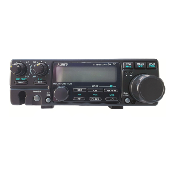
DX-70
Service Manual
•
S P E C I F I C A T I O N S ..................................................................................................................
•
C I R C U I T D E S C R I P T I O N .................................................................................................
•
S E M I C O N D U C T O R
•
E X P L O D E D V I E W ................................................................................................................
•
P A R T S
L I S T ..................................................................................................................................
•
A D J U S T M E N T .............................................................................................................................
•
P C B O A R D
•
B L O C K
D I A G R A M ....................................................... ........................................................
•
C I R C U I T D I A G R A M ...............................................................................................................
•
E D X - 1 ...................................................................................................................................................... 6 5
D A T A ...........................................................................................
V I E W ....................................................................................................................
1
2
1 2
2 1
2 8
4 2
4 9
5 8
5 9
Advertisement

Subscribe to Our Youtube Channel
Related Manuals for Alinco DX-70


Summary of Contents for Alinco DX-70
-
Page 1: Service Manual
DX-70 Service Manual • S P E C I F I C A T I O N S ........................• C I R C U I T D E S C R I P T I O N ....................•... - Page 2 1) General 2) Transm itter...
- Page 3 3) R eceiver...
-
Page 4: Receiver System
1. Receiver System 1) F ilte r U n it 2) M ain U n it... -
Page 9: Transmitter System
2. Transmitter System 1) Main Unit... - Page 10 2) PA U n it...
- Page 16 3) F ro n t U n it...
- Page 17 4) P L L U n it...
- Page 21 30.1M Hz...
- Page 23 5) Terminal function of CPU ‘ ’ ckx*...
- Page 24 SEG17 SEG17 Outpui io LCD Sequent SEG10 SEG16 Output 1 LCD Segment P7 7 SEG19 SEG19 Outpui to LCO Segmenl SEG20 SEG20 Outpui to LCD Segment P7-1 SEG?1 SEG21 Output lo LCD Segment SEG22 SEG?? Output to LCD Segment SEG23 SEG73 Output to LCD Segment SEG2d...
- Page 25 1) S7116A (XA0052) VDD=5.0V, CE1=V , CE2=V d d o...
- Page 26 2) MC3357 (XA0063) 3) M5218FP 4) NJM78L08UA (XA0075) U U U...
- Page 27 5) p.PC1241H (XA0079) ¡J.PC1241H 1 2 3 4 5 6 7 z z 5. 2 6) MC7808CT (XA0082) In p tr t i - --------- ■ > 4 fînm m on I [ _ __ x rtp iit 7) p.PD6345GS (XA0114) 15 Z Z] R E S 14 ZD SC K o>...
-
Page 28: Tc4S66F (Xa0115)
8) TC4S66F (XA0115) > 9) NJM2904M (XA0224) 10) BU4052BF (XA0236) y° [T (16) vee [ T V3(4) v s s [ T X : D o n ’t C a re... - Page 29 11) BU4094BF (XA0246) 8-Stage Shift Register 12) MC12019D (XA0292) 0 .8 1200 2 0 0...
- Page 30 13) MC74HC404QF (XA0293) 12-Stage Binary Ripple Counter 14) MC74HC390F (XA0294) >C — — 0 8 “ r" >...
- Page 31 15) MC14024BF (XA0295) 7-Stage Binary Counter rz z 16) MC14071BF (XA0296) Quad 2-Input OR Gate ; = £ > • : = D -...
-
Page 32: Pll Frequency Synthesizer
17) MB87086A (XA0297) PLL Frequency Synthesizer OSC* O S C L Z Z o u t R »’ L’ V -‘ H', Reference Divider Crystal oscillator Charge Pump & h... - Page 33 18) MB87014A (XA0298) PLL Frequency Synthesizer Pin Name Descnption Crystal connection terminal OSC'N Crystal connection terminal Phase comparator input monitor terminal Comparator divider output terminal Power supply Passive LPF connection terminal fr>fv: Dnve mode. Dop«'H'" fr-fv: High impedance !r<tv Sink mode. Oop-"L" GND terminal Phase detector output terminal Lo ck»"H U niock«negative pulse...
- Page 34 19) MC4001BF (XA0299) Quad 2-Input NOR Gate ; = t > - • ^ > - : = t > - : ; = £ > ■ ÏZ Z 20) AN612 (XA0300) 8 .6...
- Page 35 21) M5222FP (XA0385) Low Voltage Dual VCA IN2Q— £ - 22) LC75821W (XA0303) LCD Driver » ,...
- Page 36 23) BA4425F (XA0304) FM Front End IC 2 .6 20 0...
- Page 37 24) TC74AC74F (XA0305) 25) L78LR05B (XA0338)
-
Page 38: Voltage Regulator
26) MCT7805 (XA0346) 5V Voltage Regulator 27) TC4030BF (XA0347) inpul Output 3 0 - = E > - = E > " 28) 24LC16B (XA0351) ■ R/W control supply... - Page 39 PC1037GR (XA0379) Z Z 2 Z Z } -2 0...
-
Page 40: Transistor, Diode And Led Outline Drawings
30) Transistor, Diode and LED Outline Drawings... - Page 47 0 0 0 0 0 0 OOOOOOOC QCOOOO O 0 0 oooooooooooo OOOOOOOOOOOOO OOOOOOOOOOOOO oooocoooooooo OOOOOOOOOOOOO oooocoooooooo ooooooooooooo ooooooooooooo ooooooooooooo ooooooooooooo ooooooooooooo ooooooooooooo ooooooooooooo ooooooooooooo ooooooooooooo ooooooooooooo ooooooooooooo ooooooooooco ooooooooooo oooooooooo...
- Page 51 M A IN U n it...
- Page 52 M A IN U nit...
- Page 53 M A IN U nit...
- Page 54 M A IN U nit 1 22...
- Page 55 M A IN U nit...
- Page 56 M A IN U n it...
- Page 57 M A IN U nit...
- Page 58 M A IN U nit R222 H241...
- Page 59 M A IN U nit...
- Page 60 M A IN Unit/BPFl /BPF2...
- Page 61 M A IN Unii/BPF3/BPF4/BPF5/Conector Umt/Mic Umt/PLL U n it...
- Page 62 P L L U n it...
- Page 63 P LL U nit...
- Page 64 P LL U n it...
- Page 65 P L L U n it...
- Page 66 P L L U n it...
- Page 67 PU . Unit/VCOI Um t/VC02 U nit...
- Page 68 V C 02 Unit/VC03 U nit XD0233...
- Page 69 V C 03 Unit/NFB Unit/TO NE Unit/FiLT U nit U n it...
- Page 70 H LT U nit...
- Page 71 F ILT Umt/PA U nit 0010...
- Page 72 P A U n it 0201 0012...
- Page 73 P A Unit/JACK/FRO NT...
- Page 74 01011 1020 1001 1011...
- Page 75 0020 0020 0020 0020 0020...
- Page 76 F R O N T / VO L/'Speaker/O ther/'M echanical P a rts 0020 *1001 1002 111002 U P Q 28 7B 1 C S...
- Page 77 M e ch a n ica l Parts/Packing 0100 « p n w...
- Page 78 1) PA u n it A d ju s tm e n t 1. Digital voltage meter 2. DC current meter 300~500mA 3. DC regulated power supply 13.80V 25A or more (should be equipped with 20-25A current limit and'current meter) 4.
- Page 79 Adjustment the idle current without input signal. Adjust SWR at approximately 50W.
- Page 80 2) PLL A d ju s tm e n t 1. Digital voltage meter 2. DC regulated power supply 13.80V 5A or more 3. Frequency counter 500MHz or more 4. Spectrum Analyzer iG H z o rrn o re 5. Oscilloscope 100MHz or more □...
- Page 81 Measurement Adjustment item Equipment Unit Terminai Unit Parts Method VC01 CN90 PD1 = 1.2V Freq. Counter VC01 175MHz or above Frequency PDU4.3V 155MHz or below VC02 CN90 PDU1.5-4V VC02 Freq. Counter VC02 freq.: 71 MHz Frequency Attach the VCO to PLL, then adjust the unit after installing the PLL to the unit. VC02 f=7.100MHz Digital tester...
- Page 82 -£>■ Measurement Adjustment Condition H em Equipment Unit Terminal Unit Parts Method Frequency Freq. Counter RX LSB TC702 9873.60kHz +/- 0.02kHz (Mode) RX USB TC704 9876.40kHz / - 0.02kHz RX AM and FM TC703 9875.00kHz +/- 0.02kHz RX CWU Check 9875.80kHz +/- 0.3kHz RX GWL 9874.20kHz W- 0.3kHz...
- Page 83 1 Attach EJ26U to DX70. 2 When the subaudible Tone is ON in FM mode, adjust the unit according to following table. 3 When the subaudible Tone is OFF in FM mode, the tone should not be emitted. Measurement Adjustment Item Condition Equipment...
-
Page 84: Required Test Equipment
Required Test E quipm ent 1. D igital voltage meter 2. D C regulated power supply 13.80V 3A or m ore 3. SG about 200M Hz 4. Distortion meter, A F voltage meter 5. 8Q speaker 6. Oscilloscope 7. (N B adjustment tool) Main Unit A djustm ent Setting Main Unit A d ju stm e n t Points □... - Page 85 SG Output Frequency: 14.1000MHz Connect to HF Antenna Terminal. Frequency: 14.0993MHz Mode: USB RIT: OFF AGC: FAST NB: OFF RF Gain: +10dB AlF: Center Squelch VR: Turn the knob counterclockwise fully. Filter: Wide Measurement Adjustment Item Equipment Terminal Unit Parts Method Adjust every following group repeatedly to obtain the...
- Page 86 SG Output Frequency: 14.1000MHz Connect to HF Antenna Terminal. Frequency: 14.0993MHz Mode: USB RIT: OFF AGC: FAST NB: OFF RF Gain: +10dB AlF: Center Squelch VR: Turn the knob counterclockwise fully. Filter: Wide Measurement Adjustment Item Condition Equipment Terminal Unit Parts Method SG output: OdBn...
- Page 87 SG Output Frequency: 14.1000MHz Connect to HF Antenna Terminal. Frequency: 14.0S93MHz Mode: USB RIT: OFF AGC: FAST NB: OFF RF Gain: +10dB AlF: Center Squelch VR: Turn the knob counterclockwise fully. Filter: Wide Measurement Adjustment Condition Item Equipment Terminal Unit Parts Method SG output: 40dBn...
- Page 88 Required Test Equipm ent 1. D igital voltage meter 2. D C current meter 20-30A 3. D C regulated power supply 13.80V 25A or more (should be equipped w ith 20-25A current lim it) 4. Power meter 100W (1,9~30M H z) 10W (1,9~60M Hz or more ) 5.
- Page 89 Connect the power meter to HF antenna terminal. Frequency: 7.1000MHz Mode: USB Power. High Speech Compressor (SET mode): OFF FM-TONE: OFF Measurement Adjustment Item Equipment Terminal Unlit Parts Method Adjust to the maximum power. Slide S1 to rear panel (Adjust the AG input level so that Tuning side.
- Page 90 Connect the power meter to 50MHz antenna terminal. Frequency: 52.000MHz Mode: USB Power: High Speech Compressor (SET mode): OFF FM-TONE: OFF Measurement Adjustment Item Equipment Terminal Unit Parts Method Oscilloscope 50MHz Set the AM modulation factor to AG output: -30dBm Filter Li 1 (Linear...
- Page 91 Connect the power meter to HF or 50MHz antenna terminal. Frequency: 52.000MHz Mode: FM Power: High Speech Compressor (SET mode): OFF FM-TONE: OFF Measurement Adjustment Condition Item Equipment Terminal Parts Unit Method AG output: OFF ATT + 50MHz Balance the spurious to obtain Spurious Mode: FM spectrum...
- Page 94 U _XI u _ u » r C fC U [Q) ,-fl. E-fl R , j t j j lacaEE MO (EE ¿813 s tea ED •isaED Bt*30 Z D O r-O -n tE • ¿ C W g~ ~ P m m 9 s r ’...
- Page 95 100U16V PD09A09M P122AQ5M CP602 TBP- P01X-AÎ . VRfiOl 220 0603 2SC1972 — . 0 6 0 2 - L - * : "-1 — j — ZBF2530 JP J25 45- 01 - 510 JPJ254S 0 1 - 510 J602...
- Page 96 i S Q ? s g ROSS ‘•“ co m s i r ¿ é ™ ñ n ™ 7 Ü Z D...
- Page 97 C N J C V J ■ < J c*> I f c r> — r>- CN509 P122A05M...
- Page 98 * !>!!., . 5 ? f w E B S g g njfT$^ara.» v f 1 - o il- C * L = g | ..B iD c S fe HLS4198 ' - ^ 1 y am '• * 3 * „...
- Page 99 T Z 0 0 5 6 J J U U T CN702 OOOO B6B-ZR bhje U X 1 0 8 7...
- Page 100 Ar x r? i3 7 4HC4040 2 2 * e y y s w r y...
- Page 101 ? ? ' l ' i i i i i i i i i i i i...
- Page 102 E x p l o d e d V i e w f o r E D X - 1...
- Page 103 ST0054...
- Page 104 BLACK PINK...
- Page 105 AJ0017 AJ0017 AJ0017...
- Page 106 C V 0 0 0 1...
- Page 110 P a r t s L i s t f o r E D X - 1 Ref. Ref. Parts No. Parts Name Parts No. Parts Name Tuner RDI 013 JPK02 R01 CU3047 C1608JB1H103KT-A RD1013 JPK02 R01 16MV10SZ CE0201 RDI 013 JPW02 R O T CE0201 16MV10S2...
- Page 111 EDX - 1 Tuner Ref. Ref. Parts No. Parts Name Parts Name Parts No. RK3050 ERJ3GSYJ103V RKQ001 ERJ6GEYJ100V RK3026 ERJ3GSYJ101V R3Û RK3070 ERJ3GSYJ474V ERJ3GSYJ101V RK3026 ULÛ SVR-12 UL0015 SVR-12 UQ0D15 SPPJ22727A SW 2 UR0013 SRRY101AN-R15 SW 3 US0020 ESDI 522209 CT0036 ECV12IT20X64T CV0001...
- Page 112 S upplied co-ax cable...
- Page 113 METER TX ON BAND METER TX TUNE ANT TUNE UNIT READING 14.1MHz 100W 14.1MHz THRU 100W 100W 14.1MHz THRU (100W on scale) 1.9MHz 1.5max. 100W 3.6MHz 1,5max. 100W 7,1MHz 1.5max. 100W 10 1MHz 1.5max. 100W 14.1MHz 1,5max. 100W 18.1MHz 1.5max. 100W 21.1MHz 1,5max.
- Page 114 PC Bord View for EDX S vi SPPJ2-CN-PV...
- Page 115 __ „„Sfa R301HC C 9|33 0 P C n 9 V T '7m ,*nU>m »0 m i m Z l9 ’^ I O h S s i 0. 47U83V . C I S 0 . 0 t...
- Page 116 S c h e m a t i c D i a g r a m f o r E D X - 1...
Need help?
Do you have a question about the DX-70 and is the answer not in the manual?
Questions and answers