
Subscribe to Our Youtube Channel
Summary of Contents for Frick RWB II Plus
- Page 1 S70-200 OM/DEC 99 File: SERVICE MANUAL - Section 70 Replaces: S70-200 OM/MAR 99 Dist: 3, 3a, 3b, 3c OPERATION - MAINTENANCE MICROPROCESSOR CONTROL...
-
Page 2: Table Of Contents
MICROPROCESSOR OUTPUT DATA CODES ........................14 MICROPROCESSOR OUTPUT DATA CODE ..........................15 MICROPROCESSOR TELECOMMUNICATIONS ........................16 COMMUNICATIONS PROTOCOL SPECIFICATIONS: ....................... 16 TROUBLESHOOTING THE RWB II PLUS MICROPROCESSOR ....................20 GENERAL INFORMATION ................................. 20 TROUBLESHOOTING FRICK SBC MICROPROCESSOR SYSTEM ..................20 TESTING MICRO-PANEL ALARMS/CUTOUTS ......................... 23 EPROM MEMORY I/C CHIP REPLACEMENT ........................... -
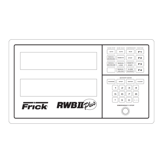
Page 3: Microprocessor Control Panel
STOP BUTTON IS FOR EMERGENCY SHUTDOWN SITU- ATIONS ONLY and MUST NOT BE USED TO ROUTINELY The RWB II PLUS compressor is controlled by a state-of- SHUT OFF THE COMPRESSOR. the-art microprocessor control system. The microprocessor continuously monitors the compressor unit’s condition and... -
Page 4: Keys And Key Functions
S70-200 OM RWB II PLUS MICROPROCESSOR CONTROL Page 4 OPERATION display mode. To change to a different display mode, press KEYS AND KEY FUNCTIONS the [CHANGE] key. The display modes in their order of rota- tion are: NOTE: The microprocessor will automatically return to the main operating display after 60 seconds of keybo- 1. - Page 5 RWB II PLUS MICROPROCESSOR CONTROL S70-200 OM OPERATION Page 5 COMPRESSOR - Compressor displays the status of the NOTE: Consult Motor Manufacturer for the recom- compressor unit. The mode of operation will be indicated as mended duration of the Recycle Delay.
-
Page 6: To Change The Adjustable Setpoints
S70-200 OM RWB II PLUS MICROPROCESSOR CONTROL Page 6 OPERATION ID - The ID number is a programmable identification code Cycle Time - Cycle time is the amount of time between the used in telecommunications to access a specific compres- beginning of each load/unload response. -
Page 7: How To Determine Adjustable Setpoints
RWB II PLUS MICROPROCESSOR CONTROL S70-200 OM OPERATION Page 7 PRELUBE, FULL LUBE, or CYCLING - Pump type will be HOW TO DETERMINE indicated. ADJUSTABLE SETPOINTS: PGM/ - Microprocessor Program version. Adjustable Setpoints should reflect values compatible with normal system operation. Too high a Low Suction Pressure LIQ INJ CON - The Liquid Injection Control, reported in de- Alarm setpoint may cause nuisance prealarms. - Page 8 S70-200 OM RWB II PLUS MICROPROCESSOR CONTROL Page 8 OPERATION 4. Press [F1] to call up the Operating display. If the condi- ANNUNCIATOR DISPLAY * tions causing the alarm have not been corrected or a new ANNUNCIATOR: PG-1 Thu 10-01-87 15:33:36...
- Page 9 DISABLED COMMAND WAS SELECTED, THE ACCESS tion, the compressor will return to the previous mode of op- CODE IS [00000]. eration. LOST OR FORGOTTEN ACCESS CODE: Consult Frick ANALOG OFFSET DISPLAY* Company for assistance. ANALOG OFFSET: Disch Oil Sep Filt Spare Econ...
-
Page 10: Temperature-Pressure Control Program (Option)
2, 5, 10, 15, 20, or 25 percent. the Temperature-Pressure Control Program option has been ordered with the RWB II Plus Rotary Screw Com- DB - The Dead Band (DB) is a + (plus) or - (minus) value pressor Unit. - Page 11 RWB II PLUS MICROPROCESSOR CONTROL S70-200 OM OPERATION Page 11 SUCTION PRESSURE - Constantly monitors and displays TEMPERATURE-PRESSURE CONTROL the suction pressure in pounds per square inch gauge (g) PROGRAM (OPTION) (continued) or inches of mercury (hg). The new setpoints provided on this display allow monitor-...
-
Page 12: Lead-Lag Option
S70-200 OM RWB II PLUS MICROPROCESSOR CONTROL Page 12 OPERATION be greater than or equal to the “START” setpoint in order to The timer only accumulates time whenever the pressure start the compressor. This setpoint works in conjunction with drops to or below the “STOP” setpoint and will reset if the the “TIMER”... -
Page 13: Communications Troubleshooting
Troubleshooting the communications: Go to the FIXED SETPOINTS PAGE by using the “CHANGE” The Frick microprocessor has 4 major components and a key and the “ * ” key. The display will appear as: variety of sensors. The major components are the SBC... -
Page 14: Multiple Compressor Sequencing
S70-200 OM RWB II PLUS MICROPROCESSOR CONTROL Page 14 OPERATION A typical example of how the microprocessor responds can MULTIPLE COMPRESSOR SEQUENCING be illustrated by the responses generated by the micropro- FOR RWB II COMPRESSOR UNITS WITH cessor as oil temperature increases. Assume that the ambi-... -
Page 15: Microprocessor Output Data Code
MICROPROCESSOR OUTPUT DATA CODE A 3.5 K OHM, 10 watt resistor (RES) must be field installed, as shown below, when the 120 VAC outputs of the RWB II PLUS are driving 120 VAC solid state input devices such as programmable controllers. -
Page 16: Microprocessor Telecommunications
Returned answer: A01 terface with your compressors. Character Description The Frick RWB II PLUS Microprocessor comes with an on Position of returned data board telecommunications interface. The telecommunica- Acknowledge of command sent. - Page 17 RWB II PLUS MICROPROCESSOR CONTROL S70-200 OM OPERATION Page 17 COMPRESSOR DISPLAY SCREENS COMMAND: #01DXN RETURN TEMPERATURES COMMAND: #01TX Start command sequence. Start command sequence. Compressor ID code. Compressor ID code. Compressor control command. Return temperature command. X = 0 Operating display.
- Page 18 S70-200 OM RWB II PLUS MICROPROCESSOR CONTROL Page 18 OPERATION QUERY SETPOINTS DATA - #IDQ2 will return CHANGE SETPOINTS COMMAND: #01C # Byte(s) Setpoint (Name/Comment) Start command sequence. Compressor ID code. 1,2,3 Future Change setpoint command. 4,5,6 Future xxx New setpoint...
- Page 19 RWB II PLUS MICROPROCESSOR CONTROL S70-200 OM OPERATION Page 19 CHANGE COMPRESSOR MODE COMMAND: ADDITIONAL DISPLAY DUMP COMMAND: #IDMCmlD Change mode to m. #IDD1 Will dump SETPOINTS PAGE 1 (new display) O=off A=autocycle R=remote #IDDS Will dump ADJUSTABLE SETPOINTS (std Return message - “A”...
-
Page 20: Troubleshooting The Rwb Ii Plus Microprocessor
RWB II PLUS unit. The section is composed of will go blank. four parts: a general information section, a troubleshooting... - Page 21 RWB II PLUS MICROPROCESSOR CONTROL S70-200 OM MAINTENANCE Page 21 TROUBLESHOOTING FRICK SBC MICROPROCESSOR SYSTEM (Continued) SYMPTOM PROBABLE CAUSES and CORRECTIONS OIL PUMP IS RUNNING BUT THE The (HAND-OFF-AUTO) Oil Pump Selector Switch (1SS) controls oil pump operation COMPRESSOR DOES NOT START and must be in the AUTO position before the compressor can be started.
- Page 22 REMOTE MODE. If 120VAC is found (across Wires 21 and 2, 22 and 2, and 23 and 2) and the input does not turn on, consult Frick Company. MOTOR LOAD CONTROL The current transducer is used to convert the AC motor amps to a DC voltage (FORCED UNLOAD) OCCURS signal for the microprocessor.
-
Page 23: Testing Micro-Panel Alarms/Cutouts
RWB II Frick Rotary Screw Compressor Unit with a RWB II Plus microprocessor. They should Hi Oil Temp Alarm / Cutout only be completed by a competent individual with full understanding of safe operating procedures as they 1. - Page 24 NOTE: The oil level cutout is not present on units with full lube pumps. If you are unsure of the pump type on your unit, contact Frick Service for confirmation. Dirty Filter 1. Push the [+/-] key and record the Oil Pressure value from the analog offset display (Example: +2).
-
Page 25: Eprom Memory I/C Chip Replacement
RWB II PLUS MICROPROCESSOR CONTROL S70-200 OM MAINTENANCE Page 25 5. If the gray/yellow wires are not present on the old SBC, EPROM MEMORY I/C CHIP REPLACEMENT the machine is equipped with a new style display. Resistor R6 must be removed from the new board by cutting the wire Microprocessor EPROM memory I/C chips are located in- leads on either side of the resistor. -
Page 26: Sbc Wiring Diagram
S70-200 OM RWB II PLUS MICROPROCESSOR CONTROL Page 26 MAINTENANCE SBC WIRING DIAGRAM POWER BATTERY SUPPLY PORT PORT DIG I/O EXPANSION FRICK REV D RWBII PLUS ANALOG EXPANSION DIGITAL INPUT DIGITAL OUTPUT MODULES MODULES FUSES FU1 - FU6 12 13 14... -
Page 27: Micro Component Placement Diagram
COMPRESSOR #2 COMMUNICATIONS PORT: AC-422 PORT #1 PORT #1 AC-422 Asychronous Adapter Card Pinout RWB II PLUS MICRO Ports 1 and 2 Pinout Ground Ground - RX (Receive) - CTS (Clear To Send) + RX (Receive) + CTS (Clear To Send) -
Page 28: Micropanel Assembly Wiring Diagrams
POWER SOURCE ALL POWER SOURCES SHALL BE GROUNDED ON ONE SIDE -ISOLATED AND SEPARATED FROM OTHER INDUCTIVE LOADS SUCH AS LIGHTING CIRCUITS -OR FROM FRICK SUPPLIED OR SPECIFIED STARTER, USE MINIMUM #12 AWG FOR FEED ALL NEUTRALS ENTERING NEUTRAL IF SEPARATE FEED OR VOLTAGE FOR HEATER CIRCUIT IS DESIRED, THIS ENCLOSURE SHALL REMOVE JUMPERS 1 TO 1A &... - Page 29 NOTE A: IF COMPR. MOTOR STARTER IS A FRICK SUPPLIED STARTER OR CONFORMS TO FRICK STARTER SPECS, WIRE AS SHOWN ON LINE 60 ONLY. JUMP TERM 6 TO 36. IF 2CR IS USED AS A ISOLATED CONTACT, WIRE AS SHOWN BETWEEN THE HOT &...
- Page 30 S70-200 OM RWB II PLUS MICROPROCESSOR CONTROL Page 30 MAINTENANCE MICROPANEL ASSEMBLY WIRING DIAGRAM...
- Page 31 RWB II PLUS MICROPROCESSOR CONTROL S70-200 OM MAINTENANCE Page 31 MICROPANEL ASSEMBLY WIRING DIAGRAM #22 AWG TWISTED PAIR 2000 FT. MAX. DISTANCE WHITE (CHANNEL 5) TE-5 BLACK BLACK SPARE TEMP REMOTE TEMPERATURE CABLE #5 CAPACITY CONTROL (OPTIONAL) WIRING BY OTHERS...
-
Page 32: Recommended Spare Parts - Current Design
S70-200 OM RWB II PLUS MICROPROCESSOR CONTROL Page 32 MAINTENANCE RECOMMENDED SPARE PARTS - CURRENT DESIGN ITEM DESCRIPTION QTY. MODELS ITEM NUMBER SBC SINGLE BOARD COMPUTER ASSY. (REV D) 333Q0000547 INPUT MODULE (120 VAC) 333Q0000116 INPUT MODULE (220 VAC) 333Q0000789...
Need help?
Do you have a question about the RWB II Plus and is the answer not in the manual?
Questions and answers