Table of Contents
Advertisement
Available languages
Available languages
DATASHEET
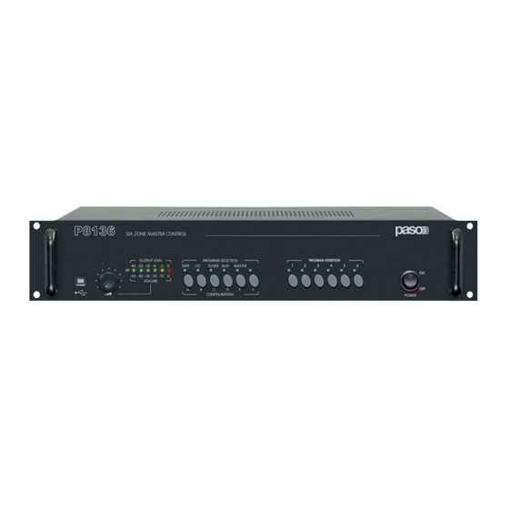
Pannello di controllo 6 zone master
Nel ringraziarVi per aver scelto un prodotto PASO, vogliamo ricordarVi che la nostra azienda opera con sistema di qualità
certificato. Tutti i nostri prodotti vengono pertanto controllati in ogni fase della produzione per garantirVi la piena soddisfazione
del Vostro acquisto. Per ogni evenienza la garanzia coprirà, nel periodo di validità, eventuali difetti di fabbricazione. Vi
raccomandiamo di leggere attentamente le seguenti istruzioni d'uso per sfruttare appieno le prestazioni offerte da questo
prodotto e per evitare eventuali problemi.
INDICE DEI CONTENUTI
1.
Riferimenti numerati .................................................................................................................................... 2
2.
Avvertenze generali ..................................................................................................................................... 3
2.1
Installazione ........................................................................................................................................... 3
2.2
Alimentazione e messa a terra ................................................................................................................. 3
2.3
Note di sicurezza..................................................................................................................................... 3
3.
Introduzione ................................................................................................................................................. 3
4.
Glossario e criteri generali ........................................................................................................................... 4
5.
Soluzioni di impianto di diffusione sonora .................................................................................................. 4
5.1
Impianto con amplificazione a singolo canale voce/musica ......................................................................... 5
5.2
Impianto con doppia amplificazione per i canali Voce e Musica separati ...................................................... 7
5.3
Impianto con amplificazione dedicata per ciascuna zona ............................................................................ 8
5.4
Impianto con amplificazione mista a gruppi multipli ................................................................................... 9
6.
Uso .............................................................................................................................................................. 10
6.1
Selezione ingresso musicale ................................................................................................................... 10
6.2
Postazioni microfoniche PMB106/PMB112 ............................................................................................... 10
7.
Software di gestione P8136 Manager ....................................................................................................... 12
7.1
Operazioni preliminari ........................................................................................................................... 12
8.
Montaggio a rack ........................................................................................................................................ 13
9.
Caratteristiche tecniche ............................................................................................................................. 13
IMPOSTAZIONI E REGOLAZIONI ................................................................................................ 15
1. Regolazioni ed impostazioni Master .............................................................................................. 15
2. Funzioni Slave ............................................................................................................................ 17
3. Scheda riproduttore di messaggi ACMG8136 ................................................................................. 19
4. Scheda d'espansione ACIO8136 ................................................................................................... 20
SEZIONE B
COLLEGAMENTI ........................................................................................................................... 22
• Collegamento delle sorgenti musicali ............................................................................................. 22
• Collegamento delle sorgenti agli ingressi VOX ................................................................................ 22
• Collegamento amplificatori/diffusori ............................................................................................... 23
• Collegamento postazioni microfoniche e schede ACIO8136.............................................................. 25
• Collegamenti tra master e slave .................................................................................................... 27
SEZIONE C
LIMITI DI SISTEMA ..................................................................................................................... 28
• Istruzioni per l'uso •
P8136
Advertisement
Chapters
Table of Contents

Summary of Contents for Paso P8136
-
Page 1: Table Of Contents
Pannello di controllo 6 zone master P8136 Nel ringraziarVi per aver scelto un prodotto PASO, vogliamo ricordarVi che la nostra azienda opera con sistema di qualità certificato. Tutti i nostri prodotti vengono pertanto controllati in ogni fase della produzione per garantirVi la piena soddisfazione del Vostro acquisto. -
Page 2: Riferimenti Numerati
α DATASHEET RIFERIMENTI NUMERATI Pannello di controllo master P8136 (18) Morsettiera ingresso musica zone 1÷3. Connettore USB. (19) Morsettiera uscita zone 1÷3. Controllo volume. (20) Connessione tra master. Indicatore livello di uscita VuMeter/Volume. (21) Morsettiera uscita zone 4÷6. Selezione ingresso musicale TAPE e relativa regolazione volume. -
Page 3: Avvertenze Generali
Collegare la spina di rete (12) dell’apparecchio alla rete elettrica utilizzando l’apposito cavo fornito in dotazione; assicurarsi che la presa di corrente sia dotata di collegamento di terra a norma di legge. Il circuito di alimentazione del P8136 è protetto da un fusibile situato sulla spina di rete dell’apparecchio. -
Page 4: Glossario E Criteri Generali
I conflitti di chiamate delle Unità Master connesse allo stesso P8136, sono regolati secondo i criteri di priorità del chiamante: una chiamata in corso può essere interrotta solo da una a priorità strettamente maggiore. - Page 5 (e/o le schede ACIO8136), connesse in cascata tra loro, possono essere collegate come: Unità Master alla presa TO MASTER UNITS (24) oppure come Unità Locali alla presa TO LOCAL UNITS (30) del P8136. Infine, i master e gli slave sono messi in comunicazione tra loro tramite cavi cat.
- Page 6 Selezionare l’indirizzo degli slave a partire dallo 0 (considerando anche quello contenuto nel P8136). Impostare il numero di gruppo a 0 a tutti gli slave . Impostare la modalità di funzionamento di tutti gli slave - compreso quello contenuto nel P8136 - su single (vedi APPENDICE, Sez. A - pag. 18).
- Page 7 Le impostazioni sono indentiche a quelle del precedente paragrafo 5.1, con eccezione del punto 3: Collegamento Unità Master Impostare la modalità di funzionamento di tutti gli slave - compreso quello contenuto nel P8136 - su dual (vedi APPENDICE, Sez. A - pag. 18) Collegamenti Master/Slave...
- Page 8 • Anche in questo caso, ove sia necessario disporre di una potenza complessiva superiore a quella di un amplificatore da 500W (massimo taglio della gamma PASO) è possibile utilizzare più amplificatori come esposto nei suggerimenti del par. 5.1. • Per gli slave con zone in cui non sia prevista la musica di sottofondo, non è necessario cablare i morsetti M. (18) e (23).
- Page 9 P8136 5.4 Impianto con amplificazione a gruppi multipli Questa configurazione è un’applicazione delle 3 precedenti 5.1 – 5.2 – 5.3 che mostra la possibilità di dimensionare l’impianto secondo molteplici esigenze: • dividere fisicamente l’installazione in più sottosistemi localizzati in posti distanti tra loro;...
-
Page 10: Uso
PTT o premere nuovamente il tasto LOCK. Premendo il tasto ALL sulla postazione principale, viene eseguita la chiamata generale delle 36 zone collegate al master P8136: il led del tasto PTT lampeggia velocemente ad indicare questa tipologia di chiamata. Una volta terminata la chiamata generale, premere nuovamente il tasto ALL per riportare la postazione allo stato iniziale. - Page 11 P8136 • LED di segnalazione linea occupata Postazione Locale In condizioni di riposo il LED è spento. Durante una chiamata in corso il LED è acceso fisso a segnalare la propria postazione attiva. Dalla condizioni di riposo il LED lampeggia lentamente a segnalare una chiamata in corso da parte di un’altra postazione, che impegna almeno una zona del proprio gruppo di appartenenza.
-
Page 12: Software Di Gestione P8136 Manager
Al termine della procedura guidata, verrà creata un’icona sul desktop. Inizializzazione 1) Collegare il PC al P8136 tramite l’apposita presa USB (1) presente sul frontale del master con il cavo in dotazione; 2) Accendere il master portando in posizione ON l’interruttore di rete POWER (11);... -
Page 13: Montaggio A Rack
P8136 MONTAGGIO A RACK Montare l’apparecchio a rack tramite le apposite viti (A) e le rondelle (B), come indicato nella figura. CARATTERISTICHE TECNICHE P8136 Alimentazione da rete 230 V - 50/60 H Consumo da rete 23 W Alimentazione esterna in c.c. -
Page 14: Appendice
• Regolazione volume di uscita generale del canale musica • Selezione della sorgente sonora e regolazione del livello di ingresso • Invio della musica selezionata verso i master P8136 remoti • Attivazione/disattivazione della musica nelle singole zone • Chime master (attivo per le postazioni collegate alla presa TO MASTER UNITS) •... - Page 15 Tramite la tastiera PROGRAM SELECTION (4÷9) è possibile impostare e regolare i principali parametri del pannello di controllo master P8136. É inoltre possibile salvare l’ultima configurazione desiderata o richiamare la precedente configurazione in memoria a seguito di eventuali modifiche non desiderate.
- Page 16 α Appendice DATASHEET Impostazioni e regolazioni Sezione A • Attivazione/disattivazione della musica nelle singole zone *SW* Per attivare la diffusione di musica di sottofondo in una o più zone, è sufficiente premere il relativo pulsante della tastiera PROGRAM INSERTION (10). La conferma della selezione viene visualizzata dal led relativo: Led acceso = musica ON ;...
- Page 17 2. FUNZIONI SLAVE (tastiera PROGRAM INSERTION) • Indirizzo unità slave all’interno del master P8136 L’impostazione di fabbrica prevede che l’unità Slave del P8136 abbia indirizzo 0; questo indirizzo NON DEVE ESSERE DIVERSO DA ZERO per nessun motivo. E’ possibile tuttavia controllare, ed eventualmente correggere, l’impostazione di fabbrica: Per entrare in programmazione, premere contemporaneamente i tasti 1 e 2;...
- Page 18 α Appendice DATASHEET Impostazioni e regolazioni Sezione A • Modalità SINGLE/DUAL Per entrare in programmazione, premere contemporaneamente i tasti 1 e 4; il led 6 inizia a lampeggiare. Il led 1 visualizza la modalità attualmente impostata: Led spento = Modalità SINGLE (amplificazione unica per voce/musica) Led acceso = Modalità...
-
Page 19: Scheda Riproduttore Di Messaggi Acmg8136
• Installazione della scheda ACMG8136 Dopo aver tolto il coperchio (34) sul retro del P8136 svitando le due viti laterali, inserire la scheda ACMG8136 nel vano e collegarla all’apparecchio tramite il cavo flat a 14 conduttori. Fissare la scheda al pannello posteriore del master riutilizzando le viti precedentemente rimosse. -
Page 20: Scheda D'espansione Acio8136
• Unità Locale , collegata a TO LOCAL UNITS (30) dei pannelli Slave Capogruppo – (modalità slave ). La scheda ACIO8136 in modalità Master , opera secondo la programmazione effettuata tramite il software di sistema P8136 Manager. Per ogni contatto di ingresso possono essere definiti: •... - Page 21 Appendice Impostazioni e regolazioni Sezione A • Negativo comune dei contatti optoisolati di ingresso Le porte dei contatti di ingresso optoisolati possiedono un capo (cui fa riferimento il polo negativo della tensione di pilotaggio) in comune tra loro, mentre l’altro capo è connesso direttamente alla morsettiera di ingresso a 6 poli (41); il capo in comune può essere connesso direttamente alla massa della scheda tramite il ponticello CN101 (J5) in posizione A oppure reso disponibile sul morsetto (40) della scheda con il ponticello in posizione B.
-
Page 22: Collegamento Delle Sorgenti Musicali
Segnale P8136 attraverso le prese MASTER LINK IN/OUT (20): è possibile regolare il volume di ingresso di ciascuna sorgente per bilanciarne i livelli e regolare il volume generale del canale musicale selezionato. -
Page 23: Collegamento Amplificatori/Diffusori
Appendice Collegamenti (2) Sezione B COLLEGAMENTO AMPLIFICATORI/DIFFUSORI Per il collegamento a lato ingresso amplificatore riferirsi al relativo manuale, tenendo conto che il collegmento riporta segnali di tipo sbilanciato a livello di linea. • Impianto con amplificazione a singolo canale voce/musica (vedi par. 5.1) Collegare la presa di uscita MIX OUT (27) all’ingresso di linea dell’amplificatore;... - Page 24 α Appendice DATASHEET Collegamenti (2) Sezione B • Impianto con amplificazione dedicata per ciascuna zona (vedi par. 5.3) Collegare la presa di uscita MIX OUT (27) ai morsetti SP (17) e (22) in parallelo. Collegare la presa di uscita MUSIC OUT (26) ai morsetti M. (18) e (23) in parallelo. Utilizzare cavi schermati rispettando le polarità...
-
Page 25: Collegamento Postazioni Microfoniche E Schede Acio8136
• Lunghezza massima della linea di collegamento tra P8136/P8236 e l’ultima Unità Locale: 1 km. • Lunghezza massima della linea A di collegamento tra P8136 e l’ultima Unità Master: 1 km (se le unità vengono distribuite sulle 2 linee A, il dato è... - Page 26 Collegamenti (3)(4) Sezione B Il P8136 dispone internamente di 2 ponticelli dedicati all’impostazione del carico di fine linea per l’ingresso TO MASTER UNITS, in dipendenza del numero di linee collegate alle prese LINE A e LINE B. La regolazione è necessaria soprattutto nei casi di collegamento su lunghe distanze (da circa 200-300m in poi).
-
Page 27: Collegamenti Tra Master E Slave
Il master P8136 e gli eventuali slave P8236 sono connessi tra loro per mezzo del collegamento SLAVE LINK IN/OUT (33); questo consente lo scambio dei dati tra gli slave e mette in comune il segnale audio delle Unità Master connesse al P8136. SLAVE LINK (33) porta sia il segnale audio delle postazioni master sia il segnale musicale della sorgente selezionata sul P8136. - Page 28 α Appendice DATASHEET Limiti di sistema Sezione C...
- Page 29 Appendice Limiti di sistema Sezione C...
- Page 30 Nota La PASO S.p.A declina ogni responsabilità per danni a cose e/o persone derivanti dall’uso non corretto dell’apparecchio o da procedure non rispondenti a quanto riportato sul presente libretto. Nel continuo intento di migliorare i propri prodotti, la PASO S.p.A. si riserva il diritto di apportare modifiche ai disegni e alle caratteristiche tecniche in qualsiasi momento e senza alcun preavviso.
- Page 31 6-zone Master Control Panel While thanking you for having chosen a PASO product, we would like to remind you that our company works according to a certified Quality System. This means that all our products are checked during every phase of manufacturing in order to ensure that you will be fully satisfied with your purchase.
-
Page 32: Numbered References
α DATASHEET NUMBERED REFERENCES P8136 Master Control Panel (18) Music input terminal strip, zones 1 to 3. USB connector. (19) Output terminal strip, zones 1 to 3. Volume control. (20) Connection between master units. VuMeter/Volume output level indicator. (21) Output terminal strip, zones 4 to 6. -
Page 33: General Notice
Connect the mains plug (12) of the equipment to the power mains using the cable included in the supply for this purpose. Make sure that the power outlet has a regulation connection to earth. The power circuit of the P8136 is protected by a fuse installed on the mains plug of the equipment. -
Page 34: Glossary And General Criteria
Conflicts between calls from Master Units connected to the same P8136 are governed on the basis of caller priority: a call in progress can only be cut off by one with a higher priority. - Page 35 ACIO8136 cards), connected to one another in cascade fashion, can be connected either as Master Units to the TO MASTER UNITS socket (24) or as Local Units to the TO LOCAL UNITS socket (30) of the P8136. Lastly, the master and the slave are placed in communication with one another by means of Cat.
- Page 36 Tips • If an overall output power exceeding that of a 500W amplifier (the largest in the Paso range) is required, it is possible to use more than one amplifier. The inputs should be connected in parallel to the MIX OUT output (27) of the slave unit with the address 0; the output of each amplifier will be used to drive a sub-group of zones having an overall output power compatible with the rated power of the amplifier.
- Page 37 The settings are identical to those described in section 5.1 above, with the exception of point 3: 3. Set the operating mode of all the slaves – including the one contained in the P8136 Master units connection – to dual (see APPENDIX, Section A - page 18).
- Page 38 Tips • Again in this case, if an overall output power exceeding that of a 500W amplifier (the largest in the Paso range) is required, it is possible to use more than one amplifier, as described in the tips for section 5.1.
- Page 39 P8136 5.4 System with amplification according to multiple groups This configuration is an application of the 3 illustrated above in sections 5.1, 5.2 and 5.3, showing that it is possible to size the system depending on a number of needs: •...
-
Page 40: Use
Once the call has been completed, release the PTT key or press the LOCK key again. If the ALL key on the main station is pressed, all 36 zones connected to the master P8136 will be called: the LED of the PTT will flash rapidly to indicate this type of call. Once the All Call has been Any output events associated with the selected zones will be carried out for the whole duration of the call. - Page 41 P8136 • Line busy signalling LED Local Station In the idle condition the LED is OFF. While a call is in progress the LED remains steady ON to signal that the station is active. From the idle condition the LED starts to flash slowly to signal that a call is in progress by another station, that has seized at least one zone of the...
-
Page 42: P8136 Manager Software
An icon will be created on the desktop upon completion of the guided procedure. Initialisation 1) Connect the PC to the P8136 via the USB socket (1) provided for this purpose on the front panel of the master unit using the cable included in the supply;... -
Page 43: Rack Mounting
P8136 RACK MOUNTING Mount the equipment on a rack using the screws (A) and washers (B) provided, as illustrated in the figure. TECHNICAL SPECIFICATIONS P8136 Mains power 230 V - 50/60 H Mains power absorption 23 W External DC power supply... -
Page 44: Appendix
• Adjustment of VOX activation threshold • Setting the address of the P8136 Master Unit 2. Slave Functions • Address of slave unit within the P8136 master unit • Group • SINGLE/DUAL mode • Local chime (active for stations connected to the TO LOCAL UNITS socket) 3. - Page 45 A quick guide to the main manual controls accessible to the user for both common use and configuration settings is provided below. Using the PROGRAM SELECTION keypad (4 to 9), it is possible to set and adjust the main parameters of the P8136 Master Control Panel. It is also possible to save the last configuration or to return to the stored previous configuration if unwanted changes have been made.
- Page 46 α Appendix DATASHEET Settings and Controls Section A • Activation/de-activation of music in the single zones *SW* To activate broadcasting of background music in one or more zones, simply press the appropriate button on the PROGRAM INSERTION keypad (10). Your selection will be confirmed by the relevant LED: LED ON = music ON ;...
- Page 47 Fig. A9 2. SLAVE FUNCTIONS (PROGRAM INSERTION keypad) • Address of slave unit within the P8136 master unit The address of the Slave Unit is factory set at 0. This address MUST NOT BE OTHER THAN NOUGHT under any circumstances.
- Page 48 α Appendix DATASHEET Settings and Controls Section A • SINGLE/DUAL mode To enter the programming mode, press keys 1 and 4 at the same time. LED 6 will start to flash. LED 1 will show the current mode setting: LED OFF = SINGLE mode (single amplification for both speech and music) LED ON = DUAL mode (separate speech and music amplification).
- Page 49 • Installing ACMG8136 card Remove the cover (34) from the rear of the P8136 after unscrewing the two lateral screws, then insert the ACMG8136 card into the compartment and connect it to the equipment by means of the 14-lead flat cable. Use the screws just removed to secure the card to the rear panel of the master unit.
-
Page 50: Acio8136 Expansion Card
• as a Local Unit, connected to the TO LOCAL UNITS socket (30) of a group-leader slave unit – ( slave mode). In the Master mode, the ACIO8136 card functions on the basis of the programming carried out by means of the P8136 Manager system software. - Page 51 Appendix Settings and Controls Section A • Common negative of the optoinsulated input contacts The ports of the optoinsulated input contacts have one end (to which the negative pole of the driving tension refers) in common with each other, while the other end is connected directly to the 6-pole input terminal strip (41).
-
Page 52: Connections
(33). By enabling the music output on a remote Master Unit, it will be possible to send the program that has been selected to other P8136’s of the system via the MASTER LINK IN/OUT sockets (20). This output is not affected by the general volume control. -
Page 53: Connection Of Amplifiers/Speaker Units
Appendix Connections (2) Section B CONNECTION OF AMPLIFIERS/SPEAKER UNITS For connections on the amplifier input side refer to the amplifier manual, keeping in mind that the connection provides signals of the unbalanced type at line level. • System with amplification of a single speech channel/music (see point 5.1) Connect the MIX OUT output socket (27) to the line input of the amplifier. - Page 54 α Appendix DATASHEET Connections (2) Section B • System with dedicated amplification for each zone (see point 5.3) Connect the MIX OUT output socket (27) in parallel to terminals SP (17) and (22), then onnect the MUSIC OUT output socket (26) in parallel to terminals M.
-
Page 55: Connection Of Microphone Stations And Acio8136 Cards
• Maximum length of the line between the P8136/P8236 and the last Local Unit: 1 km. • Maximum length of the A line between the P8136 and the last Master Unit: 1 km (if the units are distributed along the 2 “A” lines, this distance refers to the sum of the lengths of the 2 lines). - Page 56 Connections (3) (4) Section B The P8136 has two dedicated internal jumpers for setting the end-of-line load for the TO MASTER UNITS input, depending on the number of lines connected to the LINE A and LINE B sockets. Adjustment is necessary above all in the event of connections over long distances (about 200-300 m upwards).
-
Page 57: Connections Between Master And Slave
Slave Units and places the audio signal of the Master Units connected to the P8136 in common. The SLAVE LINK (33) carries both the audio signal of the master stations and the music signal of the source selected on the P8136. In systems with no P8236 slave units the SLAVE LINK connection (33) is not used. -
Page 58: System Limits
α Appendix DATASHEET System Limits Section C... - Page 60 The warranty does not cover products that are improperly used or installed, mechanically damaged or damaged by liquids or the weather. If the product is found to be faulty, it must be sent to Paso free of charges for shipment and return. This warranty does not include any others, either explicit or implicit, and does not cover consequential damage to property or personal injury.
Need help?
Do you have a question about the P8136 and is the answer not in the manual?
Questions and answers