Table of Contents

Related Manuals for Upgrading everyday security SecuPlace WiFi

Summary of Contents for Upgrading everyday security SecuPlace WiFi
-
Page 1: Quick Start Guide
SecuPlace WiFi Quick Start Guide Visit us on the Web: www.riscogroup.com For detailed installation and system information, refer to the full installation manual at: http://www.riscogroup.com/products/products/953 iOS app Android app RISCO Group website... -
Page 2: Table Of Contents
Table of Contents GETTING STARTED ....................... 4 ......................4 OMPONENTS ....................4 XPANDING YOUR YSTEM ....................... 4 YSTEM NSTALLATION IMPORTANT SAFETY PRECAUTIONS ................5 INITIAL SYSTEM SETUP ....................6 STEP 1: SIM INSTALLATION AND CONTROL PANEL WIRING ......... 7 SIM C .................... - Page 3 )............ 28 SSIGNING DITING ELETING SERS ODES ................29 ESIGNATING A OLLOW UMBER STEP 9: ESTABLISHING SYSTEM COMMUNICATION ..........29 ................... 29 OMMUNICATION HANNELS Connecting to GPRS / GSM ................... 29 Editing the APN ..................... 30 ..................... 31 ONNECTING TO Selecting your WiFi Network: ................
-
Page 4: Getting Started
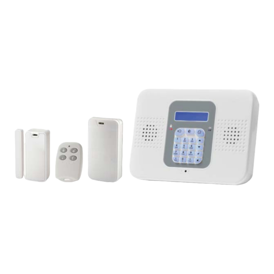
Getting Started Kit Components Control Panel The control panel communicates with all system detectors and accessories, with the alarm receiving centre, and with users via Cloud-based Smartphone and Web-browser applications. Detectors Detectors generate alarm events upon intrusion detection. Magnetic door / window contact detectors serve to protect doors and windows, while PIR (Passive Infra-Red) motion detectors serve to protect designated zones. -
Page 5: Important Safety Precautions
Important Safety Precautions WARNING: Installation or usage of this product that is not in accordance with the intended methods as described in the instructional materials and by the supplier can result in damage, injury, or death. WARNING: Make sure this product is not accessible by children and those for whom system operation is not intended. -
Page 6: Initial System Setup
Initial System Setup The following steps are required to initially set up your system for operation: Step 1: SIM Installation and Control Panel Wiring Step 2: Installing the Control Panel Step 3: Powering Up the Control Panel Step 4: Selecting a Language Step 5: Registering Components Step 6: Installing Kit Components Step 7: Testing the System... -
Page 7: Step 1: Sim Installation And Control Panel Wiring
Step 1: SIM Installation and Control Panel Wiring WARNING: Make sure the control panel is NOT connected to an electrical power supply when performing SIM installation and wiring. WARNING: Make sure to comply with all applicable electrical code and regulations. CAUTION: If your system does not have a SIM card pre-installed, install it before applying electrical power to the control panel. -
Page 8: Wiring At The Control Panel
Wiring at the Control Panel To perform wiring at the control panel: 1. Make sure the control panel is NOT connected to an electrical power supply, and then open it as follows; both covers remain connected to each other with a ribbon cable (do not detach): Remove and retain the screw on the cover. - Page 9 2. At the back side of the control panel, route the AC power cable through the wiring outlet: Tamper switch location (on opposite side) Screw mounting grooves SIM card access cover Wiring outlet ...
- Page 10 5. At the terminal block connect wire leads for the relevant connections, as required: AC power supply terminals Cable clamp Terminal block. Connection terminals from left to right: external module, PGM, zone (for a single hard-wired peripheral), GND.
-
Page 11: Step 2: Installing The Control Panel
Step 2: Installing the Control Panel Mounting Guidelines When installing, make sure the control panel is: Accessible to all external connections for electrical power supply and additional (non-kit) RISCO Group components. In a central location, in relation to the wireless components your system will be using, with a minimal distance from the components ... -
Page 12: Installation Procedure
Installation Procedure WARNING: Make sure the control panel is NOT connected to any electrical power supply. To install the control panel: IMPORTANT: When mounting, although the screws enter the control panel’s elbow grooves in the center as shown below, the screw holes / screws must be positioned at the upper-most location on the elbow grooves:... -
Page 13: Step 3: Powering-Up The Control Panel
Step 3: Powering-Up the Control Panel After performing all wiring tasks at the control panel, installing the SIM card, and installing the control panel, you can now power-up the control panel. NOTE: After initial power-up, any subsequent removal of the control panel from the wall will trigger a tamper alarm. -
Page 14: Step 4: Selecting A Language
Step 4: Selecting a Language Upon initial control panel power-up, you will be prompted to select the language and default options. To select a language: 1. At first installation, after control panel power-up, SELECT LANGUAGE displays on the keypad. 2. -
Page 15: Step 5: Registering Components
Step 5: Registering Components All components used in your system (detectors, keyfobs, and other wireless devices) must be registered in order to be recognized by the system. Registering Kit Components Your kit comes with pre-registered components. Perform the following to complete the registration process. -
Page 16: Registering Additional Components
Registering Additional Components For additional components added to your system, register them as follows: NOTE: For additional keyfobs, see Registering Keyfobs, page 16. To register additional components: Remove the component cover. 2. At the control panel, press and hold for about 3 seconds (disregard the ENTER USER CODE message) until REGISTER and TRANSMIT 1 display. -
Page 17: Deleting Component Registrations
4. Press to save the registration, or press to cancel. 5. Register the next device, or if finished, press to exit the registration mode. Deleting Component Registrations If you no longer use a system component, you must “delete” its registration to the control panel. -
Page 18: Step 6: Installing Kit Components
Step 6: Installing Kit Components Pre-Installation Planning Before installing system components, to ensure optimal system performance, determine which areas need to be protected and the best locations for installing the components. -
Page 19: Installing The Magnetic Door / Window Contact Detector
Installing the Magnetic Door / Window Contact Detector The magnetic door / window contact detector has two parts – a transmitter, and a magnet. It can be installed at the entry / exit door of a secured site, to a window, a sliding door, or at any similar entrance that could be accessed by an intruder. -
Page 20: Installation Procedure
Installation Procedure NOTE: If the transmitter is installed using adhesive strips, the back tamper switch will not be operational. NOTE: For installing the transmitter with adhesive strips, skip to step 3B in the following procedure. To install the transmitter and magnet:... - Page 21 -OR-...
-
Page 23: Installing The Pir Detector
Installing the PIR Detector The wireless PIR (Passive Infra-Red) detector detects movement for up to 11 metres (36 feet) indoors. The Pet immunity (PI) model is designed to not trigger alarms by small pets that weigh up to 36 kilograms (80 pounds). Mounting Guidelines Avoid mounting a PIR PI detector in a location where... -
Page 24: Installation Procedure
Installation Procedure To install a PIR detector: Tamper switch DIP swtich Battery holder... - Page 25 Wall mount Corner mount NOTE: Retain the screw for use when re-installing the PCB An additional battery (purchased separately) can also be used to extend the operational duration (size ½ AA, 3.6 V, lithium). Check the RISCO Group website for information on battery updates.
-
Page 26: Step 7: Testing The System
Step 7: Testing the System It is recommended to test all system components (kit-supplied and additional) to ensure correct operation. Performing a Keyfob Test Test keyfobs by pressing the arming / disarming buttons to observe whether the respective chimes are heard, and whether the control panel display indicates arming/disarming. -
Page 27: Step 8: Defining System Users
Step 8: Defining System Users The system supports up to 31 users, and each user needs to be assigned a unique 4-digit user code. A valid user code is required to perform most system operations. NOTE: Controlled codes communicate system commands to the alarm receiving centre, whereas non-controlled codes do not communicate system commands to the alarm receiving centre. -
Page 28: Assigning, Editing, And Deleting Users (User Codes)
Assigning, Editing, and Deleting Users (User Codes) System users (user codes) are typically designated from RISCO Cloud (see Step 10: Connecting to , page 32). Alternatively, they can be assigned from the control panel. NOTE: At initial system installation, it is highly recommended that the master user and engineer edit their default codes to be ones that are unique and confidential. -
Page 29: Designating A Follow Me Number
Designating a Follow Me Number You can designate the cell phone number of a system user to receive SMS Follow Me notifications of system events. To designate a Follow Me number: At the control panel, press and then enter the master code (default is 1234) or the engineer code (default is 1111). -
Page 30: Editing The Apn
Editing the APN The APN connects automatically, however in certain circumstances there may be a need to manually edit the APN definitions. Before manually editing the APN, you need to disable Auto APN. To disable Auto APN: 1. At the control panel keypad, press and then enter the engineer code (default is 1111). -
Page 31: Connecting To Wifi
Connecting to WiFi To connect via WiFi , you must select your router’s WiFi network. NOTE: Your router’s WiFi must be activated in order for the control panel to recognize and communicate with the router. Selecting your WiFi Network: To select your WiFi network (if not yet selected): 1. -
Page 32: Step 10: Connecting To Risco Cloud
Step 10: Connecting to RISCO Cloud After connecting to GPRS, register first in order to log in to RISCO Cloud. Registering to RISCO Cloud To register to RISCO Cloud: 1. Go to www.riscocloud.com/register 2. Complete all the required fields: ... -
Page 33: Logging In To Risco Cloud
4. Press REGISTER. 5. To complete registration, the user must open the e-mail message received (at the e-mail address defined as the Login name), and then click the link. Logging in to RISCO Cloud You can also log in to RISCO Cloud from your Smartphone (see Using the Smartphone and Web Applications, on page 39). -
Page 34: Operating The System
Operating the System Before You Start Using the System After completing all initial system setup steps, before you use the system, first check if any trouble messages still display on the control panel (use to scroll and view). If any remain, see Troubleshooting on page 40. Describing the Control Panel Keypad Keypad buttons Description... -
Page 35: Describing The Control Panel Leds
Describing the Control Panel LEDs Color State Status Both AC electrical power and battery power are disconnected System power status is ok (no Green system trouble) Open (activated) zone. Check that the windows and doors are Green Flashing closed and no movement is OK LED detected by the detectors within the protected area. -
Page 36: Describing User Commands
Describing User Commands Commands to control and use the system (such as arming and disarming) are typically performed by system users at the control panel, keyfob, as well as via the Smartphone and Web-browser applications. Describing Arming Modes Full arm: Partial arm: Perimeter arm: For arming premises... -
Page 37: Performing Commands From Control Panel And Keyfob
Performing Commands from Control Panel and Keyfob Command Control Panel Procedure Keyfob Procedure Full arm Press Press . Then, if prompted, enter user code. Partial arm Press . Then, if prompted, enter user code. Press Perimeter arm Press Press . Then, if prompted, enter user code. Disarm (and Enter user code Press... -
Page 38: Sending Sms Commands
Sending SMS Commands Command Description SMS Command Code Disarm Full arm Partial arm Perimeter arm Receive system arming status (master user only) To send a command by SMS: From your cellular phone, enter text (in the order as shown in this example): Command Description User Code... -
Page 39: Using The Smartphone And Web Applications
Using the Smartphone and Web Applications Smartphone App The Smartphone RISCO Cloud app will guide you through the operational instructions. Download from the Apple’s App Store for iOS devices, or from Google Play for Android devices. iOS app Android app Web Application For operational instructions, refer to the RISCO Cloud Web application documentation at:... -
Page 40: Troubleshooting
Troubleshooting The following are a list of trouble messages that may appear on the control panel display, along with actions the user can perform for resolution. Trouble Message Description Corrective Action Component has been Return component to its install removed (or moved) location (mounted in the correct TAMPER ALARM... - Page 41 Trouble Message Description Corrective Action The cellular network is The cellular network needs to be down, reception is not restored, the control panel needs to adequate, or the SIM card be relocated to a place with better MEDIA LOSS GSM has a depleted usage reception, or the SIM card usage allowance.
- Page 42 Trouble Message Description Corrective Action All zones have been In order to arm the system, bypassed (the system ALL ZONES unbypass one or more of the cannot be armed in this BYPASSED zones. condition).
-
Page 43: System Maintenance - Battery Replacement
System Maintenance — Battery Replacement The user can replace batteries for keyfobs, detectors and other accessories. Check the RISCO Group website for battery updates. WARNING: Ensure a battery is replaced with the correct type and polarity. Do not recharge, disassemble, deform, expose to high heat, or incinerate batteries. -
Page 44: Replacing Component Batteries
Replacing Component Batteries When replacing batteries in detectors and other system accessories, do the following to prevent activating the sounder: To replace component batteries: From the control panel, press for about 3 seconds until REPLACE BATTERY displays. 2. Remove the dead battery, and then insert the new battery; the tamper alarm is activated as usual, but the sounder does not sound. -
Page 45: Product Specification
Product Specification General Wireless zones (wireless RF technology) Hard-wired zone Wireless keyfobs Wireless repeaters (range extenders) 2-way wireless sounder User codes Arming methods full, partial, or perimeter Event log capacity (time & date stamped) 1022 GPRS with GSM and WiFi Event reporting (voice or SMS SIA/CID) Communication channels... - Page 46 PIR PI (Model EL-2645PI) Power 3.6 V lithium battery, size ½ AA Current consumption 30 mA (transmission), 8 µA standby Pyroelectric sensor Dual element Maximum coverage 11 x 11 m (36.1 x 36.1 ft) Adaptive temperature compensation RFI immunity: according to EN 50130-4 Operating temperature -10 –55°...
-
Page 47: Certification And Standards
Certification and Standards RTTE Compliance Statement Hereby, RISCO Group declares that this product is in compliance with the essential requirements and other relevant provisions of Directive 1999/5/EC. For the CE Declaration of Conformity please refer to our website: www.riscogroup.com... -
Page 48: Risco Group Limited Warranty
RISCO Group Limited Warranty RISCO Ltd., its subsidiaries and affiliates (“RISCO") guarantee RISCO’s hardware products to be free from defects in materials and workmanship when used and stored under normal conditions and in accordance with the instructions for use supplied by RISCO, for a period of (i) 24 months from the date of connection to the RISCO Cloud (for cloud connected products) or (ii) 24 months from production (for other products which are non-cloud connected), as the case may be (each, the “Product Warranty Period”... - Page 49 Limitations. The Product Warranty is the only warranty made by RISCO with respect to the Products. The warranty is not transferable to any third party. To the maximum extent permitted by applicable law, the Product Warranty does not apply and will be void if: (i) the conditions set forth above are not met (including, but not limited to, full payment by customer for the product and a proven weekly testing and examination of the product functionality);...
- Page 50 RISCO WARRANTS THAT ITS PRODUCTS DO NOT, TO THE BEST OF ITS KNOWLEDGE, INFRINGE UPON ANY PATENT, COPYRIGHT, TRADEMARK, TRADE SECRET OR OTHER INTELLECTUAL PROPERTY RIGHT IN ANY EVENT RISCO SHALL NOT BE LIABLE FOR ANY AMOUNTS REPRESENTING LOST REVENUES OR PROFITS, PUNITIVE DAMAGES, OR FOR OTHER INDIRECT, SPECIAL,...
-
Page 51: Contacting Your Engineer
Contacting your Engineer When in need of service, ordering components, or for questions related to the system, please retain this information for future use when contacting your engineer: Engineer name: _________________________________________ Engineer address, _________________________________________ telephone, e-mail: _________________________________________ Hours of business: _________________________________________ Website: Other information:... -
Page 52: Contacting Risco Group
Contacting RISCO Group International Headquarters: RISCO Group 14 Hachoma St., 75655 Rishon Le Zion, Israel Tel: (+972-3) 963-7777 Fax: (+972-3) 961-6584 Please visit us at: www.riscogroup.com Copyright 2016, RISCO Group All rights reserved. 09/2016 5IN2406 B...
Need help?
Do you have a question about the SecuPlace WiFi and is the answer not in the manual?
Questions and answers