
Summary of Contents for WiBorne WAP Series
- Page 1 WAP & CAP Series Outdoor Wireless AP/Bridge/Mesh/Router/CPE Quick User Guide Version 6.30.1 WiBorne, Inc.
- Page 2 This product or document is protected by copyright and distributed under licenses restricting its use, copying, distribution, decryption, decompilation, and reverse engineering. No part of this product or document may be reproduced in any form by any means without prior written authorization of WiBorne, Inc., or its licensors, if any.
-
Page 3: Table Of Contents
Table of Content Preface..................................12 Installation Requirements ............................ 12 Packing List ................................. 12 CAP-2400 / CAP-5000/N Series ........................12 WAP-240 / WAP-500/N Series ........................12 WAP-520N ............................... 13 System Requirements............................13 Hardware Overview ..............................14 Field Installation ..............................14 CAP-2400 / CAP-5000 Series ......................... 14 WAP-240 / WAP-500 Series .......................... - Page 4 Section 5 Basic Configuration through Winbox ...................... 50 Configuring an IP address ............................ 50 Configuring the Wireless Card ..........................51 Configuring Firewall ............................51 Configuring DHCP Server ........................... 53 Configuring Queues ............................. 55 Introduction ..............................55 Assumptions ..............................55 Packets marking - configuration ........................56 New queue type creating ..........................
- Page 5 Single Radio on One WAP ..........................112 Configuration for Access Point (WAP) ...................... 113 Dual Radios on One WAP ..........................118 Configuration for the 1 Access Point (WAP) ................... 119 Configuration for the 2 Access Point (WAP) ..................128 L2 Transparently Bridge (WDS-Bridge, or station-wds Mode) ................ 128 AP Side (COM) ..............................
- Page 6 Example network ........................... 157 NAT ................................158 Source NAT ............................159 Masquerade ............................159 Static source NAT ..........................159 Destination NAT ............................ 159 Example network ........................... 160 Bruteforce login prevention (FTP / SSH) ......................160 DoS attack protection ............................162 Diagnose ................................
- Page 7 Add Queue Tree ............................. 197 More................................198 Firewall customizations for Hotspot ........................198 Summary ................................ 198 NAT ................................198 Packet Filtering .............................. 200 Redirection (Port Forwarding) ........................... 202 Forwarding a port to an internal IP ........................ 202 Changing WAP/CAP settings to provide access to internal devices .............. 202 Redirect Mail Traffic to a Specified Server ....................
- Page 8 Setting DHCP Server ..........................238 Date and Time ..............................240 Setup Hotspot ..............................240 Server Setup ..............................240 User and User profile ............................. 247 IP Bindings ..............................253 How to Block a Customer .......................... 254 Customization ..............................256 Customize hotspot Login Page ........................257 How to Redirect User to your selected site after successful Login ............
- Page 9 Loopback................................ 301 GUI Setting for OSPF ............................ 302 Pinging from direct connected PC ......................... 303 Debug inside AP-A and AP-B ........................303 /ip addr print ............................... 303 /routing ospf interface print status ......................304 /routing ospf neighbor print ........................305 /routing ospf network print ........................
- Page 10 Q-in-Q (double tagging) ..........................364 Example of VLAN Tunneling (Q-in-Q)..................... 365 Bandwidth Control (QoS) ..........................367 DSCP based QoS with HTB .......................... 367 DSCP marking/mangling ..........................367 Set up the queue tree ............................368 Further Refinements by BrotherDust ......................369 Comment on difference between this solution and first solution..............
- Page 11 Traffic and system resource graphing ......................405 Troubleshooting tools ..........................406 SNMP ................................. 407 Dude ................................407 Configuration for WAP-520N with MIMO 2.4GHz ....................408 Default Configuration ............................408 GUI MODE ..............................408 SCRIPT MODE ............................. 409 Scripts for initial setting ..........................410 Wireless Configuration ............................
-
Page 12: Preface
Installation Requirements This guide is for the networking professional who installs and manages the WiBorne WAP/CAP series line of outdoor products hereafter referred to as the ‘device’. To use this guide, you should have experience working with the TCP/IP configuration and be familiar with the concepts and terminology of wireless local area networks. -
Page 13: Wap-520N
WAP-520N This side up when pole is toward sky vertically RJ45 Ethernet with PoE connector External Antenna Connectors System Requirements The following are the minimum system requirements in order configure the device. • PC/AT compatible computer with an Ethernet interface. •... -
Page 14: Hardware Overview
CAP-2400 / CAP-5000 Series After you install the bracket, you can choose any of following 4 types for mounting. The pictures below will help in determining the proper bracket orientation to give the desired results. WiBorne Logo HPOL with HPOL with... -
Page 15: Wap-240 / Wap-500 Series
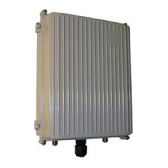
WAP-240 / WAP-500 Series There have one RJ45 connector and one N-type RF connector as standard packaging. The enclosure can be mounted to a wall using lag bolts or masonry screws. It can also be attached to a pole using the included pole clamps and U-bolts. -
Page 16: Rj45 Ethernet Connector System (Ecs)
RJ45 Ethernet Connector System (ECS) Assembly • Remove the thin enclosure nut from the feedthru assembly. This can be discarded. Loosen the compression nut completely. • Insert the RJ45 connector thru the feedthru assembly • Tighten the compression nut loosely •... - Page 17 RJ45 Field Installable Feedthru Connector Please follow up following instruction if your CAP / WAP comes with such connector which is lack of RJ45 ECS Installation Assembly • The RJ45 Field Installable Feedthru system is used to waterproof cable entries into outdoor enclosures to IP68 waterproofing standards.
-
Page 18: Power Over Ethernet Unit
Power over Ethernet Unit Plug the other end of the waterproof RJ-45 cable to the PoE device. The PoE device is guaranteed only in indoor environment. Caution: DON’T plug the power cord into PoE device before you finish install the antenna and Ground wire to ensure the safety. -
Page 19: Lighten Protector / Surge Protector
Lighten Protector / Surge Protector WAP / CAP come with built in lighten or surge protectors: WAP-240: • Surge protection for 2.4GHz antenna systems • Gas discharge tube design with multi-strike capability • Allows DC voltage to pass, suitable for tower-top electronics •... -
Page 20: Introduction
Pre-802.11n radio with software upgradeable to 802.11n, Pre- WiMAX radio (3.65GHz), and 802.11 a/b/g for WiFi hotspots. This highly flexible and scalable system is built to grow with the needs of any network. Like all WiBorne equipments, device is designed for easy installation and maintenance. - Page 21 The device is an outdoor NEMA rated box that houses a customized firmware. The router provides OSPF functionality on the routed ports that connect to two WiBorne Point to Point wireless backhaul radios which results in a layer 3 self-healing wireless networks.
-
Page 22: Getting Started
Getting Started It is always a good idea to first provision and test the equipment on the bench before deploying them in the field. This is a particularly useful exercise for the novice user. Management The device can be configured using a Command Line Interface (CLI) from HyperTerminal or console windows, Web Browser (HTTP) interface, or Winbox (GUI) interface. -
Page 23: Interfaces
Interfaces We have three levels of interface, Web based, Windows based, and command line interface through telnet or ssh remotely • Web Based Interface: This is a web based configuration interface for wireless firmware. Log in above to connect to this router - some of the most important firmware features can be controlled within this interface. -
Page 24: Primary Features And Pages Of The Browser Interface (Webbox)
The top left side of the configuration page offers a link to download the Winbox application. The application can also be downloaded from website or associated CD. Type the username (default: admin) and password (default wiborne [or blank if factory reset]) and continue. This will bring up the router’s Interface page (Webbox) You would see following menu for Quick Setup: By clicking Advanced, it then goes to next menu. - Page 25 Navigation Column: Each page features a navigation column that runs along the left- hand side of the page. On the bottom of the navigation column is the current status of the router including its System ID, IP address, Time, Date, CPU Utilization, Uptime, Disk Space Free, Disk Space Total, Memory Free, Memory Total, Rx, Tx, AP, Clients, and Timeout.
-
Page 26: Webfig (Web Browser) Interface
interface and check boxes of Protect customer, Protect router, and NAT. • Routes: This page will display all routing information with capabilities of adding static routes for each destination / netmask/gateway. • Simple Queues: Simple Queues (QoS) page allows you to rate limit traffic on the router. -
Page 27: Connecting To Wap/Cap
browser with JavaScript, of course). As WebFig is platform independent, it can be used to configure router directly from various mobile devices without need of software developed for specific platform. WebFig is designed as an alternative of Winbox as shown on below. Both have similar layouts and both have access to almost any feature of WAP/CAP. -
Page 28: Item Configuration
Menu bar has almost the same design as WinBox menu bar. Little arrow on the right side of the menu item indicates that this menu has several sub-menus. When clicking on such menu item, sub-menus will be listed and the arrow will be pointing down, indicating that sub-menus are listed. - Page 29 On the top you can see item type and item name. In example screenshot you can see that item is an interface with name bridge1 There are also item specific command buttons (Ok, Cancel, Apply, Remove and Torch). These can vary between different items. For example Torch is available only for interfaces.
-
Page 30: Skins
Skins Webfig skins is handy tool to make interface more user friendly. It is not a security tool. If user has sufficient rights it is possible to access hidden features by other means. Designing skins If user has sufficient permissions (group has policy edit permissions) Design Skin button becomes available. -
Page 31: Skin Example To Configure Wireless Interface->Status Page
Skin Example to Configure Wireless Interface->Status Page This is new functions from OS 5.7 that adds capability for users to create status page where fields from anywhere can be added and arranged. Status page can be created by users (with sufficient permissions) and fields on the page can be reordered. -
Page 32: Skin Design Examples
Two columns Fields in Status page can be arranged in two columns. Columns are filled from top to bottom. When you have only one column then first item intended for second should be dragged to the top of the first item when black line appear on top of the first item, then drag mouse to the left until shorter black line is displayed as showed in screenshot. -
Page 33: Using Skins
The result would be: Using skins To use skins you have to assign skin to group, when that is done users of that group will automatically use selected skin as their default when logging into WebFig. Note: WebFig is only configuration interface that can use skins If it is required to use created skin on other router you can copy files to skins folder on the other router. - Page 34 • An Ethernet (wired or wireless) connection between a PC and the device unit. • Ethernet PC connection to the device unit. You don’t need to define IP address of ethernet on the PC side. In order to use the Winbox simply connect the device unit to a PC and type the device’s IP address into the “Connect To”...
-
Page 35: Primary Features And Pages Of The Winbox Interface
Primary Features and Pages of the Winbox Interface Menu Bar: Winbox has a menu bar that runs along the left-hand side of the page. • Interface: General information of the interface, Status, Ethernet port settings and traffic. • Wireless: Wireless status, Access List, Registration, Connect List, Security Profiles, and wireless settings. -
Page 36: Command Line Interface
Types. • Drivers: Displays drivers for the Ethernet and Wireless chip set. • System: This button shows setting for Identity, Clock, Resources, License, Packages, Auto Upgrade, Logging, History, Console, Scripts, Scheduler, Watchdog, Reboot, Shutdown, NTP Client and NTP Server. • Files: Displays files on your router which include backups and hotspot html pages. -
Page 37: Telnet
Console cable. Telnet Open a command prompt (DOS) session on your PC. Open a Telnet session by typing: telnet [ip address of router] All device units are pre-configured at the factory. The factory default username is admin without password. Once you connect to the router you will be greeted with the current Firmware version information and prompted for a login. - Page 38 You can also use Windows native telnet program. Open and Windows console then type ‘telnet 10.1.1.201’: Or you can see following from HyperTeminal with 115200 8/N/1 xon/xoff: Another option is to use Winbox with ‘New Terminal’ option:...
-
Page 39: Console (Serial) Port
To terminate a CLI session (Telnet or Serial) type the command quit. Note: Type ? for a listing of CLI commands and directories. More basic information on the CLI will be covered throughout this text for advanced CLI commands by clicking “Manual”... -
Page 40: Management Serial Cable
Access of Console Port may be varied that is dependent on housing. Setting for HyperTerminal is: 115200 8/N/1 xon/xoff (for early version V2.9+, , use Flow Control to as ‘Hardware’) Management serial cable The console cable needs to be a 9 pin db female to 9 pin db female connector cable. A null modem cable can be used to manage the device unit. -
Page 41: Basic Configuration Through Web Browser
Basic Configuration through Web Browser This section describes a few basic concepts, as well as how to configure basic settings using the Browser (HTTP) Interface, or Webbox. This section is written to address only the most basic steps. It is highly recommended that you visit and read detailed manual to gain an understanding of all important configuration parameters. -
Page 42: Web Browser Interface Page
Web Browser Interface page Port Web Configuration Clicking on the IP address of the interface will bring up the port configuration page. The port can be disabled, configured to obtain an IP address from a DHCP server, or manually configured with an IP address and Netmask: Port Name Web Configuration Clicking on the name of the port will allow you to change the name of the port. -
Page 43: Interface Web Graphing
The ID of the device can also be changed from the system page. The unit can also be rebooted. The system page also provides you with a system RESET. Note: The system reset defaults the unit completely to system default configuration. You will then need to reload WiBorne’s default configuration. -
Page 44: Firewall Web Configuration
Firewall Web Configuration The device node by default is configured to use public interface ether 1 and NAT enabled. The web browser is the easiest way to create a firewall. Simply select a public interface and check the NAT box. Checking Protect Router and Protect Customer adds additional rules to strength the firewall. -
Page 45: Upgrading Firmware Through Web Browser
Upgrading Firmware through Web Browser The firmware can be upgraded from the web browser upgrade page. The firmware can be downloaded from our web site or original manufacture’s web site. Click on the UPGRADE from the navigation menu on the left side of the web page: A window browser will open for you to select the NPK file to upload. - Page 46 Once the file has been successfully uploaded to the router the upgrade and downgrade button can be used: The upgrade procedure will log out the current web session. The process will take a few minutes for the upgrade procedure to complete. Note: DO NOT POWER OFF router during this process To verify the upgrade procedure was successful.
-
Page 47: Remote Firmware Upgrade
Remote Firmware Upgrade WAP supports remote upgrade from Winbox, FTP, or EMS (Dude). A typical remote software upgrade can be done from Winbox->Systems->Auto Upgrade->Upgrade Package Sources. It can be done from Dude (EMS) as well:... - Page 48 Upgrading groups of routers You can define Groups of routers in the RouterOS --> Group. It is suggested to group routers that are in one network, because if you upgrade all your routers at one time, some of them might reboot while others are still downloading new files from Dude - this would interrupt the upgrade process for some devices because they could lose connectivity.
- Page 49 Then, you can upgrade many routers with one click:...
-
Page 50: Section 5 Basic Configuration Through Winbox
Section 5 Basic Configuration through Winbox This section describes how to configure basic settings using Winbox. This section is written to address only the basic steps. It is highly recommended that you study manual to gain an understanding of all important configuration parameters. In this section you will learn the following: •... -
Page 51: Configuring The Wireless Card
Configuring the Wireless Card Clicking the Wireless menu option from the menu bar will bring up the Wireless Tables. Double clicking on the wireless interface will bring up the Interface configuration menu. Once in the configuration menu there are a number of tabs General, Wireless, Data Rates, Advance and Status are just a few. - Page 52 The following tabs are presented in the firewall window: Filter Rules, NAT, Mangle, Connections, and Address Lists. Select the NAT table and click on the red plus sign to open the New NAT Rule window. Once the New NAT Rule window is open the Chain must be set to srcnat and the Out Interface.
-
Page 53: Configuring Dhcp Server
Configuring DHCP Server By default the DHCP Server service is enabled in WiBorne Broadband configuration on Ether1, 2, 3, 4, 5, WLAN, and the bridge interfaces. In order to create a DHCP Server from within Winbox select IP then DHCP Server. This will open the DHCP Server... - Page 54 Clicking the Setup button in the DHCP Server window will bring up the DHCP Server Setup window. Select the interface on which to run DHCP services. Once the interface is selected, the DHCP Address Space will need to be added. This will be followed by the Gateway for DHCP Network.
-
Page 55: Configuring Queues
Note: If not filled out properly the Setup will end without creating the DHCP server Lastly the Lease Time will need to be given. The default is 3 days. The format is days:hours:minutes:seconds. If this is filled out properly a success windows will open. Configuring Queues Introduction The bandwidth- manager is one of essential elements in a computer networks, which... -
Page 56: Packets Marking - Configuration
We will take up first way – the marking by user IP address. A few words about scripts: We would like to recommend using of scripts with a lot of entries generating, because the script makes it more comfortable. In order to use of scripts (winbox) one should choose 'System -> Scripts' from left menu. At follow up of report, the script made by internal scripts interpreter at the system will be marked as “(script)”. -
Page 57: New Queue Type Creating
address=(192.168.0. . $x ) action=mark-packet new-packet-mark=( $x . upload ) passthrough=no } This script marks movement from user, that is its upload. In order to change address class from 192.168.0 one should entry edit “src- address=(192.168.0.)”. It is very important to put full stops at the same place as at above example. -
Page 58: The Main Queue Creating
(terminal) /queue type add name="sfq" kind=sfq sfq-perturb=5 sfq-allot=1514 The element above has decided about the algorithm, which enables bandwidth division process at range of one group/ category. The main queue creating The process of clearly forming movement occure at the main queue, which are consistent with htb on algorithm rule. -
Page 59: Optimization
The script will generate 254 queues. Each of those will be limiting the download for single mark (IP address), guaranteeing it the 32Kbps bandwidth and limiting to 256Kbps. The guarantee would be consisted in accounting two virtually queues: first, the limit-at counting (guaranteed speed), and the second one, max-limit (maximal speed), taking into consideration that limit-at queue will proceed through separate and higher prioritised path for the moment of limit-at value exceeding. -
Page 60: Per Connection Queue (Pcq) Examples
We might remove the ICMP movement from the mark. It is very useful when we want to provide good PINGs, regardless of exploit degree for link and individula queues of users. In this case, one have to add following (terminal) at the beginnig (before others rules at/IP firewall mangle): (terminal) /ip firewall mangle add chain=prerouting protocol=icmp action=accept... - Page 61 Next, Mark all packets with packet-mark all. create Mangle: IP->Firewall->Mangle: /ip firewall mangle add chain=prerouting action=mark-packet new-packet-mark=all passthrough=no...
- Page 62 Now Setup two PCQ queue types - one for download and one for upload. dst-address is classifier for user's download traffic, src-address for upload traffic: /queue type add name="PCQ_download" kind=pcq pcq-rate=64000 pcq-classifier=dst-...
- Page 63 address /queue type add name="PCQ_upload" kind=pcq pcq-rate=32000 pcq-classifier=src- address...
- Page 64 Finally, two queue rules are required, one for download and one for upload: /queue tree add parent=global-in queue=PCQ_download packet-mark=all...
- Page 65 /queue tree add parent=global-out queue=PCQ_upload packet-mark=all Now you can turn bandwidth tool by using Tools->Bandwidth Test:...
-
Page 66: Alignment Tool
Alignment Tool It provides an "antenna alignment tool" that shows you a moving bar representing the received power. When the bar is at the maximum, the antenna is aligned. With some routers, you can also enable an audio feedback mode. This causes the router to emit a loud tone, changing the pitch according to the received power. - Page 67 wlan1: From Interface (wlan1), choose Wireless tab, and choose frequency that you want to scan, then click “Scan…” button: Click Start to scan wireless network. Now choose the wireless node that you are going to perform alignment with: We will use Mac address of selected node for alignment utility with current WAP/CAP.Double click selected node (SSID is ‘master’...
- Page 68 Back to Scan window, now click ‘Connect’ button: We will now use the obtained MAC address in the Alignment utility. Once this is done, you should hear your WAP/CAP’s speaker start beeping and as you start to move the antenna around, the beep should vary in delay or increase according to the signal strength of your link.
- Page 69 Now click Start: You should hear current WAP/CAP is beeping according to strength of link, and aligned far side of WAP/CAP (“master”) here is shown: Alignment Tool with other branding Devices When you got to the remote site, you set the MAC address of the opposite (non- WAP/CAP) end of the connection into the alignment settings and turned the alignment feature on.
-
Page 70: Method 2: Alignment-Only Mode
Now click Align button then you would see signal strength of associated node: Method 2: Alignment-Only Mode alignment-only - Put interface in a continuous transmit mode that is used for aiming remote antenna. Once you have configure Settings in Align tab, you can switch to ‘alignment only’ mode and beep would be varied based on strength of link. -
Page 71: Method 3: Cli Command
Method 3: CLI command: You can also enter this command, Set mode=alignment-only and specify, audio-monitor (MAC address; default: 00:00:00:00:00:00) - MAC address of the remote host which will be 'listened' ssid-all=yes Then run 'interface wireless align monitor'. The interface will automatically go into the alignment-only mode. however. You may have always had to set the mode on both sides for the audio to work right! Audio and Video (LED) Aiming Script Scripts for audio / video (LED) aiming purpose is available. - Page 72 # >= Level 8 : 4 solid (100ms beeps) # >= Level 7 : 3 solid, 4th flashing (300ms beeps) # >= Level 6 : 3 solid (500ms beep cycle) # >= Level 5 : 2 solid, 3rd flashing (700ms beeps) # >= Level 4 : 2 solid (900ms beeps) # >= Level 3 : 1 solid, 2nd flashing (1100ms beeps) # >= Level 2 : 1 solid (1300ms beeps)
- Page 73 :local lnslevel4 50; :local lnslevel3 45; :local lnslevel2 40; :local lnslevel1 35; # The (very approximate) running time of the script # is set here. :local lnsrunningtime 60m; # Here, we set how long the script will beep. NOTE that # startup/shutdown tones will still be played.
- Page 74 :set lnsdelaytime 500ms; :led user-led=yes led4=no led3=yes led2=yes led1=yes; :if ($lnsrunningtime > $lnsrunbeepdiff) do={ :beep frequency=$lnsbeepfreq length=($lnsdelaytime / 2); :delay $lnsdelaytime; :if ($"signal-to-noise" >= $lnslevel5 && $"signal-to-noise" < $lnslevel6) do={ :set lnsdelaytime 700ms; :if ($lnsrunningtime > $lnsrunbeepdiff) do={ :beep frequency=$lnsbeepfreq length=($lnsdelaytime / 2); :for i from=1 to=3 do={ :led user-led=yes led4=no led3=no led2=yes led1=yes;...
- Page 75 :delay ($lnsdelaytime / 6); :if ($"signal-to-noise" < $lnslevel1) do={ :set lnsdelaytime 1700ms; :if ($lnsrunningtime > $lnsrunbeepdiff) do={ :beep frequency=$lnsbeepfreq length=($lnsdelaytime / 2); :led user-led=yes led4=no led3=no led2=no led1=no; :delay $lnsdelaytime; } else={ :if ($"status" = "searching-for-network") do={ :set lnsdelaytime 2000ms; :led user-led=no led4=no led3=no led2=no led1=no;...
-
Page 76: Power / Nand / User Led
# shut off LEDs, play shutdown tones :delay 50ms; :led user-led=no led4=no led3=no led2=no led1=no; :delay 50ms; :beep frequency=($lnsbeepfreq - 200) length=50ms; :delay 50ms; :beep frequency=($lnsbeepfreq - 300) length=50ms; :delay 50ms; Power / NAND / User LED Power LED Power LED (blue) is on when the board is powered. NAND LED (Green) for disk activity. User LED User LED may be programmed at user's option. -
Page 77: Audio-Only Aiming Script
Audio-only Aiming Script # 10 sec delay required by ROS3 for startup scripts? :delay 10 # set the interface you want to monitor :local interface "wlan1"; #set the sound frequency you want to use (in Hz) :local beepfreq "523.251"; #set the number of iterations - approx 1-2 seconds per iteration :local iterations "150";... - Page 78 :local s50 "10ms"; :for i from=1 to=$iterations do={ /interface wireless monitor $interface once do={ :if ($"signal-strength" <= -90) do={ :delay $no; :if ($"signal-strength" -90) do={ :for i from=1 to=2 do={ :beep length=$beep frequency=$beepfreq; :delay $s90; } :if ($"signal-strength" -85) do={ :for i from=1 to=3 do={ :beep length=$beep frequency=$beepfreq;...
-
Page 79: The Eoip Bridge
The EoIP Bridge Introduction There are some kind of movement which has to be separated from another one, which move on the already existing logical link. One of the most simply method of gaining satisfied separation is to create parallel virtual link – tunnel. The tunnel enables data transmission and depending on the kind of tunnel, we may additionally profit by that- for example, data encryption, packets compression. - Page 80 Now, we have already been creating the wireless interface configuration. At the beginnig you have to turn the wireless card ON (cause it is OFF in the default settings) by clicking on the icon of given card with right mouse button and choose the „enable” option. Change the card settngs to 'ap bridge' work mode, select the proper frequency, channel and entry „ssid”.
- Page 81 We have been creating the EoIP tunnel at this moment. In order to do it, choose „+” from interface list and then „EoIP Tunnel” from avilable interfaces list.
- Page 82 This time we have to assign the IP address of wireless interface, placed in client unit, and the ID Tunnel identificator (the same for both side). It is worth to remember that it might appear two identical MAC addresses in the network. Additionally, if one would like to use many tunnels for single device, one should remember that every tunnel have to have the diffrent ID Tunnel parameter.
-
Page 83: The Client Unit Configuration
Next at the „Ports” tab, where in the already bridge created, one should add the EoIP and Ethernet ports by clicking „+”. After the ports adding the window should look like following picture: The client unit configuration Before the configuration beginning, one should reset the device to factory presets (the console command: /system reset –... - Page 84 We have started the wireless interface configuration. Firstly, one should turn the wireless card ON (cause it is OFF in default settings) by clicking on the given card icon with right mouse button and choosing the “enable” option. Set the card to „station” work mode, choose the properly frequency, channel and then enter „ssid”.
- Page 85 The EoIP tunnel creating. Choose „+” at the interface list and then „EoIP Tunnel” from available inteface list.
- Page 86 This time we have to assign the IP address of wireless interface, placed in client unit, and the ID Tunnel identificator, as the same as the previous time,however one have to change the MAC address for another one. The Bridge creating. The Ethernet port and the EoIP Tunnel have been added to the bridge by.
-
Page 87: The Wds Bridge
Now, between the Ethernet interface of two devices the communication should be run, what is pictured below: The WDS Bridge Creating the transparent bridge is one of main assumptions of our configuration. In order to make it the system will be moving data from one interface to another one with the bridge. - Page 88 After logging onto device with the Winbox (more description in guide „first logging on”) firstly we have to create the bridge. Choose „Bridge” from the main menu (on the left) and then click on „+” from already appeared 'Bridge submenu' and „OK”. Next, in the 'Port' tab we have been configuring the interfaces belonged to the bridge.
- Page 89 on „+” and our gateway is added. Creating wireless link. The first card will be presented in the 'ap bridge' mode. We may test the ether as regard of prescence other networks with using of the snooper. It will be helpful at choice of work channnel. Firstly find the free frequency and choose that.
- Page 90 It is worth to protect the access to WAP-520 by ticking off „default authenticate”. Only added MAC address (from wireless card of WAP-520) would be connected at this moment. We have to add it at 'wireless' tab, where we should add the address to the fields od 'Access list' and to the connect list.
- Page 91 At the 'Nstreme' tab set, as below: If one use the routerboard and would like to uprate at maximal degree, then one should turn off the 'connection tracking'. In order to do it choose the 'IP' -> Firewall -> 'Connections' tab -> click on „tracking” button.
-
Page 92: Output Support File (Supout.rif)
Please remember to configure all cards according to this mini instruction. Please not forget about adding MAC addresses to the Access and Connect list. Output Support File (supout.rif) 'The support file is used for debugging WAP/CAP and to solve the support questions faster. -
Page 93: Upgrading Firmware Through Winbox
Then drag such supout.rif to Windows Explorer and send to Support Team. You can also use Winbox->Make Supout.rif shown on left menu bar of above snapshot, then go to File to drag & drop supout.rif and send it out for support. Of course, it is also possible to download the file with FTP/SFTP or to automate this process with scripting, and have the file emailed to you. - Page 94 Below window then pop up for sending firmware files: Once above window closed itself, you will see File List from Winbox that indicated these two files are transferred:...
- Page 95 3. Now from Terminal window, type /system reboot It may take up to 30 seconds or more to finish rebooting. 4. Upgrade BIOS. Once system is booted back, open Winbox->Terminal, type below commands: /system routerboard print /system routerboard upgrade /system reboot This will update your bios from 2.41 onto 3.02, you are done.
- Page 96 configuration will be the same as original.
-
Page 97: Basic Configuration Through Cli
Basic Configuration through CLI This section describes a Command Line Interface configuration. This section is written to address only the basic steps. It is highly recommended that you visit and read Manual to gain an understanding of all configuration parameters. In this section you will learn the following: •... -
Page 98: Configuring Gateway Through Cli Setup
Configuring Gateway through CLI Setup Simply selecting an option will bring the next menu prompt. The only information needed to set the Gateway is the gateway IP address. Example of configuring the Gateway on the router... -
Page 99: Configuring Dhcp Client Through Cli Setup
Configuring DHCP Client through CLI Setup Follow the menu options and supply the interface which is to be configured as a DHCP client. Configuring DHCP Server through CLI Setup Following the menu option the following information will need to be provided in order to create the DHCP Server •... -
Page 101: Sample Default Configuration
Sample Default Configuration Following is sample default configuration for device. Actual default configuration is saved with backup file (factory.backup). The device node is configured with the wired ports (EtherN) as router ports, each with their own IP address. The ports are also configured to give out DHCP IP addresses. -
Page 102: Restoring Default Configuration From Winbox
Restoring Default Configuration from WinBox Each router has a backup of this configuration stored in its file system. The backup file can be seen through Winbox by selecting files. The name of the backup file is “factory.backup”. Select this file and click on Restore and the unit will prompt you to restore and reboot. -
Page 103: Restoring Default Configuration From Cli
or visa versa, copy Windows files to Clipboard and paste it onto devices Restoring Default Configuration from CLI The default configuration can also be reloaded through the command line. Simply login to the devices and type the following command: /system backup load name=factory.backup You can save your backup with CLI: /system backup save name=mybackup... -
Page 104: Settings For Wireless Access Point & Clients
Settings for Wireless Access Point & Clients Here we illustrate some simple examples for deployment of P2MP or P2P. Wireless Station Modes Overview Wireless interface in any of station modes will search for acceptable access point (AP) and connect to it. The connection between station and AP will behave in slightly different way depending on type of station mode used, so correct mode must be chosen for given application and equipment. -
Page 105: Applicability Matrix
• destination address - address of station device, also radio receiver address • radio transmitter address - address of AP • source address - address of originator of particular frame Frame transmitted from station to AP has the following addresses: •... -
Page 106: Mode Station
station-wds station-pseudobridge station-pseudobridge- clone station-bridge Mode station This is standard mode that does not support L2 bridging on station - attempts to put wireless interface in bridge will not produce expected results. On the other hand this mode can be considered the most efficient and therefore should be used if L2 bridging on station is not necessary - as in case of routed or MPLS switched network. -
Page 107: Mode Station-Pseudobridge-Clone
received from AP. IPv4-to-MAC mappings are built also for VLAN encapsulated frames. • single MAC address translation for the rest of protocols - station learns source MAC address from first forwarded non-IPv4 frame and uses it as default for reverse translation - this MAC address is used to replace destination MAC address for frames received from AP if IPv4-to-MAC mapping can not be performed (e.g. - Page 108 On Access Point: • mode=ap-bridge • frequency=2142 • band=2.4GHz-B/G • ssid=WAP • disabled=no On client (station): • mode=station • band=2.4GHz-B/G • ssid=WAP • disabled=no Bring up winbox.exe and search connected WAP/CAP nodes by clicking highlighted widget then click Connect widget: Configuration for Access Point (WAP) Select Wireless and double click wlan1...
- Page 109 Choose Wireless from pull-down widget: Set Mode, SSID, Band, and Frequency, then click OK.
- Page 110 Now assign IP address: Click Add button: Assign IP, Network, and Broadcast, and choose Interface to be wlan1, click Ok.
- Page 111 Leave rest as default options and You are done for setting of AP mode Configuration for Station (CAP) Set Mode, SSID, Band, and Frequency, then click OK. Assign IP, Network, and Broadcast, and choose Interface to be wlan1, click Ok...
-
Page 112: Ap Bridge / Station Pseudo-Bridge
Check whether you can ping the Access Point from Station: Tools->Ping AP Bridge / Station Pseudo-bridge Single Radio on One WAP You have one radio on each side of WAP or CAP, and use such radio as backhaul to create bridging (transparent) mode of wireless LAN network. You can bridge WAP and CAP such that all clients IP addresses are transparent that can reach each other. -
Page 113: Configuration For Access Point (Wap)
Once configuration is done, you would be able to ping between 10.1.1.101 and 10.1.1.201 Configuration for Access Point (WAP) Create a bridge1 to bridge ether1 and wlan1 by using default parameters: Double click bridge1: You can take all default parameter for bridge1. To add Ports onto Bridge. - Page 114 Setup wireless information for wlan1: You must hit Apply or Ok to save change. Note that SSID string shows blue which means that you already made change but not been saved yet. You can keep rest as default. Define IP address of either1 to be 10.1.1.100: IP->Address then click “+” sign to add address:...
- Page 115 You can key in 10.1.1.100/24 for single subnet: Once hit Apply, it would assign Network and Broadcast automatically: Back to Interfaces, you should see following available interface List:...
- Page 116 “R” shows such interface is running. It is ok if you don’t see “R” shown on wlan, which means no association from wireless client, is available. Configuration for Station (CAP) If you don’t use any CAP for Client CPE, you can ignore following. Create a bridge1 to bridge ether1 and wlan1 by using default parameters: Add interface (either1 and wlan1) onto ports of bridge...
- Page 117 Now you should see bridge1 that bridges both ether1 and wlan1 together: Configuring wlan1: Wireless->wlan1. Choose Station pseudobridge Mode. You can use Scan function to scan corresponding AP. Hit Apply.
-
Page 118: Dual Radios On One Wap
Define IP address of bridge1: IP->Addresses, choose “+” if IP address of ether1 is not defined yet: Now you should be able to ping between two PCs (10.1.1.101 and 10.1.1.201) Additional reference: WAP-520_CAP-500_UG.pdf Dual Radios on One WAP You have two radios on each side of WAP or CAP, and use one of radios, say, 5 GHz frequency of radio, to act as backhaul connection between two sites. -
Page 119: Configuration For The 1 St Access Point (Wap)
Here shows bridging transparent mode that communicates two sites onto single LAN. You can bridge WAP and CAP such that all clients IP addresses are transparent that can reach each other. This usually applies to WiFi or VoIP for billing systems. To solve this problem, the ap-bridge and station pseudo-bridge mode was created - it works just like a station, but connects to APs without additional routing. - Page 120 You can take all default parameter for bridge1. To add Ports onto Bridge, make sure ether1, wlan1, and wlan2 are added shown here: Setting wlan1: 2.4 GHz Now Choose Wireless->wlan1 You would not see wlan2 if you only have one wireless radio available. If you see above wlan2 is grayed out, you can click check mark √...
- Page 121 Setup wireless information for wlan1: You must hit Apply or Ok to save change. Note that SSID string shows blue which means that you already made change but not been saved yet. You can keep rest as default. Setting wlan2: 5 GHz Similar with 2.4GHz, you can define wireless parameter:...
- Page 122 Nstreme model – optional If you plan to have higher throughput then you can enable Nstreme protocol on both WAP and CAP backhaul. You must enable it on both side such that microwave can go through. See also next Chapter for “Configuring Nstreme”.
- Page 123 Ack Timeout For long range greater than 10KM, you would need to adjust Ack Timing for best performance: Interface->wlan2->Wireless, then choose Advanced Mode: Choose Advanced tab:...
- Page 124 Here you can use Scan function to find associated client, and adjust Ack Timeout:...
- Page 125 Refer to Appendix B: Setting for Ack Timeout. Note: • Under nstreme it is not necessary to set ack timeout. Just leave it as dynamic. • ack-timeout must be set to same value for both end of WAPs. To improve performance, you can turn off Tracking from Firewall: IP->Firewall- >Connection:...
- Page 126 Uncheck Enabled, hit Apply: Define IP address of either1 to be 10.1.1.100: IP->Address then click “+” sign to add address:...
- Page 127 You can key in 10.1.1.100/24 for single subnet: Once hit Apply, it would assign Network and Broadcast automatically: Back to Interfaces, you should see following available interface List: “R” shows such interface is running. It is ok if you don’t see “R” shown on wlan, which means no association from client(s) is available.
-
Page 128: Nd Access Point (Wap)
Configuration for the 2 Access Point (WAP) Bridge: same configuration with the 1 2.4GHz: same configuration with the 1 5 GHz: choose station pseudobridge mode: IP address of ether1: same with the 1 WAP, but use 10.1.1.200/24 instead. L2 Transparently Bridge (WDS-Bridge, or station-wds Mode) Remote networks can be easily bridged using L2 WDS-bridging feature of WAP or CAP. -
Page 129: Ap Side (Com)
Let us configure Master Link (COM and CPEM), here COM means ODU with AP mode, while CPEM means ODU with Station (or Client) mode. Follow the steps below to create transparent bridge using WDS: AP Side (COM) First, reset what you have done: /system reset Reboot, # set ID... - Page 130 Once click Apply: Then click Ports and add ether1 onto bridge1:...
-
Page 131: Station Side (Cpem)
or in console /interface bridge add name=bridge1 /interface bridge port add interface=ether1 bridge=bridge1 You do not need to bridge WLAN1 at this moment. Station side (CPEM) Do the same on the Station (CPEM), and add ether1 and wlan1 interfaces to the bridge in Winbox or in console /int bridge add name=bridge1... - Page 132 2. Make sure you have communication between WAP routers, i.e., one router is configured as server (AP, or COM), the other one as client (station, or CPEM). Configure wireless interface wlan1 on AP in WinBox or in conslole /interface wireless set wlan1 disabled=no ssid=master frequency=5825 band=5ghz-a \ mode=bridge channel-width=40mhz scan-list=5825-5875 wireless-protocol=nstreme \ frequency-mode=superchannel dfs-mode=none country=india /int wireless nstreme set wlan1 enable-nstreme=yes disable-csma=yes \...
- Page 133 or in console /interface wireless set wlan1 disabled=no ssid=master frequency=5825 band=5ghz-a \ mode=station-wds channel-width=40mhz scan-list=5825-5875 \ wireless-protocol=nstreme frequency-mode=superchannel dfs-mode=none country=india /int wireless nstreme set wlan1 enable-nstreme=yes disable-csma=yes \ framer-policy=best-fit framer-limit=3200 3. Create wds interface on AP (COM) and add the interface to the bridge in WinBox...
- Page 134 or in console /interface wireless set wlan1 wds-mode=dynamic wds-default-bridge=bridge1 4. Check whether the WDS link (on COM side) is established in WinBox or in console [admin@COM] > /int wireless wds print Flags: X - disabled, R - running, D - dynamic 0 RD name="wds1"...
- Page 135 or in COM console /ip address add address=10.1.1.31/24 broadcast=10.1.1.255 interface=bridge1 And in CPEM conole: /ip address add address=10.1.1.32/24 broadcast=10.1.1.255 interface=bridge1 # disable firewall tracking for better performance for both AP COM and Client CPEM: /ip firewall connection tracking set enabled=no 5.
-
Page 136: Full Scripts
Full Scripts #----------------------------------------------------------------------- # Transparently Bridge two Networks for P2P # based on V4.14 #----------------------------------------------------------------------- #----------------------------------------------------------------------- # COM ODU (AP) #----------------------------------------------------------------------- # uncommon this line to reset system, prior of running following script #/system reset # change password #/ password # set ID /system identity set name=COM # create bridge for ether1 (later for wlan1) - Page 137 /interface wireless set wlan1 disabled=no ssid=master frequency=5825 band=5ghz-a \ mode=bridge channel-width=40mhz scan-list=5825-5875 wireless-protocol=nstreme \ frequency-mode=superchannel dfs-mode=none country=india # enable nstreme propritary /int wireless nstreme set wlan1 enable-nstreme=yes disable-csma=yes \ framer-policy=best-fit framer-limit=3200 #Create wds interface for wlan1 and add the interface to the bridge /interface wireless set wlan1 wds-mode=dynamic wds-default-bridge=bridge1 #add ip address /ip address add address=10.1.1.31/24 broadcast=10.1.1.255 interface=bridge1...
-
Page 138: Pre-Configured .Rsc File
/ip address add address=10.1.1.32/24 broadcast=10.1.1.255 interface=bridge1 # disable firewall tracking for better performance /ip firewall connection tracking set enabled=no # backup as 'factory' /system backup save name=factory Pre-configured .rsc file If you need help to setup a script that will reset a customers CPE and then run a edited custom script with SSID of AP + NV2,etc setting to re-associate with AP, you can do this: Create your configuration script: /int wirel set wlanX ssid=blabla... - Page 139 ############# # 1. Edit the file below. # 2. Replace all instances of 230.60 with 230.x , x being the new IP allocated for this unit. Use the Edit>>Replace Function (Ctrl H) # 3. Replace all instances of 253.60 with 253.x # 4.
- Page 140 /system logging action set 0 memory-lines=100 memory-stop-on-full=no name=memory target=memory set 1 disk-file-count=3 disk-file-name=log disk-lines-per-file=300 \ disk-stop-on-full=no name=disk target=disk set 2 name=echo remember=yes target=echo set 3 bsd-syslog=no name=remote remote-port=514 src-address=0.0.0.0 \ syslog-facility=daemon syslog-severity=auto target=remote /system logging set 0 action=disk disabled=no prefix="" topics=info set 1 action=disk disabled=no prefix=""...
-
Page 141: Firewall
Firewall Security Information sources ENISA – http://www.enisa.europa.eu/ OWASP http://owasp.org Rits Group – http://www.ritsgroup.com/ ISAS – http://www.isas.ie/ SANS Institute – http://sans.org CIS Centre for Internet Security – http://cisecurity.org/ NIST Computer Security http://csrc.nist.gov/ Open BSD – http://OpenBSD.org/ Spamhaus.org – http://spamhaus.org nmap.org – http://nmap.org ha.ckers.org –... - Page 142 All commands can be prefaced with an absolute or relative reference to the context in which the command is to be executed. If no context is given, the current context is used. Below three examples: [admin@WAP] /ip address> print This "print" command will be executed in the "/ip address" context, and will therefore print all configured IP addresses.
-
Page 143: Basic Commands
Basic commands The same basic commands are used to configure all aspects of the OS. Commands exist to look at configuration, to add configuration, to remove configuration, and to edit existing configuration. print The "print" command prints configuration items in the current context. It has several qualifiers that can be used to change what information is output, and how it is formatted. -
Page 144: Set
1.1.1.2/29 1.1.1.0 1.1.1.7 outside 10.2.0.1/24 10.2.0.0 10.2.0.255 [admin@WAP] > /ip address remove 2 [admin@WAP] > /ip address print Flags: X - disabled, I - invalid, D - dynamic ADDRESS NETWORK BROADCAST INTERFACE 10.1.0.1/24 10.1.0.0 10.1.0.255 inside 1.1.1.2/29 1.1.1.0 1.1.1.7 outside [admin@WAP] >... -
Page 145: Disable
1.1.1.2/29 1.1.1.0 1.1.1.7 outside 10.2.0.1/24 10.2.0.0 10.2.0.255 inside [admin@WAP] > /ip address set 2 interface=dmz [admin@WAP] > /ip address print Flags: X - disabled, I - invalid, D - dynamic ADDRESS NETWORK BROADCAST INTERFACE 10.1.0.1/24 10.1.0.0 10.1.0.255 inside 1.1.1.2/29 1.1.1.0 1.1.1.7 outside 10.2.0.1/24... -
Page 146: Find
ADDRESS NETWORK BROADCAST INTERFACE 10.1.0.1/24 10.1.0.0 10.1.0.255 inside 1.1.1.2/29 1.1.1.0 1.1.1.7 outside 10.2.0.1/24 10.2.0.0 10.2.0.255 [admin@WAP] > find The "find" command returns a set of items that can then be acted on by other commands. When "find" is executed without any parameters, it returns all items. When "find" is executed with parameters only items that match the parameters are returned. -
Page 147: Move
10.1.0.1/24 10.1.0.0 10.1.0.255 inside 1.1.1.2/29 1.1.1.0 1.1.1.7 outside 2 X 10.2.0.1/24 10.2.0.0 10.2.0.255 [admin@WAP] > The below enables all IP addresses that are on interfaces that start with the letter "d": [admin@WAP] > /ip address print Flags: X - disabled, I - invalid, D - dynamic ADDRESS NETWORK BROADCAST... -
Page 148: Context
Context Contexts can also be set for a set of commands by enclosing a set in braces, saving keystrokes. The below enables all IP addresses: [admin@WAP] > /ip address print Flags: X - disabled, I - invalid, D - dynamic ADDRESS NETWORK BROADCAST... -
Page 149: Router Interfaces (Ports)
Router interfaces (ports) Physical interfaces Different router models have different sets of physical interfaces. RB1000s have a total of 4 1000Base-TX ports. RB1100s have 10 1000Base-TX ports (2 groups of 5 ports with a 1Gbps pipe to the CPU per group, each group has a switch chip for wire speed layer 2 throughput), and 3 100Base-TX ports. -
Page 150: Bridging Vs Routing
set [find name=ether5] master-port=ether2 The switch chip is capable for small networks, but can't do advanced VLAN configurations. Bridging vs routing Bridging (which is what switches do) is something that switches do a lot better than routers. This is just a personal opinion, but whenever I find myself thinking that I should bridge wired interfaces I almost always end up using a switch instead. -
Page 151: Dhcp Client
10.1.0.1/24 10.1.0.0 10.1.0.255 inside [admin@WAP] /ip address> add address=1.1.1.2/29 interface=outside [admin@WAP] /ip address> print Flags: X - disabled, I - invalid, D - dynamic ADDRESS NETWORK BROADCAST INTERFACE 10.1.0.1/24 10.1.0.0 10.1.0.255 inside 1.1.1.2/29 1.1.1.0 1.1.1.7 outside [admin@WAP] /ip address> DHCP client In many small environments the router will receive a dynamic IP address via DHCP on its WAN interface from the ISP. -
Page 152: Ip Routes
IP routes Just like on other routing platforms dynamic connected routes are created for all networks that the router has IP addresses to - after all, if the router has an IP address in the 10.1.0.1/24 network on the "inside" interface then it can reach hosts on that network via that interface. -
Page 153: Example Network
be used when the public IP address on the WAN interface is also static. Example network In our example network we want the router to use 1.1.1.1 as a default gateway: /ip route add dst-address=0.0.0.0/0 gateway=1.1.1.1 DHCP server DHCP server services consist of three components: the IP pool that defines the range of IP addresses clients can receive a lease for, the DHCP server network that defines the parameters clients are passed (such as gateway IP address and DNS servers), and the DHCP server instance itself that ties a pool to an interface. -
Page 154: Dhcp Servers
The minimum set of options include the default gateway and name servers. The default gateway is usually the IP address of the router on the network interface, and the name servers usually is as well - at least as long as the router is configured as a DNS caching resolver. -
Page 155: Lease Time Considerations
Flags: X - disabled, I - invalid NAME INTERFACE RELAY ADDRESS-POOL LEASE-TIME ADD-ARP DHCP-... inside DHCP-Pool-Ins... 3h [admin@WAP] /ip dhcp-server> set [find interface=inside] lease-time=1h [admin@WAP] /ip dhcp-server> print Flags: X - disabled, I - invalid NAME INTERFACE RELAY ADDRESS-POOL LEASE-TIME ADD-ARP DHCP-... -
Page 156: Ip Firewall
add address-pool=DHCP-Pool-inside authoritative=yes bootp-support=static \ disabled=no interface=inside lease-time=3h name=DHCP-inside IP firewall The IP firewall is responsible for filtering packets (accepting or dropping them), as well as changing their properties. Three facilities exist: filter, mangle, and NAT. Only filter and NAT are discussed here. Filters Filters are used to drop or accept packets going through the router or going to the router. -
Page 157: State
'postrouting' chain. Though somewhat complicated, realistically only two chains are important for simple SoHo routers: the router itself is secured in the 'input' chain, and the hosts on networks behind the router are secured in the 'forward' chain. To learn about all the details of chains and how packets move through the firewall refer to the single best page on the wiki: the Packet Flow page. -
Page 158: Nat
add chain=input connection-state=invalid action=drop add chain=input in-interface=inside action=accept add chain=input action=drop First all packets in established and related connections are permitted. Then all invalid packets are dropped. Then packets coming in via the 'inside' interface are permitted - this allows hosts on the 'inside' network to establish connections to the router. Finally any packets that don't match those rules are dropped. -
Page 159: Source Nat
the packet gets to the web server and the server replies it sends the packet with a source IP address of 5.5.5.5 and a destination IP address of 1.1.1.2. Once the packet gets to the router it is found to be part of an existing connection, and that the original source address was 10.1.0.10. -
Page 160: Example Network
Unlike source NAT all destination NAT is static. Destination NAT is often used for port forwarding to allow Internet resources to access devices on the local network. It is possible to forward all IP traffic, or just specific ports for specific protocols. It is important to be very specific when writing destination NAT rules: for example, it is easily possible to forget to specify a destination IP address and to just apply destination NAT to all HTTP and HTTPS traffic. - Page 161 /ip firewall filter Deny any one who is on the ssh_blacklist a new session on any protocol. add chain=input protocol=tcp dst-port=22 src-address-list=ssh_blacklist action=drop \ comment="drop ssh brute forcers" disabled=no Allow anyone who was on the "ssh_stage3" to connect a new session on port 22 and add the address to the "ssh_blacklist "...
-
Page 162: Dos Attack Protection
comment="drop ssh brute downstream" disabled=no DoS attack protection Diagnose Are there too many connections with syn-sent state present? /ip firewall connection print Are there too many packets per second going through any interface? /interface monitor-traffic ether3 Is CPU usage 100%? /system resource monitor Are there too many suspicious connections? /tool torch... -
Page 163: Syn Cookies
action=drop comment="" disabled=no 'syn limit=400' is a threshold, just enable rule in forward chain for syn packets to get dropped (for excessive amount of new connections) SYN cookies /ip firewall connection tracking set tcp-syncookie=yes Setup firewall rules to protect your router First thing is to set address list of IP’s that include the local network and static IP addresses for remote access to the router in case need to setup something for the client. -
Page 164: Add Users To The System
Or, type the following command in the CLI: [admin@WAP] > / password old password: new password: ****** retype new password: ****** This will change your current admin's password to what you have entered twice. Make sure you remember the password! If you forget it, there is no recovery. You need to reinstall the router! Add users to the system You should add each user that is going to log on to the router as a separate user and... -
Page 165: Setup Mac Filtering (Mac Locking)
All packets with destination to the router are processed against the ip firewall filter's input chain. Note, that the input chain does not affect packets which are being transferred through the router! You can add following rules to the input chain under /ip firewall filter (just 'copy and paste' to the router using Terminal Console or configure the relevant arguments in WinBox): / ip firewall filter... -
Page 166: Connections Tracking
/ip firewall filter add chain=forward src-mac-address=aa:bb:cc:dd:ee:ff action=drop IP --> DHCP Server --> Leases --> Add new --> General="Pool_Name", MAC Address="MAC address of desired blocked", Server="Name of DHCP Server failing", Block access = yes, Address List = Black-list Connections Tracking You can disable or enable connection tracking. Disabling connection tracking will cause several firewall features to stop working. -
Page 167: Basic Universal Firewall Script
Basic universal firewall script This is a basic firewall that can be applied to any Router. This script has basic rules to protect your router and avoid some unnecessary forwarding traffic. Pay attention for all comments before apply each DROP rules. First we need to create our ADDRESS LIST with all IPs we will use most times Below you need to change x.x.x.x/x for your technical subnet. - Page 168 add address=224.0.0.0/4 comment="MC, Class D, IANA # Check if you need this subnet before enable it"\ disabled=yes list=bogons Now we have protection against: SynFlood, ICMP Flood, Port Scan, Email Spam and much more. For more information read the comments. /ip firewall filter add action=add-src-to-address-list address-list=Syn_Flooder address-list-timeout=30m chain=input \ comment="Add Syn Flood IP to the list"...
-
Page 169: Minimum Firewall Rules
Minimum Firewall Rules Below are minimum Firewall Rules to prevent our network from hacker attack. /ip firewall filter add action=drop chain=input comment="" disabled=no dst-port=20-21 protocol=\ tcp src-address-list=!allow add action=drop chain=input comment="" disabled=no dst-port=22 protocol=tcp \ src-address-list=!allow add action=drop chain=input comment="" disabled=no dst-port=23 protocol=tcp \ src-address-list=!allow add action=drop chain=input comment=""... - Page 170 To deny access to router to the router via Telnet (TCP port 23) /ip firewall filter add chain=input protocol=tcp dst-port=23 action=drop Chain Forward Protecting the customers from viruses and protecting the Internet from the customers. Block IP addreses called "bogons": add chain=forward src-address=0.0.0.0/8 action=drop add chain=forward dst-address=0.0.0.0/8 action=drop add chain=forward src-address=127.0.0.0/8 action=drop...
- Page 171 a NAT router replace the private source address of an IP packet with anew public IP Address as it travel trough the router. • which rewrites destination IP address and/or port is called destination NAT (dst-nat) performed on packet that a destined to the natted network, it’s most commonly used to make a host on private network to be accessible from internet Firewall NAT Structure...
-
Page 172: Setup Basic Firewall Rules
• Typical application: transparent proxying of network services (DNS,HTTP) Netmap & Same • Netmap - creates a static 1:1 mapping of one set of IP addresses to another one. Often used to distribute public IP addresses to hosts on private networks •... - Page 173 add chain=input protocol=tcp tcp-flags=fin,!syn,!rst,!psh,!ack,!urg action=add-src-to-address-list address-list="port scanners" address-list-timeout=2w comment="NMAP FIN Stealth scan" add chain=input protocol=tcp tcp-flags=fin,syn action=add-src-to-address-list address-list="port scanners" address-list-timeout=2w comment="SYN/FIN scan" add chain=input protocol=tcp tcp-flags=syn,rst action=add-src-to-address-list address-list="port scanners" address-list-timeout=2w comment="SYN/RST scan" add chain=input protocol=tcp tcp-flags=fin,psh,urg,!syn,!rst,!ack action=add-src-to-address-list address- list="port scanners" address-list-timeout=2w comment="FIN/PSH/URG scan" add chain=input protocol=tcp tcp-flags=fin,syn,rst,psh,ack,urg action=add-src-to-address-list address- list="port scanners"...
-
Page 174: Another Basic Firewall
add chain=tcp protocol=tcp dst-port=3133 action=drop comment="deny BackOriffice" add chain=tcp protocol=tcp dst-port=67-68 action=drop comment="deny DHCP" Create UDP chain and deny some UDP ports in it (revise port numbers as needed): add chain=udp protocol=udp dst-port=69 action=drop comment="deny TFTP" add chain=udp protocol=udp dst-port=111 action=drop comment="deny PRC portmapper" add chain=udp protocol=udp dst-port=135 action=drop comment="deny PRC portmapper"... -
Page 175: Home Firewall
become no.1 rules, than you can’t do anything else ^.^ so be carefull with firewall rules. Want to test your firewall rules for the security? go to http://www.grc.com, click “services”, then “ShieldsUP!”, then “Proceed”, and then “All Ports” Home Firewall /ip firewall connection tracking set enabled=yes generic-timeout=10m icmp-timeout=10s tcp-close-timeout=10s tcp-close-wait- timeout=10s tcp-established-timeout=1d \... - Page 176 add action=drop chain=bad_people src-address=218.104.138.166 add action=drop chain=bad_people src-address=212.3.250.194 add action=drop chain=bad_people src-address=203.94.243.191 add action=drop chain=bad_people src-address=202.101.235.100 add action=drop chain=bad_people src-address=58.16.228.42 add action=drop chain=bad_people src-address=58.248.8.2 add action=drop chain=bad_people src-address=202.99.11.99 add action=drop chain=bad_people src-address=218.52.237.219 add action=drop chain=bad_people src-address=222.173.101.157 add action=drop chain=bad_people src-address=58.242.34.235 add action=drop chain=bad_people src-address=222.80.184.23 add action=accept chain=forward comment="Allow WIFI access to ALL"...
-
Page 177: Other Router Firewall Script
Other Router Firewall Script Here’s a firewall script that blocks spoofed traffic inbound, has some portknock rules included, SMTP spam blocking, some ICMP rate-limiting, blocks some port scans and DOS attacks. In the below script replace X.X.X.X, Y.Y.Y.Y, and Z.Z.Z.Z with your own values. Port knocking starts at line 34 and continues to 42, so if you would like to disable it those are your lines to adjust. - Page 178 interface=ether1 src-address-list=public-add #start port knocking add action=add-src-to-address-list address-list=port-knock-1 address-list-timeout=15s chain=input comment="port knock step 1 - udp 444" disabled=no \ dst-port=444 protocol=udp add action=add-src-to-address-list address-list=port-knock-2 address-list-timeout=15s chain=input comment="port knock step 2 - udp 117" disabled=no \ dst-port=117 protocol=udp src-address-list=port-knock-1 add action=add-src-to-address-list address-list=port-knock-3 address-list-timeout=5h chain=input comment="port knock step 3 - tcp 600 - final"...
-
Page 179: Automatically Find Unauthorized Devices And Block It On Firewall
port=80,8080 protocol=tcp Automatically find unauthorized devices and block it on firewall One of the features I like most in WAP/CAP RouterOS is the ability to run custom scripts that will enable you to automate some things on router side. In a workplace where “bring your own device”... -
Page 180: How To Lock Mac And Ip Address
policy=read,write,test You should be able to see on your log what devices are being blocked as the script finds one. How to Lock MAC and IP Address Think you have a policy for your office local area network (LAN) which is based on IP address of the hosts or workstations inside the LAN. -
Page 181: Assign Fixed/Static Ip Address Via Wap/Cap Dhcp Server
/ip firewall filter add chain=forward src-address=192.168.1.0/24 protocol=tcp \ dst-port=80 content="facebook" action=drop comment="Block Facebook HTTP" /ip firewall filter add chain=forward src-address=192.168.1.0/24 protocol=tcp \ dst-port=443 content="facebook" action=drop comment="Block Facebook HTTPS" Drop Access to Youtube /ip firewall filter add chain=forward src-address=192.168.1.0/24 protocol=tcp \ dst-port=80 content="youtube"... -
Page 182: Disable Access During Certain Hours
Disable Access during Certain Hours Recently I have needed to restrict access to the internet during certain hours. This is very easy to achieve with WAP/CAP using a few mangle and filter rules. I currently have this configuration on a RB751 so I am using a bridge for the LAN. I have ports 2- 5 switched together and then bridged the wlan1 and ether2 (the master port) together. -
Page 183: Secure Your Router From Invalid Login Attempts / Virus Flooding Attacks
disabled=no new-connection-mark=DHCP \ out-interface=DHCP passthrough=no Now for the filter rules. This is where the actual time restrictions take place. The first two rules allow my devices access all the time and as you can see in the third and fourth rules I take my connection mark (DHCP) and “jump”... - Page 184 /ip firewall address-list add list=management-servers address=10.10.0.1/24 /ip firewall filter add chain=input src-address-list=management-servers protocol=tcp dst- port=21,22,23,80,443,8291 action=accept add chain=input protocol=tcp dst-port=21,22,23,80,443,8291 action=drop Now scenario will be like below. It is strongly advised to DISABLE all unnecessary Services on the WAP/CAP Router specially SSH/FTP which is highly used for brute force attacks.
-
Page 185: Howto Prevent Virus / Ports Flooding
services on the router. Also by restricting all types of services except for the services you know about & you want, you prevent any services (that you may not be aware of ) being accessible remotely on the WAP/CAP router. HOWTO PREVENT VIRUS / PORTS FLOODING? A basic WAP/CAP Firewall Script to secure box from virus and flooding! /ip firewall filter... - Page 186 add chain=virus protocol=tcp dst-port=5554 action=drop comment="Drop Sasser" add chain=virus protocol=tcp dst-port=8866 action=drop comment="Drop Beagle.B" add chain=virus protocol=tcp dst-port=9898 action=drop comment="Drop Dabber.A-B" add chain=virus protocol=tcp dst-port=10000 action=drop comment="Drop Dumaru.Y" add chain=virus protocol=tcp dst-port=10080 action=drop comment="Drop MyDoom.B" add chain=virus protocol=tcp dst-port=12345 action=drop comment="Drop NetBus" add chain=virus protocol=tcp dst-port=17300 action=drop comment="Drop Kuang2"...
-
Page 187: A Better Approach On Blocking Ports
add chain=input protocol=tcp dst-port=22 connection-state=new action=add-src-to-address-list address-list=ssh_stage1 address-list-timeout=1m comment="" disabled=no #If you want to block downstream access as well, you need to block it with the forward chain: add chain=forward protocol=tcp dst-port=22 src-address-list=ssh_blacklist action=drop comment="drop ssh brute downstream" disabled=no A BETTER APPROACH ON BLOCKING PORTS! /ip firewall mangle add action=add-src-to-address-list address-list=Worm-Infected-p445 address-list- timeout=1h chain=prerouting connection-state=new disabled=no dst-port=445... -
Page 188: How To Block Torrent / P2P
network users are connected Example: /ip neighbor discovery set ether1 discover=no Personnel Recommendation: Always disable un-necessary Like FTP / SSH / TELNET etc. or if its necessary to enable services, at least Limit there access to specific pcs only. Allow only WINBOX. How to Block Torrent / P2P Block in 100% torrent is impossible as nowadays new torrents application are using encrypted method and it’s nearly impossible to inspect the SSL traffic. - Page 189 Managing WAP/CAP hotspot firewall rule can be tricky, the WAP/CAP hotspot always ignored mangle rules. If we create a mangle rule for WAP/CAP hotspot and then open the statistic menu, there will be no activity. Since mangle firewall not help us on managing hotspot traffic for every user, there is one easy way to catch users traffic by automatically trap their IP address to a group of address list.
- Page 190 At this moment any rules can be set to all logged user either on Firewall or Queue setting. Let’s try to limit their number of tcp connections (we used to use this limitation to reduce problem for hotspot network, i.e. viruses traffics which sometime flooding our internet with thousands of connection from single computer).
-
Page 191: Wap/Cap Block From The Scan Winbox And Neighbour
example we can block specified port number for public hotspot user to prevent viruses infection trough our network on that port. We also blocked access to some web address to specific users (mostly public), and also limiting YouTube streaming to specific users. Because many of our public hotspot users are unknown users, so we think trapping their address is the only way to handle it. -
Page 192: Howto Block Winbox Discovery + Limit Winbox Access
With this command we can close some scans, especially the use the winbox and ip neighbor. Above the port is part of the share WAP/CAP RouterOS who are in need for monitoring. Howto block Winbox Discovery + Limit Winbox Access To hide your WAP/CAP from being appearing in WINBOX scan neighbor list, &... -
Page 193: Hotspot, Block Website Based On User Profile
You can also disable Network Neighbor Discovery on the interface to which your network users are connected Example: /ip neighbor discovery set ether3 discover=no TIP: I recommend to block all UN-necessary services like www, ftp, ssh. Also do change the WINBOX Default port via IP >... - Page 194 5. Click Apply New Firewall Filter Rule 1. Go to IP->Firewall->Filter Rules 2. Click “+” button to add new Filter Rule 3. Set: General Tab Chain = "Forward" Src. Address = "your client network address here" Advanced Tab Please read how to trap user address based on profile in related to address list Src.
-
Page 195: Hotspot, Limit Youtube Based On User Profile
Other users will normally access the website without any limitation. If you want to block more website simply copy the the RegExp on layer 7 protocol and change the RegExp name and website name into the name of website to be blocked. And you need also copy the firewall rule and change the Layer 7 Protocol to the new protocol created. -
Page 196: 2Nd Mangle Rule (Mark Packet)
New connection mark = video_stream Passthrough = checked We’re going to apply this rule only to IP Address on Src. Address List. This address list was generated automatically every time a user login with WAP/CAP hotspot (we called trapping user ip into address list). 2nd mangle rule (mark packet) [General Tab] Chain = prerouting... -
Page 197: Add Queue Tree
This will mark packet from connection marked by previous mangle rule so we can use this marked packet on Queue Tree. Add Queue Tree This will limit stream at 384kbps, max Burst at 512kbps for 15 sec and threshold 128kbps. •... -
Page 198: More
Click apply to save the rule and see the result. More.. You can also set limit to another video stream website such as dailymotion, metacafe and mccont. All we need is to knowing what address used on streaming url. For example dailymotion use cdn.dailymotion.com on streaming address. - Page 199 chain. 1 I chain=hotspot action=jump jump-target=pre-hotspot Any actions that should be done before HotSpot rules apply, should be put in the pre- hotspot chain. This chain is under full administrator control and does not contain any rules set by the system, hence the invalid jump rule (as the chain does not have any rules by default).
-
Page 200: Packet Filtering
10 D chain=hs-unauth action=redirect to-ports=64874 dst-port=3128 protocol=tcp 11 D chain=hs-unauth action=redirect to-ports=64874 dst-port=8080 protocol=tcp HotSpot by default assumes that only these ports may be used for HTTP proxy requests. These two entries are used to "catch" client requests to unknown proxies (you can add more rules here for other ports). - Page 201 Everything that comes to clients through the router, gets redirected to another chain, called hs-unauth-to. This chain should reject unauthorized requests to the clients. 2 chain=input action=jump jump-target=hs-input hotspot=from-client Everything that comes from clients to the router itself, gets to yet another chain, called hs-input.
-
Page 202: Redirection (Port Forwarding)
Redirection (Port Forwarding) Forwarding a port to an internal IP This example will show you how to forward Windows Remote Desktop port (tcp 3389) to an internal IP using destination NAT. 61.219.45.xxx is the example wan IP, 192.168.1.102 is the desired internal destination. To allow multiple address (address lists) as selected IPs that can perform remote desktop (or other functions), we'll create an Address List, and group them together that way. - Page 203 Our main network uses a gateway box running WAP/CAP software. If we want to monitor boxes via snmp or access the admin interfaces of a device within the network, we configure WAP/CAP to forward traffic appropriately. The general approach is to pick a port number and then have WAP/CAP forward all traffic that comes into that port on the main IP to the specific device, remapping the port in the process.
-
Page 204: Redirect Mail Traffic To A Specified Server
6. Click on OK 7. In the resulting rule list, drag the rule above the last rule and add a comment using the Yellow comment button That's it. You should now be able to access the box from the outside using an url like https://66.93.33.41:1234. -
Page 205: Assumptions
local network even if we are not in a local network. This can also be done not only on service webserver only, but it can also be applied to other service2, such as File Server, Mail Server, SSH Server, VNC Server, and more. Assumptions: Public IP from your ISP: 180 241 111 312 Local IP:... -
Page 206: Allowing Ports Through A Wap/Cap Firewall
Allowing Ports Through A WAP/CAP Firewall As the Internet as about sharing information, at some point you’ll want to allow specific traffic through your router. Generally you want these rules sandwiched between your rules looking for bad traffic and the final rules to drop any leftover unknown traffic (in essence, drop traffic that we don’t explicitly allow here). -
Page 207: Problem Report
VRRP Traffic /ip firewall filter add chain=input protocol=ipsec-ah src-address=10.0.0.10/32 action=accept comment="Allow Encrypted VRRP Traffic" HTTP/HTTPS Traffic /ip firewall filter add chain=forward dst-to-address="192.168.25.50" protocol=tcp dst-port=80 action=accept comment="Allow HTTP" add chain=forward dst-to-address="192.168.25.50" protocol=tcp dst-port=443 action=accept comment="Allow HTTPS" Problem Report Specific answers require specific questions. When in doubt, post the output of "/ip address print detail", "/ip route print detail", "/interface print detail", "/ip firewall export", and an accurate network diagram. - Page 208 add action=allow disabled=no dst-address=192.168.100.4 add action=deny disabled=no redirect-to="http://192.168.100.4/whatever.html" /ip firewall nat add chain=pre-hotspot hotspot=http src-address-list=Blacklisted action=redirect to- ports=8081...
-
Page 209: Hotspot
Hotspot Hardware WAP/CAP 1100Hx2. It has PowerPC 1066Mhz CPU (dual core) and 1GB RAM, as well as thirteen Gigabit Ethernet ports. Hardware encryption is not supported. Quick Access Guide Web Browser (webfig GUI) Type http://192.168.1.1 http://192.168.1.1/webfig from intranet, or pre-defined ip of your firewall: After authentication, you will access to main page of firewall. -
Page 210: Winbox Access
Winbox Access You can download winbox program from CD utilities\winbox.exe, or WAP/CAP web site: You can install winbox.exe on any Windows machines. Associated Linux winbox is available as well. Both Winbox and Webfig GUI are exactly the same. Neighborhood button “…”... -
Page 211: Winbox Remote Access
Once click Connect and authenticated, you will be redirect to main page: You can also type in external IP address for remote authentication, with firewall rules restricted. Winbox Remote Access Create an Input rule to allow Port 8291 from the internet. /ip firewall filter add action=accept chain=input disabled=no dst-port=8291 protocol=tcp place-before=0 comment=”Winbox”... -
Page 212: Access Router From Anywhere In The World
Optional: /ip firewall filter add action=accept chain=input disabled=no dst-port=80 protocol=tcp place-before=3 /ip firewall filter add action=accept chain=input disabled=no dst-port=22 protocol=tcp place-before=3 I would also consider specifying which hosts can connect rather than leaving it wide open. If you have a live IP then just configure that on your WAN Interface otherwise if you are using some DSL connection then contact your ISP to configure Port address translation on DSL modem. - Page 213 Now from your winbox, type in external address of your gateway:...
-
Page 214: Windows Domain Active Directory As Radius Server
Windows Domain Active Directory as Radius Server Network Policy Server (NPS) You have to use radius, in the older server versions, you would use IAS services. This would approve MAC addresses etc. You can also use 802.1.x as well. http://nejc.skoberne.net/2011/03/WAP/CAP-sstp-with-windows-sbs-2008-nps-radius/ How to setup RADIUS authentication on a Microsoft Windows Server 2012 http://www.youtube.com/watch?v=YmmObbL24lA Securing Wireless Networks with Windows Server 2008 and NPS... - Page 215 right mouse select Properties click on the Compatibility tab then check the "Run this program as an administrator" Kill service, start again and vuala 1. Install the dude agent package on the remote ROS device (done) 2. Install "the Dude" software on my windows 7 machine (done) 3.
- Page 216 Now click Connect button again: You will have choice to select different server. Choose Remote, then type in password. If you are a new installation for Dude on Firewall as remote agent then it could be blank as password.
-
Page 217: More Detailed Example
More Detailed Example: Once connected, you can choose network range for Discover: You can scan 192.168.1.0/24 and 192.168.4/24 to shorten the Discover time Now you would see below session showed up:... - Page 218 (from 192.168.1.102)
- Page 219 We choose Scan network to be 192.168.1.0/24, 192.168.2.0/24, 192.168.3.0/24, and 192.168.4.0/24...
-
Page 220: Health Of Hp Printer (192.168.1.116)
Health of HP printer (192.168.1.116) For example, you can see health of HP printer 192.168.1.116 Show activities for ERP (192.168.1.105) Dude->Devices, choose 192.168.1.105:... -
Page 221: Send Email Notification If Server Or Service Is Down
(time shows California PST time if from in CA) Send email notification if server or service is down Notification-> choose “+” to add new notification->email->fill in below body:... -
Page 222: Any Outages
Any Outages? You can see that HP4600 is low with memory / disk:... -
Page 223: See If Any Dropped Devices
See if any dropped devices:... -
Page 224: Syslog Server
Syslog server: Syslog files are saved on c:\programm files\Dude\data\files To change password for Dude agent on Firewall Click on the admins panel in the list, add users as needed. -
Page 225: Firewall Setting To Allow Dude Connection
You can click Settings next to Discover, and define a new map: Firewall setting to allow Dude connection You can add a firewall rule to allow specific IP for connection with Dude agent: add chain=input protocol=tcp dst-port=2110 src-address-list=dev_list action=accept \ comment="Dude Agent allowed "... -
Page 226: Dude As A Windows Service
Dude as a Windows service Use this option: One thing: dude appears on process list and not in the services list of task manager. -
Page 227: Initial Setup
Initial Setup This is initial setup configuration that you can secure your router, create internet connection and share it with rest of the network . Quick Setup This guide will help you in setting up . . . # HOTSPOT server, # It will also configure DHCP to assign users IP Address from 172.16.0.1- 172.16.0.255 ip pool . - Page 228 /ip dhcp-server config set store-leases-disk=5m /ip dhcp-server network add address=172.16.0.0/24 comment="hotspot network" gateway=172.16.0.1 /ip hotspot profile set default dns-name="" hotspot-address=0.0.0.0 html-directory=hotspot http-cookie- lifetime=3d http-proxy=0.0.0.0:0 login-by=cookie,http-chap name=default rate-limit="" smtp-server=0.0.0.0 split-user-domain=no use-radius=no add dns-name=login.aacable.net hotspot-address=172.16.0.1 html-directory=hotspot http-cookie-lifetime=1d http-proxy=0.0.0.0:0 login-by=cookie,http-chap name=hsprof1 rate-limit="" smtp-server=0.0.0.0 split-user-domain=no use-radius=no /ip hotspot add address-pool=hs-pool-1 addresses-per-mac=2 disabled=no idle-timeout=5m interface=ether1 keepalive-timeout=none name=hotspot1 profile=hsprof1...
- Page 229 /ip route add disabled=no distance=1 dst-address=0.0.0.0/0 gateway=10.1.1.1 scope=30 target- scope=10 (must have above one then you can ping outside url!!!) Other example:...
-
Page 230: Install Dude Agent On Firewall
Install Dude agent on Firewall Drag dude-3.6-ppc.npk onto Winbox (any blank area), you will see this package is shown on File: System reboot System->Packages:... -
Page 231: Setup Internet Connection (Wan)
Setup Internet Connection (WAN) Basic requirement is to configure ether1 with the following steps. For example, your WAN IP can be assigned as 10.1.1.228 for ether1: IP->Addresses Below is ETH13 been assigned to WAN (external), rest to be LAN port (192.168.0.0/16) - Page 232 /ip address add address=10.1.1.228/24 comment=WAN disabled=no interface=ether1 network=10.1.1.0 add address=192.168.1.1/16 comment=LAN disabled=no interface=bridge1 network=192.168.0.0 If your ISP is using DHCP use this command /ip dhcp-client add interface=ether1 add-default-route=yes use-peer-dns=yes disabled=no If your ISP is using PPPoE use this command /interface pppoe-client add user=<pppoe_username> password=<pppoe_password> interface=ether1 add-default-route=yes use-peer-dns=yes disabled=no Set your masquerade rules for allowing internet traffic to your network /ip firewall nat add chain=srcnat out-interface=ether1 action=masquerade...
- Page 233 Once an IP address is assigned, use Winbox (download from the first time setup page) to do the remainder of the setup, or use web browser with http://10.1.1.228/webfig/...
-
Page 234: Change The Admin Password
Change the Admin Password System->Password Script to change the admin user password, and add new username with full privileges. /user set admin password=putpasshere /user add name=<myusername> password=<mypassword> group=full disabled=no Disable services that you are not using IP->Services Script: List the services on your router /ip services print This will return something like this Flags: X - disabled, I - invalid... -
Page 235: Setting Ntp Services For Time Synchronization
Setting NTP services for time synchronization System Clock You can find the closest time server from this page. Setup your timezone and NTP servers: System->Clock /system clock set time-zone=Asia/Taipei NTP Services (SNTP Client) /system ntp client set enabled=yes primary-ntp=<Server_IP_1> secondary- ntp=<Server_IP_2>... -
Page 236: Enable Dns Remote Requests
Enable DNS Remote Requests To be able to use your router as DNS server you need to enable DNS Remote Requests on your router IP->DNS /ip dns set allow-remote-requests=yes Setup Intranet Connection (lan ports, or bridge1) We want to bridge rest of ethernet ports (ether) for intranet connectivity, other than ether1 which is WAN ports Select the menu at the Bridge, the Bridge tab, click Settings. -
Page 237: Setting Bridge Port
of his name alone. Finish with Apply and OK. To avoid bridge loops, we use the STP / RSTP feature Choose protocol mode to be RSTP. Setting Bridge Port Select the Ports tab, click the (add), then the window will pop up New Bridge Port. That needs to be changed only Interface section alone, according to the ether which would be the bridge interface. -
Page 238: Setting Dhcp Server
Add ether1 to ether12 for bridge1 Setting DHCP Server (we may need to configure below hotspot first, then set up DHCP server later!) IP->DHCP Server... - Page 239 /ip dhcp-server add address-pool=hs-pool-4 authoritative=after-2sec-delay bootp-support=static disabled=no interface=bridge1 lease-time=1h name=dhcp1 /ip dhcp-server config set store-leases-disk=5m /ip dhcp-server network add address=192.168.2.0/16 comment="hotspot network" gateway=192.168.1.1 You will see IP->Addresses shown as:...
-
Page 240: Date And Time
Date and Time RouterBOARDs do not have batteries that keep time when the routers shut down or are power cycled. Because of this the routers will reset their internal time to January 1st, 1970 when they reboot. NTP is a protocol that allows devices to sync their time over the network. - Page 241 certificate. Leave the IP as it is (192.168.x.x). If you change this IP, the LOGIN and LOGOUT links will not work on your splash page. Select the interface which you want the hotspot server to run on. In this guide, we run it on our wireless network (wlan1), you can select any Ethernet interface, bridge and others in the list.
- Page 242 In step 2 it will ask you the IP of the server, by default it will detect the IP which is set on the interface that we selected in step 1. Just press NEXT Step 3 In step 3 it will ask you the IP range that will be used by the DHCP server for providing IP's to clients.
- Page 243 [admin@Wireless1] /ip pool> print # NAME RANGES 0 hs-pool-14 192.168.2.1-192.168.4.254 Step 4 In step 4 it will ask you to select any certificate that will be used by the server. Select NONE and press NEXT. Step 5 In step 5, enter IP of email server if any. Otherwise use 0.0.0.0 as default. In step 6 it will as you your DNS Server's IP Address.
- Page 244 Next, fill in your hostname of the hotspot login page. You can put any domain name here but remember that it will be turned into your login page. Next, create the very first user account that allows to login to this hotspot network. The hotspot server is created successfully now.
- Page 245 You can see corresponding hotspot profile: DNS Name: DNS name or IP address (if DNS name is not given) of the HotSpot Servlet ("hotspot.example.net"). if you don’t have DNS name setup, then use IP address such client can redirect to login page without setting DNS name of hotspot on his/her hosts file inside Windows System directory.
- Page 246 In the Server TAB you will now see a server will be showing up by the name "hotspot1", double click it and change the value "Address per MAC" to 1, for more security. (or use Address Pool as ‘none’, other than created hs-pool-14?) To allow hotspot users to communicate with each other on LAN, use Address Pool to be ‘none’.
-
Page 247: User And User Profile
User and User profile Now we will create a new User Profile. Goto User Profile TAB, press the Plus Sign, name it what ever you want. Select the IP Pool, hotspot creates a pool by default with the IP Range that we set during the HOTSPOT Server Setup. Now we will set the Download and Upload Bandwidth restriction. - Page 249 Below is script to create hotspot users: /ip hotspot user profile set default idle-timeout=none keepalive-timeout=2m name=default shared-users=1 status-autorefresh=1m transparent-proxy=no add address-pool=hs-pool-14 advertise=no idle-timeout=none keepalive-timeout=2m name="512k Limit" open-status-page=always rate-limit=512k/512k shared-users=1 status-autorefresh=1m transparent-proxy=yes add address-pool=hs-pool-14 advertise=no idle-timeout=none keepalive-timeout=2m name="256k Limit" open-status-page=always rate-limit=256k/256k shared-users=1 status-autorefresh=1m transparent-proxy=yes /ip hotspot service-port set ftp disabled=yes ports=21 /ip hotspot walled-garden ip add action=accept disabled=no dst-address=192.168.1.1...
- Page 250 To add more users to the hotspot server, click “Users” on top. /ip hotspot user add disabled=no name=admin password=123 profile=default add disabled=no name=sales password=test profile="512k Limit" server=hotspot1 add disabled=no name=test-256k password=test profile="256k Limit" server=hotspot1 To create new User Profiles:...
- Page 251 Press the plus button.
- Page 252 Create User named ‘guest’ Routes (string) Routes added to HotSpot gateway when client is connected. The route format dst-address gateway metric (for example, 192.168.1.0/24 192.168.0.1 1) 192.168.0.0/16 192.168.1.1 1 Difference between idle timeout and keepalive timeout Idle timeout checks traffic, keepalive timeout checks availability. Keepalive timeout for authorized HotSpot clients.
-
Page 253: Ip Bindings
'idle-timeout' is used to detect, if client is not using Router networks, reaching timeout user will be logged out, etc. 'keep-alive-timeout' used to detect, if is available and reachable, if check fails client will be dropped out, etc. status-autorefresh - WWW status page autorefresh time IP Bindings IP Bindings are used to allow certain ip to bypass authentication hotspot, this is very useful when we want to run the service server, or IP telephony system under hotspots. -
Page 254: How To Block A Customer
How to Block a Customer How to Block a Customer and tell him/her to pay the Bill Sometimes you may need to cut off a customer and tell him to pay his bill. It's best done by redirecting his http requests to a page with information telling to pay in order to get reconnected. - Page 255 After that add the Hotspot server on the interface where your clients are connected. It can be done using such command: /ip hotspot add interface=local disabled=no Now you can add ip-binding rules for the customers that haven't paid their bill. You can match them by IP address or MAC address.
-
Page 256: Customization
Another workaround is to add this code: /ip firewall nat add chain=pre-hotspot dst-address-type=!local hotspot=auth action=accept While clients aren't logged into the Hotspot the Hotspot itself will block access. Once they're logged in that rule will prevent the internal proxy from taking over, traffic will be in the forward chain, and web traffic should be blocked just like ICMP since the proxy no longer interferes. -
Page 257: Customize Hotspot Login Page
If u loss login.html from file structure, click Reset HTML button shown on above. All you needed to do was under the IP>Hotspot>Server Tab was select my hotspot server and click on the "Reset HTML" button. Customize hotspot Login Page 1. -
Page 258: How To Redirect User To Your Selected Site After Successful Login
Simple way: Copy the Folder called "Hotspot" to your desktop. Edit the file Called "login.htm", Make sure that the New Logo/ Pictures are available at the destination folder. After Testing It Just copy the Folder again and paste it in to Router. You can Copy &... -
Page 259: Howto Allow Url For Some Destinations For Non Authenticated Users
You must replace $(link-orig) with the url of the website you want them to get after login. There are two links that you have to replace, and both look like this: <input type="hidden" name="dst" value="$(link-orig)"> Change them to <input type="hidden" name="dst" value="http://yoursite.hotspot.com">... -
Page 260: Hourly Checking For Up Status
addresses This bypasses the hotspot by mac address /ip hotspot ip-binding add address=xxx.xxx.xxx.xxx mac- address=xx:xx:xx:xx:xx:xx comment=”guest11” type=bypassed (change xx:xx:xx:xx:xx:xx with your user's mac address. You can also use the ip address to bypass. Other options: set up walled garden rules with dst-address networks specified. Hourly checking for up status As the last step you have to add hourly checking for up status for the Router Alert feature. -
Page 261: Client Login
Client Login From any browser, if you need to key in user name and password from web browser, your web browser will be redirect to default login page. Assume your wireless server ip is 192.168.1.1, and then you can also type in http://192.168.1.1/login for such authentication. -
Page 262: Logs
to-address (read-only: IP address) - IP address to translate the address to the "Address" column is the ip address of the device. The "To Address" column is the ip the hotspot is translating your device ip to. use-dhcp (yes | no; default: yes) - do not translate the addresses assigned by DHCP server Logs system logging>... -
Page 263: Storing Logs In Files
Storing logs in files To log everything to file, add new log action: /system logging action add name=file target=disk disk-file-name=log then make everything log using this new action: /system logging action=file you can log only errors there by issuing command: /system logging topics=error action=file This will log into files log.0.txt and log.1.txt. -
Page 264: Other Useful Commands
a good example with a USB drive would be something to the effect of disk-file-name=usb1/log you can print your log file: /log print file=filename Other useful commands [admin@hotspot] /system logging> export /system logging action set memory memory-lines=100 memory-stop-on-full=no name=memory target=memory set disk disk-file-count=2 disk-file-name=log disk-lines-per-file=100 \ disk-stop-on-full=no name=disk target=disk set echo name=echo remember=yes target=echo... -
Page 265: Firewall Action To Log And Drop
Logging everything we need: /system logging add action=disk disabled=no prefix="" \ topics=info,error,warning,critical,hotspot,firewall,dhcp,watchdog,event !async to log everything Firewall action to log and drop Adding action=log increases the options. You can use custom chain if you need to log and... -
Page 266: Using Dude For Syslog Server
drop different kinds of traffic. For example, add chain "log and drop" that logs and drops all traffic that is processed through it. Place it before the drop rule. /ip firewall filter add chain="log and drop" action=log add chain="log and drop" action=drop Then use single rule with action=jump jump-target="log and drop"... -
Page 267: Wap/Cap System Logging
add action=echo disabled=no prefix="" topics=critical add action=remote disabled=no prefix="" topics=firewall add action=disk disabled=no prefix="" topics=pppoe,ppp,info add action=disk disabled=no prefix="" topics=critical add action=disk disabled=no prefix="" topics=system,info add action=disk disabled=no prefix="" topics=pppoe,info WAP/CAP System Logging From Winbox: System->Logging Choose “+” to add a Rule: Choose Action to add remote: !asyn is to log everything. -
Page 268: Dude Syslog Server
Now Save & Exit. Create a new file by touch command so that syslog can store WAP/CAP logs in separate file. touch /var/log/mt.log chmod 600 /var/log/mt.log Restart the syslog service by /etc/init.d/sysklogd restart Now monitor the newly created file by following command tail -f /var/log/mt.log Howto Prevent Duplicate LOG Entries By Default there will be duplicate entries for WAP/CAP logs in /var/log/mt.log &... - Page 269 Now setup period and file size that you prefer: Syslog->Setting: You can also change your file property from Files:...
-
Page 270: Routeros As Agent
You can find your files from C:\Program Files\Dude\data\files Always turn it on if on production mode: RouterOS as Agent To scan and monitor a network which is behind another router, in some other location, it is possible to install the Dude Server/Agent onto a RouterOS device. To do this, you need to install the Dude package onto RouterOS: •... -
Page 271: Export And Backup / Restore Configuration
After you have connected to the Dude Server/Agent in RouterOS, you can then enable its web interface if you wish. Examples Here is our understanding/experience of Dude agents for what it is worth: First you set up the main Dude server, lets say in the head office part of your enterprise network. -
Page 272: Backup / Restore Configuration
Backup / Restore Configuration /system backup save name=factory /system backup load name=factory (restore) You will see factory.backup if you perform backup, from File->File List: Create Support File Click Make Supout.rif, then click Make it! Wait until this window finish (disappeared): Then from File->File List, on the bottom you would find supout.rif, drag it onto your Windows Folder:... -
Page 273: Secure Wap/Cap Hotspot
Secure WAP/CAP Hotspot • ‘ip hotspot user profile’ contains ‘shared-users’ option, ‘shared-users=1′ allows only 1 client to use the same login/password simultaneously. • Use login/password for the HotSpot authentication; Do not use mac address authentication. • Enabled AP isolation on all AP’s. •... -
Page 274: Advanced Topics
Advanced Topics Configuring Mesh-WDS with Nstreme Protocol This is Mesh-WDS that allows you to connect more than 20 AP nodes together without backhaul wired connection for middle and the last nodes. Be aware that following operation guide is based on version 2.9 and may not be applied to 3.0 or above for every step. -
Page 275: Internet Wired Connection For Ethernet Port
Internet Wired Connection for Ethernet Port Since all APs are preconfigured, you simply plug in internet Ethernet onto the PoE of AP1 (172.16.120.11). There is no needed to connect wired Ethernet onto PoE of rest APs, except that you use PoE to power up rest APs. To be compatible with predefined wireless subnet in your HSG-200, followings are preconfigured network for your mesh nodes (AP1-AP4) IP=172.16.120.11;... -
Page 276: Ghz (Atheros Ar5413)
2.4GHz (Atheros AR5413) From winbox.exe, choose Wireless Double click wlan1 (AR5413) and choose TX Power. Default is All Rates fixed with 20 dBm. You can increase (up to 26 dBm for 802.11b mode) or decrease it. Default to 20 dBm is safe as long as this is sufficient for your broadcasting range. 5.0 GHz (Atheros AR5213) Maximum power is 26 dBm If you set power manually, don't overdrive the... - Page 277 You can change it to default if desired: You can change it with following options:...
-
Page 278: Radio Channels
You can change it to 19 dBm which is (19+8) which is the maximum power. It would reflect to actual manufacturers spec during later release of V3.0 Radio Channels We are running mesh-WDS mode, with Nstreme / polling for 802.11a: •... - Page 279 # reset all parameters if needed #/system reset /system identity set name=WN_QUEENS_1 # Rapid Spanning Tree Protocols (RSTP) /interface bridge add name=bridge1 protocol-mode=rstp # initial assignment of wired IP for Main gateway - for debugging purpose # The 2.4GHz AP-client wireless interface has the name 'wlan1' # The 5GHz backhaul wireless interface has the name 'wlan2' # change following 172.16.120.0/24 to your flavoriate subnets...
-
Page 280: What Wireless Clients See
/interface wireless nstreme set wlan2 enable-nstreme=yes enable-polling=yes \ framer-policy=best-fit framer-limit=3200 # Specify the connect list to apply WPA2 security profile for the WDS links /interface wireless connect-list add interface=wlan2 security-profile=5ghz-sec # you can add similar security profile also for the 2.4 band, if without HSG #/ip address print detail #/interface bridge port print #/ping 10.1.1.1... -
Page 281: Snapshot For Mac Address Wireless Radio For Each Ap
Snapshot for MAC Address Wireless radio for each AP These illustrate what MAC address you would see: 802.11B/G: 06 for 802.11 b/g radio with mac address ended with Hex :06 802.11A: 87 for 802.11a radio with mac address ended with Hex :87... -
Page 282: Configuring Layer 2 Mesh Network
Configuring Layer 2 Mesh Network The Hybrid Wireless Mesh Protocol (HWMP) is a IEEE 802.11s draft standard. Our... - Page 283 WDS and Ethernet links! Additional reading can be found from www.wiborne.com/techpubs/Mesh_deployment_with_WAP.pdf Following illustration shows each community has its own mesh nodes for broadcast, while point to point (P2P) shows extension of backhaul among communities.
- Page 284 It should be more easy to run CLI configuration for this deployment since you can copy / paste scripts with New Terminal shown on left of winbox configuration:...
-
Page 285: Cli Configuration
CLI Configuration #---------------------------------------------- # for dual radio ( one 2.4Ghz, and one 5GHz) # uncommon this line to reset system, prior of running following script #/system reset # set up mesh interface /int mesh add name=mesh1 disabled=no # set up IP address for ether1(PoE) /ip address add address=10.1.1.27/24 broadcast=10.1.1.255 interface=mesh1 # set ID /system identity set name=WAP-520... - Page 286 # disable firewall tracking /ip firewall connection tracking set enabled=no #backup /system backup save name=factory #--------------------------------------------------- # for 1 radio (P2P as backhaul) #/system reset /int mesh add name=mesh1 disabled=no /ip address add address=10.1.1.29/24 broadcast=10.1.1.255 interface=mesh1 /system identity set name=WAP-520 /int mesh port add interface=wlan1 mesh=mesh1 /int mesh port add interface=ether1 mesh=mesh1 /int ethernet set ether2 disabled=yes...
- Page 287 /system identity set name=WAP-520 /int mesh port add interface=wlan1 mesh=mesh1 /int mesh port add interface=wlan2 mesh=mesh1 /int mesh port add interface=wlan3 mesh=mesh1 /int mesh port add interface=ether1 mesh=mesh1 /int ethernet set ether2 disabled=yes /int ethernet set ether3 disabled=yes /int wireless set wlan2 disabled=no ssid=VIO frequency=2412 band=2.4ghz-b/g mode=ap-bridge \ scan-list=2412-2462 dfs-mode=radar-detect periodic-calibration=enabled /interface wireless security-profiles add name=vio-sec mode=dynamic-keys \...
-
Page 288: Gui Configuration
#/ping 00:0C:42:00:00:CC #----------------------------------- GUI Configuration Setup mesh interface: Set up IP address for ether1: IP->Address, then click “+” add button:... - Page 289 Setup System ID from System->ID Establish mesh interface for two radio and Ethernet ether1: Mesh->Port, then click “+” button:...
- Page 290 Disable ether2 and ether3: Enable wlan1 and wlan2: Now configure WPA2 encryption for backhaul 5GHz link:...
- Page 291 Then click “+” to add profile:...
- Page 292 Now configure 5GHz backhaul (VIO-MESH). Double click above wlan1: Now specify the connect list to apply WPA2 security profile for link. Click Wireless menu, choose wlan1: then click Connection List:...
- Page 293 Then choose interface wlan1 with vio-sec: Now configure wlan2 for 2.4GHz broadcast (VIO), with auto scanning channel (DFS mode) to reduce interference. To see DFS options, you need to use Advanced Mode available on right panel of Wireless:...
- Page 295 Now disable firewall tracking for better performance: IP->Firewall->Connection, click Tracking: You can backup system configuration if wish: New Terminal, then type following command: /system backup save name=factory You may need to reboot system by System->Reboot, or cycling power, if redundant operations had been applied during above creation.
-
Page 296: Configuring Ospf Mesh
You should be able to see mesh interface forwarding database (FDB) from: Additional CLI commands are applied for mesh topology print out: # debugging purpose /int mesh pr /int mesh port p detail /int mesh fdb print detail /int mesh port print stats /int mesh fdb print /ping 10.1.1.28 /ping 00:0C:42:00:00:CC... - Page 297 Note: above ether1 and wlan1 are just for illustration. You should choose correct interfaces for OSFP, e.g., ether1 and ether2. Create an area by clicking on the ‘area’ tab and then clicking on the red plus sign. This will open the New OSPF Area. The following information will need to be supplied. The Area NAME, AREA ID in dotted format.
- Page 298 Red Plus Sign to open the New OSPF interface window. Select the interface and click APPLY then OK. Note: THE FOLLWING SETTING MUST BE THE SAME FOR ALL ROUTERS PARTICAPTING IN THE MESH • Retransmit Interval • Transmit Delay • Hello Interval •...
-
Page 299: Dual Setup With Ospf For Failover / Redundancy
If your router is just participating in the OSPF then the following OSPF settings are recommended. • Redistribute Default Route = never • Redistribute Connected Route = as type 1 • Redistribute Static Routes = no Dual Setup with OSPF for Failover / Redundancy One reality that all WISPs face is that all radio communications are half-duplex. -
Page 300: Configuration Of Ap-A
Some of the advantages with this method include: • Full Duplex • Automatic Failover • No delay of packets. The same set up utilizing NStreme-Dual can cause delay, which can be a problem if you're dealing with VoIP or applications that requires maximum response. -
Page 301: Configuration Of Ap-B
mode=station \ scan-list=5825-5875 dfs-mode=none country="india" #loopback /interface bridge add name=loopback /ip address add address=10.255.255.1/32 interface=loopback /routing ospf instance set default redistribute-connected=as-type-1 router- id=10.255.255.1 /routing ospf network add network=10.1.1.0/24 area=backbone /routing ospf network add network=10.1.10.0/24 area=backbone /routing ospf network add network=10.1.20.0/24 area=backbone /routing ospf interface add interface=wlan1 cost=100 Configuration of AP-B /system identity set name=AP-B... -
Page 302: Gui Setting For Ospf
Create bridge interface named, for example, “loopback”: /interface bridge add name=loopback Add IP address: /ip address add address=10.255.255.1/32 interface=loopback Configure router-id as loopback: /routing ospf instance set default redistribute-connected=as-type-1 router- id=10.255.255.1 This can be done on AP-B as well. GUI Setting for OSPF From AP-A:... -
Page 303: Pinging From Direct Connected Pc
Pinging from direct connected PC You can verify your OSPF operation as follows. Configure IP address of your PC to be 10.1.1.13 / 255.255.255.0, with IP address of Ether1 from AP-A, as gateway IP address of PC (10.1.1.31) Ethernet adapter Intel: Connection-specific DNS Suffix . -
Page 304: Routing Ospf Interface Print Status
ADDRESS NETWORK BROADCAST INTERFACE 10.1.1.31/24 10.1.1.0 10.1.1.255 ether1 10.1.10.1/24 10.1.10.0 10.1.10.255 wlan1 10.1.20.1/24 10.1.20.0 10.1.20.255 wlan2 10.255.255.1/32 10.255.255.1 10.255.255.1 loopback [admin@AP-A] > ping 10.1.10.2 10.1.10.2 64 byte ping: ttl=64 time=7 ms 10.1.10.2 64 byte ping: ttl=64 time=9 ms 2 packets transmitted, 2 packets received, 0% packet loss round-trip min/avg/max = 7/8.0/9 ms [admin@AP-A] >... -
Page 305: Routing Ospf Neighbor Print
instance-id=0 retransmit-interval=5s transmit-delay=1s hello-interval=10s dead-interval=40s use-bfd=no ip-address=10.1.10.1 used-network-type=broadcast state=designated-router instance=default area=backbone neighbors=1 adjacent-neighbors=1 designated-router=10.1.10.1 backup-designated-router=10.1.10.2 1 D interface=wlan2 cost=10 priority=1 authentication=none authentication-key="" authentication-key-id=1 network-type=broadcast instance-id=0 retransmit-interval=5s transmit-delay=1s hello-interval=10s dead-interval=40s use-bfd=no ip-address=10.1.20.1 used-network-type=broadcast state=designated-router instance=default area=backbone neighbors=1 adjacent-neighbors=1 designated-router=10.1.20.1 backup-designated-router=10.1.20.2 2 D interface=ether1 cost=10 priority=1 authentication=none authentication-key=""... -
Page 306: Routing Ospf Network Print
priority=1 dr-address=10.1.10.1 backup-dr-address=10.1.10.2 state="Full" state-changes=5 ls-retransmits=0 ls-requests=0 db-summaries=0 adjacency=2h54m8s 1 instance=default router-id=10.255.1.1 address=10.1.20.2 interface=wlan2 priority=1 dr-address=10.1.20.1 backup-dr-address=10.1.20.2 state="Full" state-changes=5 ls-retransmits=0 ls-requests=0 db-summaries=0 adjacency=2h54m4s AP-B Output: [admin@AP-B] > /routing ospf neighbor print 0 instance=default router-id=10.255.255.1 address=10.1.20.1 interface=wlan1 priority=1 dr-address=10.1.20.1 backup-dr-address=10.1.20.2 state="Full" state-changes=5 ls-retransmits=0 ls-requests=0 db-summaries=0 adjacency=2h54m26s 1 instance=default router-id=10.255.255.1 address=10.1.10.1 interface=wlan2... - Page 307 C - connect, S - static, r - rip, b - bgp, o - ospf, m - mme, B - blackhole, U - unreachable, P - prohibit DST-ADDRESS PREF-SRC GATEWAY DISTANCE 0 ADo 10.1.1.0/24 10.1.20.1 1 ADC 10.1.2.0/24 10.1.2.31 ether1 2 ADC 10.1.10.0/24 10.1.10.2 wlan2...
-
Page 308: Vrrp High Availability
VRRP High Availability General Information Summary Virtual Router Redundancy Protocol (VRRP) implementation in the WAP-520 is RFC2338 compliant. VRRP protocol is used to ensure constant access to some resources. Two or more routers (referred as VRRP Routers in this context) create a highly available cluster (also referred as Virtual routers) with dynamic fail over. -
Page 309: Description
Description Virtual Router Redundancy Protocol is an election protocol that provides high availability for routers. A number of routers may participate in one or more virtual routers. One or more IP addresses may be assigned to a virtual router. A node of a virtual router can be in one of the following states: •... -
Page 310: Notes
update interval in seconds. Defines how frequently the master of the given cluster sends VRRP advertisement packetsmac-address (MAC address) - MAC address of the VRRP instance. According to the RFC, any VRRP instance should have its unique MAC addressmaster (read-only: flag) - whether the instance is in the master statemtu (integer; default: 1500) - Maximum Transmission Unitname (name) - assigned name of the VRRP instanceon-backup (name;... -
Page 311: A Simple Example Of Vrrp Fail Over
A simple example of VRRP fail over Description VRRP protocol may be used to make a redundant Internet connection with seamless fail- over. Let us assume that we have 192.168.1.0/24 network and we need to provide highly available Internet connection for it. This network should be NATted (to make fail-over with public IPs, use such dynamic routing protocols as BGP or OSPF together with VRRP). -
Page 312: Configuring Backup Vrrp Router
[admin@WAP-520] interface vrrp> Next the IP address should be added to this VRRP instance [admin@WAP-520] ip address> add address=192.168.1.1/24 interface=vrrp1 [admin@WAP-520] ip address> print Flags: X - disabled, I - invalid, D - dynamic ADDRESS NETWORK BROADCAST INTERFACE 10.0.0.1/24 10.0.0.0 10.0.0.255 public 192.168.1.2/24... -
Page 313: Vrrp: More Examples
VRRP: More examples What is VRRP? In essence it works like such. You have two of your routers connected to the same layer 2 segments. You have a subnet configured that is /29 or larger. You configure a physical IP on the interfaces, and then you create a VRRP interface on each router associated with those connected interfaces. - Page 314 So here’s our demo config: So what happens when one of our providers fail?
- Page 315 Provider fails on one link. The backup guy takes over the VRRP IP. Our default route points to 10.0.0.1 so we still route out! We drop half of our network gear, but have no fear. The ISP was pointing towards 10.0.0.6 to route to me, so all is good in the hood.
- Page 316 Router 10.0.0.4 Create the VRRP interface *assign it higher priority – default is 100*: /interface vrrp add arp=enabled authentication=none comment="" disabled=no interface=ether1 \ interval=1 mtu=1500 name=vrrp1 on-backup="" on-master="" password="" \ preemption-mode=yes priority=150 vrid=1 Configure our IPs: /ip address add address=10.0.0.4/29 broadcast=10.0.0.7 comment="" disabled=no interface=\ ether1 network=10.0.0.0 add address=10.0.0.6/32 broadcast=10.0.0.6 comment=""...
-
Page 317: Configuring Bonding
/ip address add address=10.0.0.5/29 broadcast=10.0.0.7 comment="" disabled=no interface=\ ether1 network=10.0.0.0 add address=10.0.0.6/32 broadcast=10.0.0.6 comment="" disabled=no interface=\ vrrp1 network=10.0.0.6 Our default route: /ip route add comment="" disabled=no distance=1 dst-address=0.0.0.0/0 gateway=10.0.0.1 \ scope=30 target-scope=10 This is great for the WAN side, but is quite often used for the LAN also! You can also run two separate VRRP groups on a single interface which will allow you to load balance with redundancy. - Page 318 Choose “Nstreme” from pull-down widget enable-nstreme ( yes | no ; default: no ) - whether to switch the card into the nstreme mode enable-polling ( yes | no ; default: yes ) - whether to use polling for clients...
-
Page 319: Nstreme Dual Configuration
disable-csma (yes | no; default: no) - disable CSMA/CA (better performance). Setting this to “yes” will cause the protocol to disable the csma functionality in the radio card. framer-limit ( integer ; default: 3200 ) - maximal frame size framer-policy ( none | best-fit | exact-size | dynamic-size ; default: none ) - the method how to combine frames (like fast-frames setting in interface configuration). - Page 320 and the other running in the 2.4GHz band. Any combination of frequencies will work. If you are planning to run the links in the same band (5.8GHz for example) you may want to consider the dual polarity dishes such as OA-5029DP. Before you actually configure the Nstreme dual link, we suggest using just a single link on each antenna to do the alignment.
- Page 321 set wlan1 mode=nstreme-dual-slave set wlan2 mode=nstreme-dual-slave This code will configure both radios to be controlled by the nstreme-dual interface. Next, we need to set up the Nstreme-dual interface. It is rather simple to configure. Here is a sample configuration with explanation of the options to follow: /interface wireless nstreme-dual add tx-radio=wlan1 rx-radio=wlan2 \ remote-mac=XX:XX:XX:XX:XX:XX \...
-
Page 322: Example
In order to use Nstreme (dual OR single mode), you will require a radio cards shown on Appendix A. Example The Nstreme Dual is a transmission way, which enables creating of completely full duplex link 'point-to-point' type. It requires using of two antennas and two wireless modules working at many frequencies for every side and so, it is necessarily to create two totally separated and independent radio bands. -
Page 323: The First Platform (Wap-520)
One should to log in on the device with two wireless card installed by using of the Winbox program. The First Platform (WAP-520) Let us start to configure 1st platform first. We have started by giving the IP address to the Ethernet interface. Open 'IP' tab, choose „Addresses”... - Page 324 Next we add the Ethernet port: Choose the 'Ports” tab, click “+” and then “Apply”. Note that it is not necessary for WLAN1 and WLAN2 to be added onto above Ports of Bridge. After the Ethernet Port configuring we will go into wireless interfaces. By 'Interfaces' clicking we activate by turns both wireless cards by marking and clicking “v”...
- Page 325 Both cards are activated now: Now, we will set the working mode of both cards on 'nstreme dual slave'. Double click on 'wlan1' then choose and accept according to picture below. Choose ‘nstreme dual slave’ and keep rest as default. Click ‘Apply’ or ‘Ok’. You can click ‘Advanced Mode’...
- Page 326 WLAN2: It is not important for whether we specify turbo mode or option of Nstreme from WLAN1 and WLAN2 menu here since it would be overwritten from Nstreme-Dual menu. We have not chosen working frequency of individual cards yet. We will do it at the next step during the Nstreme Dual interface configuration.
- Page 327 Now, we define which wireless interface will response for transmission and which receive for. Then choose working frequency and eventually, activate the packet aggregation (Framer Policy) and accept the changes. The entry field 'Remote MAC' we will fill in after platform configuring, which works on the other side of link (at the time we will know the MAC address of its Nstreme Dual interface).
- Page 328 (Interface List for the 1st platform WAP-520)
-
Page 329: The Second Platform (Cap-520W)
To optimize bandwidth with nstreme-dual-slave, try setting framer-policy to best-fit and slowly increase the framer-limit up to 4000 with 100 or 200 step. For example, we use 3200 for this case. The last things we should to do is adding wlan1, wlan2, and nstreme1 to bridge. By analogy as in the ether1 port case, click on 'Bridge' tab, choose “Ports”, “nstreme1”... - Page 330 Log in on this platform with using of the Winbox and repeat every steps which have done for this time at the 1st platform (WAP-520). Of course, during the configuration of Nstreme Dual interface, in entry field “Remote MAC” one should enter MAC address of Tx radio copied earlier from the 1st platform.
- Page 331 After that configuration, create Nstreme-Dual with following option and push the “Apply' button in order to accept entered changes. Here the Remote MAC address is from the 2nd WLAN of the 1st platform (WAP-520): WLAN2 Rx: 00026F01010B (5800MHz).
- Page 332 As similarly as earlier one should to add ether1, wlan1, wlan2, and 'nstreme1' to 'bridge1': First, create bridge1:...
- Page 333 Then add ether1, wlan1, wlan2, and nstreme1 onto bridge1:...
- Page 334 Note that it is not necessary for WLAN1 and WLAN2 to be added onto above Ports of Bridge. The last thing we need is MAC address of nstreme1 interface. It is needed for entering it to configuration of earlier configured platform (WAP-520). So, one should copy MAC from 'General' tab: (Interface list on the 2 platform CAP-520W)
- Page 335 Next, switch over the 1st platform and enter copied MAC address to configure the Remote MAC by using the MAC address of WLAN2 on above 2nd platform (WLAN2 Rx: 00:02:6F:01:01:0C (5210MHz)) (Interface list on the 1 platform) Also, uncheck IP->Firewall->Tracking to improve performance:...
- Page 336 That is all. The communication of devices should be connected, at this moment. In the nstreme1 status we may see the signal level and gained bit rate for individual bands. By running Tools->Bandwidth Test, you can see around 80Mbps half duplex or 160 Mbps full duplex with UDP protocol:...
-
Page 337: Configuration Print Out
Be aware that above performance is depends on signal strength, under power or over power could reduce performance. You need to use attenuators or reduce power to very low if tested in lab range. Configuration Print Out Here is configuration for above setting Tower Side AP: (WAP-520) /interface wireless print [admin@WAP-520] >... -
Page 338: Client Side Bridge (Cap-520W)
Flags: X - disabled, R - running 0 R name="nstreme1" mtu=1500 mac-address=00:02:6F:01:01:0B arp=enabled disable-running-check=no tx-radio=wlan1 rx-radio=wlan2 remote-mac=00:02:6F:01:01:0C tx-band=5ghz-turbo tx-frequency=5210 rx-band=5ghz-turbo rx-frequency=5800 disable-csma=yes rates-b=1Mbps,2Mbps,5.5Mbps,11Mbps rates-a/g=6Mbps,9Mbps,12Mbps,18Mbps,24Mbps,36Mbps,48Mbps,54Mbps ht-rates=1,2,3,4,5,6,7,8 ht-guard-interval=long ht-channel-width=20mhz ht-streams=single framer-policy=exact-size framer-limit=3200 Client Side Bridge (CAP-520W) /interfae wireless print [admin@CAP-520W] > bad command name interfae (line 1 column 2) [admin@CAP-520W] >... - Page 340 • Aiming angle: this is the most important issue to have best performance. Make sure that you have right aiming angle. You can performance Site Survey functions for best RSSI signal. • Change Channel to avoid interference • Use Turbo mode for 802.11a or 802.11g if available, choose such mode for both AP and client nodes.
-
Page 341: Network Management & Monitoring Systems
Network Management & Monitoring Systems WiBorne supports the Dude network monitoring & management systems (NMS), is a network monitor which can dramatically improve the way you manage your network environment. It will automatically scan all devices within specified subnets, draw and layout a map of your networks, monitor services of your devices and alert you in case some service has problems. - Page 342 • Direct access to remote control tools for device management • Supports remote Dude server and local client • Runs in Linux Wine enviroment, MacOS Darwine, and Windows Dude is fully integrated with WiBorne’s WAP-500 CAP-5000 series for large scale of outdoor wifi deployment.
- Page 345 You can operate individual nodes by using GUI Interface: You can see all event logs or configure Notification actions for all alarms:...
- Page 346 Additional SNMP MIB parser and SNMP Walk are available for new devices, and can import new MIBs for any devices:...
- Page 347 Dude also supports spectrum analyzer tool for checking frequency spectrum in air:...
-
Page 348: Spam Trojan Detection
Spam Trojan Detection Basic One major issue facing ISPs today is the difficulty in obtaining sufficient IP space for every customer. For many, it’s a matter of cost and for some it is simply a choice to NAT their customers behind their router/firewall. For the most part, NAT behaves much better today than in days gone by, but there is one issue that is very problematic for those that choose to NAT their customers. - Page 349 have shown to be both effective AND relatively maintenance free. Before we launch into a fix, let me begin by helping you to understand WHY these approaches work. For the largest number of customers, the mail server that they use to send email through (their SMTP server) is the same server on which they check email (their POP/IMAP server).
- Page 350 anyone who is found in the address list called “suspectedspambot”. The second rule (in red) is the one that does the work of actually detecting spammers. What this rule does is watch for SMTP connections and, if the count of connections from a single IP (/32) goes above 10, then the source address of that packet is added to an address list called “suspectedspambot”.
- Page 351 action=add-dst-to-address-list address-list=VALID_SMTP \ comment="Checking POP3" address-list-timeout=48h add chain=forward protocol=tcp dst-port=25 \ dst-address-list=VALID_SMTP action=accept \ comment="Allow SMTP going to known servers" add chain=forward protocol=tcp dst-port=25 \ action=add-src-to-address-list \ address-list=POSSIBLE_TROJAN \ address-list-timeout=1h \ comment="These will be users using SMTP servers that are not on our approved list"...
-
Page 352: Extension
add a mail server IP address to the VALID_SMTP list manually. Also, you will have a list called “POSSIBLE_TROJANS”. This list does not set any limits on a user, but is a sort of “log” that you can use when troubleshooting a user’s email issues. If they are using an “invalid”... - Page 353 add action=accept chain=forward \ comment="Allow email from our approved SMTP senders list regardless of destination" \ disabled=no dst-port=25 protocol=tcp src-address-list=APPROVED_SMTP_SERVERS add action=accept chain=forward \ comment="Allow email from our approved SMTP senders list regardless of destination" \ disabled=no dst-address-list=APPROVED_SMTP_SERVERS dst-port=25 protocol=tcp add action=add-dst-to-address-list \ address-list=VALID_SMTP address-list-timeout=0s chain=forward comment=""...
-
Page 354: Mpls - Bridge Distant Networks
add action=log chain=forward comment="" \ connection-limit=3,32 disabled=no dst-port=25 log-prefix=marked-rule-6 protocol=tcp #did not match above so we are going to tarpit after 3 connections #(disable the tarpit for testing) add action=log chain=forward \ comment="This would drop the connections if the action was drop" \ disabled=no dst-port=25 log-prefix=drop-rule-8 connection-limit=3,32 protocol=tcp add action=tarpit chain=forward \ comment=""... - Page 355 accomplish this task (I have another example in this blog post), however this method is among the easiest AND offers a couple of real advantages over the method mentioned in the earlier blog post. The primary advantage to this method is that it gives us the ability to carry packets that are MUCH larger than what is available using EoIP.
- Page 356 address=192.168.25.1 \ use-compression=yes use-encryption=yes use-vj-compression=no /ppp secret add disabled=no name=router2 password=router2pass profile=default-encryption \ remote-address=192.168.25.2 service=pptp Some things to note about the above configuration. We chose to set the local IP in the profile and the remote IP in the secret. It is not important WHERE you set these values, however they must be set somewhere.
-
Page 357: Vlan: 802.1Q And Q-In-Q (Double Tagging)
VLAN: 802.1q and Q-in-Q (double tagging) What is a VLAN? VLANs (Virtual Local Area Networks) are a way to structure a network logically, put simply a VLAN is a collection of nodes which are grouped together in a single broadcast domain (address range) that is based on something other than physical location. -
Page 358: Some Cisco Switches With Ios
of wireless. Let us assume the following network setup. You have two Cisco switches, catalyst 2950 and 3524, or 3550 series. In the image above, each switch has two VLANs. On the first switch 2950, VLAN 20 and VLAN 30 are sent through a single port (trunked, or Fa0/24) to the second switch 3524, and vice versa VLAN 20 and VLAN 30 are trunked on the second switch to the first switch.. - Page 359 Building configuration... Current configuration : 3191 bytes version 12.1 no service pad service timestamps debug uptime service timestamps log uptime service password-encryption hostname core logging monitor notifications enable secret 5 $1$eJWw$BNjE9LE.yLsc7Pq99kk6T. no ip subnet-zero ip domain-name atssi.biz ip ssh time-out 120 ip ssh authentication-retries 3 vtp mode transparent spanning-tree mode pvst...
-
Page 360: Configuration For Switch 3524
shutdown interface Vlan30 description vlan30 ip address 10.1.1.21 255.255.255.0 no ip route-cache shutdown !... core#show vlan VLAN Name Status Ports ---- -------------------------------- --------- ------------------------------- … vlan20 active Fa0/1 vlan30 active Fa0/2 … VLAN Type SAID Parent RingNo BridgeNo Stp BrdgMode Trans1 Trans2 ---- ----- ---------- ----- ------ ------ -------- ---- -------- ------ ------ …... -
Page 361: Configuration Of L2 Wds Transparent Bridge For Wireless Wap/Cap
!... interface FastEthernet0/24 switchport trunk encapsulation dot1q switchport mode trunk ! switchport nonegotiate, is not supported on 3524 !... interface VLAN20 description vlan20 no ip directed-broadcast no ip route-cache shutdown interface VLAN30 description vlan30 ip address 10.1.1.30 255.255.255.0 no ip directed-broadcast no ip route-cache !... - Page 362 # COM ODU (AP) #----------------------------------------------------------------------- # uncommon this line to reset system, prior of running following script /system reset # change password #/ password # set ID /system identity set name=COM # create bridge for ether1 (later for wlan1) /int bridge add name=bridge1 protocol-mode=rstp /int bridge port add interface=ether1 bridge=bridge1 # create wlan1 /interface wireless set wlan1 disabled=no ssid=master frequency=5800 band=5ghz-...
-
Page 363: Verification
/system identity set name=CPEM # create bridge for ether1 and wlan1. /int bridge add name=bridge1 protocol-mode=rstp /int bridge port add interface=ether1 bridge=bridge1 /int bridge port add interface=wlan1 bridge=bridge1 # create wlan1 /interface wireless set wlan1 disabled=no ssid=master frequency=5800 band=5ghz- turbo mode=station-wds # enable nstreme propritary /int wireless nstreme set wlan1 enable-nstreme=yes disable-csma=yes \ framer-policy=best-fit framer-limit=3200... -
Page 364: Q-In-Q (Double Tagging)
• VLAN20: PBX and Phone can communicate with each other. They can not communicate with rest of equipments. • VLAN30: DB and PC can communicate with each other. They can not communicate with rest equipments. • WAP/CAP can communicate with each other. Q-in-Q (double tagging) Original 802.1Q allows only one vlan header, Q-in-Q on the other hand allows two or more vlan headers. -
Page 365: Example Of Vlan Tunneling (Q-In-Q)
(name; Default: ) Name of physical interface on top of which VLAN will work interface (integer; Default: ) Layer2 MTU. For VLANS this value is not configurable. Read m l2mtu (integer; Default: 1500) Layer3 Maximum transmission unit (string; Default: ) Interface name name (yes | no;... - Page 366 /interface ethernet switch ingress-vlan-translation add customer-vid=200 new-service-vid=400 ports=ether1 sa-learning=yes add customer-vid=300 new-service-vid=500 ports=ether2 sa-learning=yes /interface ethernet switch egress-vlan-tag add tagged-ports=ether9 vlan-id=400 add tagged-ports=ether9 vlan-id=500 /interface ethernet switch set bridge-type=service-vid-used-as-lookup-vid CRS-2: The second switch in the service provider network require only switched ports using master-portand bridge-type configured to do forwarding according to service (outer) VLAN id instead of customer (inner) VLAN id.
-
Page 367: Bandwidth Control (Qos)
Bandwidth Control (QoS) WAP offers DiffServ/TOS, HTB, PCQ, CIR, CBS, and more. Please refer to User Guide for basic functions. DSCP based QoS with HTB This describes a way to prioritize traffic by using DSCP tags. The DiffServ Code Point is a field in the IP header that allows you to classify traffic. -
Page 368: Set Up The Queue Tree
:for x from 0 to 63 do={/ip firewall mangle add action=mark-packet chain=postrouting \ comment=("dscp_" . $x . "_eth") disabled=no dscp=$x new-packet-mark=("dscp_" . $x . "_eth") passthrough=no} This command creates 64 lines under /ip firewall mangle, that simply marks each packet with a DSCP value to be processed later. -
Page 369: Further Refinements By Brotherdust
#prio 4 :for z from 32 to 39 do={/queue tree add burst-limit=0 burst-threshold=0 burst-time=0s disabled=no limit-at=0 max-limit=0 \ name=("flash_override_" . $z . "_ether1") packet-mark=("dscp_" . $z . "_eth") parent=ether1 priority=4 queue=ethernet-default} #prio 3 :for z from 40 to 47 do={/queue tree add burst-limit=0 burst-threshold=0 burst-time=0s disabled=no limit-at=0 max-limit=0 \ name=("critical_"... - Page 370 #Set up mangle rules for all 64 DSCP marks #This is different in that the highest priority packets are mangled first. :for indexA from 63 to 0 do={ /ip firewall mangle add \ action=mark-packet \ chain=$mangleChain \ comment=("dscp_" . $indexA) \ disabled=no \ dscp=$indexA \ new-packet-mark=("dscp_"...
- Page 371 A QoS structure can be illustrated as: Some usage notes: 1. Remember! The way that this script is set up by default is such that it will only work with outgoing traffic. It's best practices (in my opinion) to keep it set up that way as doing it for incoming traffic would be redundant.
-
Page 372: Comment On Difference Between This Solution And First Solution
3. Bandwidth parameter need not be set. It's just for if you have an interface with fixed bandwidth or you you want to limit that interface. If it is set it must be in bits per second. I have not yet tested this on a wireless interface because the rates are unstable and I want them to be as fast as possible. -
Page 373: Diffserv For Quality Of Service
dscp.0 for packets that have no DSCP tags • dscp.46 for EF packets (my VoIP traffic) • dscp.48 for routing updates • dscp.other for all other DSCP values • We then be able to assemble a queue tree where unmarked packets have the lowest priority, followed by dscp.other, dscp.46 and dscp.48, under the philosophy that routing updates should always be prioritized highest - without them, nothing works, then VoIP, other prioritized packets and lowest of all, non-marked packets. -
Page 374: Implementing Diffserv
the concurrent connections to be tracked at each router along the path, which id quite problemmatic in highspeed links and internet backbones). On the other hand, the Diffserv stateless approach, according to RFC 2638, should "keep the forwarding path simple, push complexity to the edges of the network to the extent possible". - Page 375 to put a routing mark "sip" to all packets from the 10.0.0.2 server with DSCP=64, do: /ip firewall mangle add tos=64 src-address=10.0.0.2 action=mark-routing routing- mark=sip...
-
Page 376: How To Configure Mimo / 802.11N Links
How to Configure MIMO / 802.11N Links 802.11n Features • Frame Aggregation • Block Acknowledgement • Channel Bonding • MIMO Frame Aggregation • 802.11a/b/g requires an Acknowledgement (ACK) for each frame that gets sent. This allows high reliability, but at high data rates the overhead can be more than the actual data •... -
Page 377: Discussion & Tips
• Channel Bonding adds additional 20Mhz channel to the existing channel • The additional channel is placed below or above the main channel frequency • It is backward compatible with existing 20Mhz clients - A connection will be made to the main channel •... - Page 378 extended channel = base channel + 20 MHz). For more info visit 802.11n Channel Bonding • ht-rxchains/ht-txchains (0,1,2 - any combination of these) which antenna connector to use for TX or RX. We can use one of these or combination of these. Atheros AR9300 based radio modules, support up to 3 MMCX antenna connectors and to use all antenna ht-tx/rx-chains need to be check 0, 1 and 2 for max performances.
-
Page 379: Ap Bridge And Station Mode
• MIMO can deliver better performance or better reliability, but rarely both • For dual chain operation use a cross polarization for each chain • When used dual-polarized antennas, the recommended isolation of the antenna is at least 25db • Nv2 seems to perform better in situations where noise is high but signal strength is good (of course it is best when noise is low!) •... - Page 381 Uncheck Default Forward (optional): This is the value of forwarding for clients that do not match any entry in the access-list Channel Width: • Above & Below Control = 40MHz wide • 40MHz HT channels use the adjacent channel selected by either above or below control •...
- Page 382 Under the data rate change it from Default to configured (Advanced), and uncheck all the values a/b/g rate. • Max Sation Count, would be dependent on your real deployment. We set it to 1 for Point to point scenario. You can set it up to maximum count of 2007 station. •...
- Page 383 • Disable Calibration • Hardware Retries to be 15 • Frame Lifetime to be 3 • Adaptive Noise Immunity to be ‘ap and client mode’. (on later Station side, you can define it to be “client mode”) HT Extension Channel HT (high throughput) Tx Chains and Rx Chains: Check both chain0 and chain1 for 2X2 which should produce max connection rate: MCS Index...
- Page 384 HT AMSDU (Aggregate MAC Service Data Unit): • Method of frame aggregation where multiple 802.3 frames have the headers removed and the data combined into a new 802.11 frame. • 0-8192 • Default is best value HT AMPDU Priorities (Aggregate MAC Protocol Data Unit): •...
- Page 385 QPSK 13.00 14.40 27.00 30.00 QPSK 19.50 21.70 40.50 45.00 16-QAM 26.00 28.90 54.00 60.00 16-QAM 39.00 43.30 81.00 90.00 64-QAM 52.00 57.80 108.00 120.00 64-QAM 58.50 65.00 121.50 135.00 64-QAM 65.00 72.20 135.00 150.00 BPSK 13.00 14.40 27.00 30.00 QPSK 26.00 28.90...
- Page 386 Rest Parameters keep default – no Nv2, no Nstreme at this moment. Later we would turn on Nv2 to compare the performance. You can choose Tx Power Mode with ‘default’ for best performance if on outdoor environment. Here we use ‘all rates fixed’ to be 9 dBm to avoid over-powered.
-
Page 387: Configuration Script
Disable Connection Tracking Configuration Script # this is sample configuration for P2P with standard 802.11n & MIMO for maximum bandwidth in lab # you may need to adjust it for field deployment # ---------------------------------------------------------------------------------------------- # AP Side (AP-bridge) for MIMO. IP address is 10.1.1.31 # do /system reset prior of next setting. -
Page 388: Station (Apclient) Side (Cpem)
/int bridge add name=bridge1 protocol-mode=rstp /ip address add address=10.1.1.31/24 broadcast=10.1.1.255 interface=bridge1 /int bridge port add interface=ether1 bridge=bridge1 /int bridge port add interface=wlan1 bridge=bridge1 /int wireless set wlan1 mode=ap-bridge band=5ghz-onlyn channel-width=20/40mhz-ht- above \ frequency=5825 ssid=COM-5024 wireless-protocol=802.11 disabled=no \ country=no_country_set default-forwarding=no \ rate-set=configured supported-rates-a/g=""... -
Page 389: Configuration Script
Now check the status of signal level and CCQ quality. If CCQ is more than 90% you will get the expected result. Rest configurations are the same with AP (COM). Configuration Script # ---------------------------------------------------------------------------------------------- # CPE Side (station) for MIMO. IP address is 10.1.1.32 # do /system reset prior of next setting. -
Page 390: Bandwidth On The Air
/int bridge add name=bridge1 protocol-mode=rstp /ip address add address=10.1.1.32/24 broadcast=10.1.1.255 interface=bridge1 /int bridge port add interface=ether1 bridge=bridge1 /int bridge port add interface=wlan1 bridge=bridge1 /int wireless set wlan1 mode=station band=5ghz-onlyn channel-width=20/40mhz-ht- above \ frequency=5825 ssid=COM-5024 wireless-protocol=802.11 disabled=no \ country=no_country_set default-forwarding=no \ rate-set=configured supported-rates-a/g=""... -
Page 391: 802.11N And Wds
802.11n and WDS • 802.11n frame aggregation can’t be used together with WDS... - Page 392 • Max transmit speed drops from 220Mbps to 160Mbps using WDS (UDP traffic) • Station-bridge has the same speed limitations as Station-wds • Avoid using WDS or use Nstreme/Nv2 wireless protocol to overcome this limitation...
-
Page 393: Nstreme Version 2 (Nv2)
Nstreme Version 2 (Nv2) • What is Nv2 • Nv2 Compatibility • Nv2 co-existence • Nv2 vs 802.11 vs Nstreme • Nstreme / NV2 Rates What is Nv2 • Proprietary protocol for use with Atheros 802.11 wireless chips. It uses TDMA (Time Division Multiple Access) as the MAC level data carrier •... -
Page 394: Nv2 Co-Existence
Nv2 Co-existence • As Nv2 does not use CSMA technology it may disturb any other networks on the same frequency. In the same way other networks may interfere with an Nv2 network, because all other signals are considered noise. • Unlike 802.11 CSMA, the TDMA protocol is “always on”, so it is always transmitting, so the chance of interference is much higher Nv2 Key Points The key points regarding compatibility and coexistence:... -
Page 395: Nstreme / Nv2 Rates
Nstreme / NV2 Rates TDMA – Time Slot Transmission TDMA (Time Division Multiple Access) is one channel access method combined burst synchronization and error detection, for shared medium networks. It allows several different links (point-to-point) to share the same frequency channel by dividing the signal into different time slots. -
Page 396: Nv2 Troubleshooting
frame-priority - manual setting that can be tuned with Mangle rules. default - default setting where small packets receive priority for best latency • Nv2-cell-radius (default value: 30); setting affects the size of contention time slot that AP on radio hub allocates for clients (the AP on remote end) to initiate connection and also size of time slots used for estimating distance to client. -
Page 397: Nv2 Configuration
4ms, only 5% of time is unused. For 60km wireless link, round-trip-time is 400ms, unused time is 20% for default tdma-period-size 2ms, and 10% for 4ms. Bigger tdma- period-size value increases latency on the link. Nv2 Configuration Tips to Improve Performance •... -
Page 398: Configuration Script
802.11n (2X2) without Nv2 802.11n (2X2) with Nv2 Configuration Script # network Protocol, if you prefer to run: # 802.11: wireless-protocol=802.11 # nv2: wireless-protocol=nv2 # nv2 nstreme 802.11: wireless-protocol=nv2-nstreme-802.11, # enable nstreme propritary /interface wireless nstreme set wlan1 enable-nstreme=yes disable-csma=yes \... -
Page 399: Time Division Multiple Access (Tdd) & Time Division Multiple Access (Tdma)
enable-polling=yes framer-policy=best-fit framer-limit=3200 Time Division Multiple Access (TDD) & Time Division Multiple Access (TDMA) On WAP firmware version 5 beta, we offer OFDM/TDMA/TDD (Time Division Multiple Access) burst synchronization scheme suitable for a high rate multiple point to point system (or radio hub system) with a centralized dynamic slot allocation MAC protocol is presented. - Page 400 • More client connections in PTM (point to multiple, or radio hubs in cell) environments • Lower latency • No distance limitations • No penalty for long distances TDMA/TDD settings See also section:TDMA settings • qos sets the packet priority mechanism, firstly data from high priority queue is sent, then lower queue priority data until 0 queue priority is reached.
- Page 401 For example, the distance for one of links between Access Point and remote is 30km. Frame is sent in 100us one direction; respectively round-trip-time is ~200us. tdma- period-size default value is 2ms, it means 10% of the time is unused. When tdma-period- size is increased to 4ms, only 5% of time is unused.
-
Page 402: Monitoring
Monitoring Winbox or Webfig See all online machine IP->Hotspot->Hosts See all active IP addresses Tools->IP Scan, choose interface to be bridge1->Start Leave Address Range to be blank... -
Page 403: Log
General firewall logs Log-> Firewall Health System->Health CPU Usage Tools->Profile->Start... -
Page 404: Logging
Logging System->Logging firewall can send emails for any log message, while it is really too much. Currently we log all event onto W2K3 DB server with Dude,... -
Page 405: Traffic And System Resource Graphing
Traffic and system resource graphing From Web (webfig) Graghs-> For example, bridge1 showed all traffic:... -
Page 406: Troubleshooting Tools
Troubleshooting tools Tools->Torch Torch is realtime traffic monitoring tool that can be used to monitor the traffic flow through an interface. Choose ‘bridge1’ as interface for intranet:... -
Page 407: Snmp
SNMP Hook up with Dude to monitor all devices. Dude See Dude session... -
Page 408: Configuration For Wap-520N With Mimo 2.4Ghz
Configuration for WAP-520N with MIMO 2.4GHz NOTE: DUE TO HIGH POWER MODULES INSIDE, YOU MUST HAVE ANTENNA CONNECTED WITH N-TYPE CONNECTORS OF WAP-520N TO AVOID OVERHEATING OF INTERNAL RADIO. Default Configuration GUI MODE Run winbox.exe from CD WAP_CAP/utilities/winbox.exe. Have your WAP connected with your intranet –... -
Page 409: Script Mode
SCRIPT MODE You can copy and paste below initial configuration by using New Terminal available from above utilities:... -
Page 410: Scripts For Initial Setting
Scripts for initial setting This is from WAP_CAP/configuration/WAP-520N_default.txt: # ---------------------------------------------------------------------------------------------- # AP Side (AP-bridge) for MIMO. IP address is 10.1.1.31 # do /system reset prior of next setting. system would request you to reboot, type 'y' (no quote) #/system reset /system identity set name=AP # create a brdige for ethernet and wireless interfaces /int bridge add name=bridge1 protocol-mode=rstp... -
Page 411: Wireless Configuration
# do /system reset prior of next setting. system would request you to reboot, type 'y' (no quote) /system reset /system identity set name=CLIENT # create a brdige for ethernet and wireless interfaces /int bridge add name=bridge1 protocol-mode=rstp /ip address add address=10.1.1.32/24 broadcast=10.1.1.255 interface=bridge1 /int bridge port add interface=ether1 bridge=bridge1 /int bridge port add interface=wlan2 bridge=bridge1 /int wireless set wlan1 disabled=yes... - Page 412 Choose Wireless tab and Advanced Mode, you will see full options for radio module:...
- Page 413 Mode: ap bridge for AP mode, bridge station for CLIENT mode Band: 2GHz-only-N for MIMO mode Channel Width: 5/10/20/40MHz, you can choose 20/40MHz HT Above or Below for MIMO mode For firmware version 6.30.1 and above: eC = 20/40MHz-ht-below Ce = 20/40MHz-ht-above C- is center of frequency e - is extension channel Scan List: enable 2.3~2.4GHz range...
-
Page 414: Network Setting
Keep rest of option with default setting for best performance. Click Apply / OK to save your changes. Network Setting Default is AP: 10.1.1.31; CLIENT 10.1.1.32 You can change it by IP->Addresses: Double click above row: Click Apply or OK to save your changes. Password Setting System->Password... -
Page 415: Bandwidth Test
Bandwidth Test This is done with indoor test with two 5dBi antennas on each WAP. Performance can be improved with proper setting of Tx Power, antenna aiming, channel to reduce interference, etc. 2412MHz N-only UDP: average Tx 91Mbps / Rx 87Mbps, or total 188Mbps TCP: average Tx 66Mbps / Rx 67Mbps, or total 133.Mbps 2357MHz N-only UDP: average Tx 97Mbps / Rx 86Mbps, or total 183Mbps... -
Page 416: 5850 Mhz N-Only
5850 MHz N-only UDP: average Tx 105.0Mbps / Rx 112.5Mbps, or total 217.5Mbps. Single way would be 220.0Mbps... -
Page 417: Configure Wap-350N
Configure WAP-350N WAP-350N takes OFDM technology to support 3.3~3.8GHz of frequency with 2X2 MIMO PtP bridging applications. Standard frequency offset for WAP-350N is 2106.6MHz. For example if you set the driver to 5595MHz, you will have a center = 5595-2106.6 = 3488.4MHz. Range of broadcast frequency is 3300~3800MHz, which means driver setting is 5407-5907 MHz) Sample Frequency mapping can be: Offset (MHz) - Page 418 /system identity set name=AP # create a brdige for ethernet and wireless interfaces /int bridge add name=bridge1 protocol-mode=rstp /ip address add address=10.1.1.31/24 broadcast=10.1.1.255 interface=bridge1 /int bridge port add interface=ether1 bridge=bridge1 /int bridge port add interface=wlan1 bridge=bridge1 /int wireless set wlan1 mode=ap-bridge band=5ghz-onlyn channel-width=20/40mhz-ht-above \ frequency=5600 ssid=COM-5024 wireless-protocol=802.11 disabled=no country=netherlands default- forwarding=no \ rate-set=default distance=dynamic periodic-calibration=disabled hw-retries=15 frame-lifetime=3 \...
-
Page 419: Appendix A: Power Offset Table
Appendix A: Power Offset Table TX-Power The tx-power default setting is the maximum tx-power that the card can use. If you want to use larger tx-rates, you are able to set them, but do it at your own risk. Usually, you can use this parameter to reduce the tx-power. -
Page 420: Ubiquiti Sr / Xr
Power offset table (Target power vs Actual output power) for 8603 802.11a 802.11b/g Refer to above power offset table, it means that if you are setting 18 as your Tx Power, it would produce 18+7 = 25 dB for 802.11a. If you set it to 25 dB, which means 25 + 8 = 33 dB which is more than maximum of power can offer from this card, it would stay with maximum power value. - Page 421 when using SR2 /SR5 with two radio connectors, one is u.fl and another one is MMCX, then take 'antenna b' if you are using MMCX connector (antenna-mode=ant-b). The default for SR2/SR5 is is for the u.fl connector which is ‘antenna-a’ Because of problems with TX power control in certain versions of the Atheros MADWIFI Linux Driver, the SR / XR cards were purposely programmed with a power "offset"...
-
Page 422: Unex Cm10H
error-free throughput. Below is a table of Ubiquiti cards, power offset information, and whether firmware has implemented correction for the offset (as of 8/2007). It is STRONGLY recommended that the default power settings are used at all times. Unex CM10H There has no offset value for this radio module. - Page 423 200 (50uS) for 10 miles or less 400 (100uS) for 20 miles of less • Do consider ALL of the customers that you will be serving, and determine the farthest one. All of the "timings" will be affected by the farthest customer. You cannot connect a bunch of "close" customers and then hook up a bunch of "far"...
- Page 424 Please note that these are not the precise values. Depending on hardware used and many other factors they may vary up to +/- 15 microseconds. You can also use dynamic ack-timeout value - the router will determine ack-timeout setting automatically by sending periodically packets with a different ack- timeout.
- Page 425 General rules for RTS/CTS: • From experience that 256 is a good RTS setting for WISPs. The lowest setting of 64 really cuts down on throughput since every Ack packet now has RTS/CTS overhead. • You can also try 256, then 128 and finally even 64. You will lose more capacity, but packet clobbering will be minimized as you lower RTS.
- Page 426 acktimeout. The easiest way to change these settings is using the athctrl utility provided with the driver. For example, athctrl -d 15000 sets these parameters appropriately for stations located 15000 meters apart (approx 9.4 miles). Note that it is important that all stations that are communicating with each other use the same value.
Need help?
Do you have a question about the WAP Series and is the answer not in the manual?
Questions and answers