Table of Contents
Advertisement
Support: http://www.jcmglobal.com/en/contact/default.aspx
Web-Site: http://www.jcmglobal.com
HQ Office: +81-6-6703-8400
FAX:+81-6-6707-0348
E-Mail: shohin@jcm-hq.co.jp
Web-Site: http://www.jcm-hq.co.jp
VEGA-RC
™
BankNote Recycler
Operation and Maintenance
Service Manual
(Revision A)
P/N 960-100190RA_Rev. A {EDP #148851}
© 2009, Japan CashMachine Co., Limited
Issue #4078-SME-01-00
Advertisement
Table of Contents

Subscribe to Our Youtube Channel
Summary of Contents for JMC VEGA-RC
- Page 1 Support: http://www.jcmglobal.com/en/contact/default.aspx Web-Site: http://www.jcmglobal.com HQ Office: +81-6-6703-8400 FAX:+81-6-6707-0348 E-Mail: shohin@jcm-hq.co.jp Web-Site: http://www.jcm-hq.co.jp VEGA-RC ™ BankNote Recycler Operation and Maintenance Service Manual (Revision A) P/N 960-100190RA_Rev. A {EDP #148851} © 2009, Japan CashMachine Co., Limited Issue #4078-SME-01-00...
- Page 2 VEGA-RC™ BankNote Recycler Operation and Maintenance Service Manual Issue #4078-SME-01-00 REVISION HISTORY Rev №. Date Reason for Update Comment 9/15/09 Initial Version Copyright © 2009 By Japan CashMachine Co, Limited This product document (hereinafter referred to as “Manual”) is fully covered by legal Copyrights owned by the Japan Cash Machine, Co., Ltd., (hereinafter referred to as “JCM”) under Japanese laws and foreign countries.
-
Page 3: Table Of Contents
VEGA-RC™ BankNote Recycler Table of Contents Page 1 GENERAL INFORMATION.................. 1-1 Description........................1-1 VEGA-RC Unit ......................1-1 Model/Type Number Specifications ................1-2 Precautions ........................1-2 Installation Cautions ........................1-2 User Cautions..........................1-2 Handling..............................1-2 Mounting, Dismounting, Transport ......................1-2 Unacceptable Banknotes ........................1-3 Component Names...................... 1-4 System Configurations .................... - Page 4 Test T0 - Key Function Test ...................... 6-2 Pushbutton Function Test, DIP Switch Test & Rear Cover Test ............. 6-3 VEGA Escrow Sensor, VEGA Stack-In Sensor and VEGA-RC Flap Sensor Input Tests....... 6-4 Test T1 - Position Detection Sensor 1 A/D Value Display Test ..........6-6 Test T2 - Position Detection Sensor 2 A/D Value Display Test ..........
- Page 5 VEGA-RC Motor Unit Parts List ....................7-18 VEGA-RC Course Reversing Assembly Exploded View ........7-19 VEGA-RC Course Reversing Assembly Parts List..............7-20 VEGA-RC FB Lower Shaft Assembly Exploded View ..........7-21 VEGA-RC FB Lower Shaft Assembly Parts List..............7-22 8 INDEX........................8-1 A TROUBLESHOOTING ..................A-1 Introduction........................A-1...
- Page 6 VEGA-RC™ BankNote Recycler Table of Contents THIS PAGE INTENTIONALLY LEFT BLANK P/N 960-100190RA_Rev. A {EDP #148851} © 2009, Japan CashMachine Co., Limited...
- Page 7 Figure 2-28 Pinch Roller and Prism Locations............2-8 Figure 2-29 Rear Cover Open for Air Jet Cleaning..........2-9 Figure 2-30 VEGA-RC TTL Circuit Interface Schematic Diagram ......2-9 Figure 2-31 VEGA-RC Banknote Recycler Operational Flowchart (Basic Mode).. 2-10 Figure 2-32 VEGA-RC Banknote Recycler Operational Flowchart ...
- Page 8 VEGA-RC™ BankNote Recycler List of Figures Continued Page (Command Mode)................2-11 Figure 2-33 VEGA-RC Banknote Recycler Operational Flowchart (Error Clearing Mode)................. 2-12 Figure 2-34 VEGA-RC Banknote Recycler Operational Flowchart (Restore Mode)................... 2-12 Figure 2-35 VEGA-RC Banknote Recycler Operational Flowchart ...
- Page 9 Figure 7-9 VEGA-RC Motor Unit Exploded View..........7-17 Figure 7-10 VEGA-RC Course Reversing Assembly Exploded View ....7-19 Figure 7-11 VEGA-RC FB Lower Shaft Assembly Exploded View ......7-21 P/N 960-100190RA_Rev. A {EDP #148851} © 2009, Japan CashMachine Co., Limited...
- Page 10 VEGA-RC™ BankNote Recycler List of Figures THIS PAGE INTENTIONALLY LEFT BLANK P/N 960-100190RA_Rev. A {EDP #148851} © 2009, Japan CashMachine Co., Limited v i i i...
- Page 11 VEGA-RC FB Upper Shaft Assembly Parts List........7-16 Table 7-9 VEGA-RC Motor Unit Parts List............7-18 Table 7-10 VEGA-RC Course Reversing Assembly Parts List ......7-20 Table 7-11 VEGA-RC FB Lower Shaft Assembly Parts List........7-22 Table A-1 Operational Error Codes................ A-1 Table A-2 Warning Codes..................
- Page 12 VEGA-RC™ BankNote Recycler List of Tables THIS PAGE INTENTIONALLY LEFT BLANK P/N 960-100190RA_Rev. A {EDP #148851} © 2009, Japan CashMachine Co., Limited...
-
Page 13: General Information
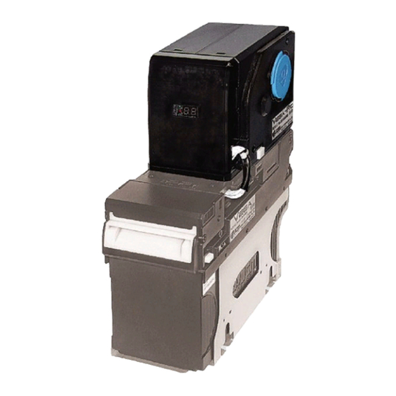
• Outside Dimensions specific actions are given sequential numbers (1., 2., 3., etc.). • Technical Contact Information. VEGA-RC Unit Figure 1-1 VEGA-RC BankNote Recycler Unit (Optional) P/N 960-100190RA_Rev. A {EDP #148851} © 2009, Japan CashMachine Co., Limited 1 - 1... -
Page 14: Model/Type Number Specifications
1. When closing the Rear Cover of the Recycler, Table 1-1 Model Number Specifications ensure that it clicks firmly into place. Model: VEGA-RC - ** - * Caution: Be careful to avoid personal injury to your fingers when closing the (2) (3) Recycler’s Rear Cover. -
Page 15: Unacceptable Banknotes
General Information VEGA-RC™BankNote Recycler Section 1 NACCEPTABLE ANKNOTES The following Banknote types may not recycle correctly, or can cause a Banknote jam and/or dam- age to the Unit’s Transport path (See Figure 1-3). Banknotes exhibiting the following conditions should be avoided: •... -
Page 16: Component Names
Section 1 VEGA-RC™BankNote Recycler General Information Component Names Figure 1-4 illustrates the VEGA-RC primary component parts and their relative location a) Function Button Descriptions d) Rear Cover Open/Close Knob A.Change Display e) Maintenance Knob Cover B.Dispense f) DIP Switch Block C.Restore... -
Page 17: System Configurations
General Information VEGA-RC™BankNote Recycler Section 1 System Configurations Figure 1-5 illustrates a typical VEGA-RC system configuration. Figure 1-5 VEGA-RC System Configuration Destinations Table 1-2 VEGA-RC System Configuration VEGA-RC connected with the VEGA unit PC (Windows 2000/XP) Power Supply (e.g., UAC, MIB232, etc.) Host Machine (Game Machine, Vending Machine, etc.) -
Page 18: Specifications
Note length discrimination (when denomination type is set). *. Acceptable denomination can be selected (Refer to “DIP Switch Configurations” on page 2-1 of Section 2 set for the VEGA-RC denomination). †. Depends on the Host communicataion time lag when connected to the VEGA Unit. -
Page 19: Electrical Specifications
When connected to the VEGA Banknote Validator, the VEGA-RC allows one (1) denomination to be recy- cled at a time. The VEGA-RC can recycle any Banknote accepted by the VEGA Unit, and can hold up to 30 Notes at a time. The improved internal mechanism significantly reduces the chance of a Banknote jamming inside the Recycler Unit. -
Page 20: Technical Contact Information
Section 1 VEGA-RC™BankNote Recycler General Information Technical Contact Information To obtain further Technical Information regarding the VEGA-RC Device, please contact the closest office to your location listed below: Americas & Oceania Asia JCM A JCM G (HK) L MERICAN ORPORATION... -
Page 21: Installation/Operation
Enable self test Disable self test two (2) Latches lock in place between the VEGA-RC and the VEGA Unit body (See Figure 2-2 a). P/N 960-100190RA_Rev. A {EDP #148851} © 2009, Japan CashMachine Co., Limited... -
Page 22: Connector Pin Assignments
Section 2 VEGA-RC™ BankNote Recycler Installation/Operation Connector Pin Assignments Table 2-2 lists the various VEGA-RC to VEGA Unit Receptacle Connector Pin Assignments. Table 2-2 Recycler to Acceptor Receptacle Pin Assignments PHD Connector (Side Type): S14B-PHDSS-B (JST) Socket Housing: PHDR-14VS Contact Type: SPHD-001T-P0.5 Recommended Wire: UL1007 AWG #22~26 Flat Cable (Slit Type) †... -
Page 23: Preventive Maintenance
Unit is initializing; or, perform a manual Drum Winding operation to bring Banknotes to the home position that are not yet stored on the VEGA-RC Drum. NOTE: If a Banknote Jam occurs while closing the Rear Cover, the error condition indicated in Figure 2-6 will occur. -
Page 24: Stacker Full
When the number of recyclable Banknotes within Slot, the Banknote will be stored into the VEGA- VEGA-RC reaches its set limit, or the Full Detec- RC Drum (Stacker). After an inserted Banknote tion Sensor discovers a storage limit equal to 30... -
Page 25: Retrieving All Banknotes
VEGA Insertion Slot. To retrieve recyclable Banknotes from within the VEGA-RC, perform the following steps: 0.5 Seconds 1. Check that the VEGA-RC Seven (7) Segment Interval Display is not indicating a Drum (Stacker) Empty condition. If the VEGA-RC Seven (7) Segment Display is not showing “00”, press the “D”... -
Page 26: Change Display
“A” [ Change Display Pushbutton (Review the Figure 2-20 display). NOTE: After showing the storage limit value for five (5) seconds, the VEGA-RC status will return to the Stand-By Mode. P/N 960-100190RA_Rev. A {EDP #148851} © 2009, Japan CashMachine Co., Limited... -
Page 27: Clearing A Banknote Jam
Clearing a Banknote Jam 6. The jammed Banknote can then be removed by opening the Rear Cover. When a Banknote is jammed in the VEGA-RC, proceed as follows to clear it: 1. Pull the Rear Cover Open/Close Button upward (See Figure 2-24 a). -
Page 28: Cleaning Procedure
Recycler’s Sensors, and Table 2-4 lists their iden- Magnetic and Optical Sensors, Rollers and Belts. tity and specific cleaning preference. If necessary, blow the inside of the Unit clean with Figure 2-26 VEGA-RC Sensor Locations Table 2-4 VEGA Sensor Locations Sensor Cleaning Preference... -
Page 29: Interface Circuit Schematics
Pressurized, Compressed Air Jet Cleaning Figure 2-29 Rear Cover Open for Air Jet Cleaning Interface Circuit Schematics Figure 2-30 illustrates the VEGA-RC TTL Circuit Interface Schematic Diagram. Circuit Interface Figure 2-30 VEGA-RC TTL Schematic Diagram P/N 960-100190RA_Rev. A {EDP #148851} ©... -
Page 30: Operational Flowcharts
Section 2 VEGA-RC™ BankNote Recycler Installation/Operation Operational Flowcharts Figure 2-31 depicts part one of the basic VEGA-RC Banknote acceptance flow process (Intiializing). a) Initializing A) From Stand-By (See Figure 2-33 on page 2-12) b) Stand-By c) Command Input from VEGA Unit? -
Page 31: Operational Flowcharts (Continued 2)
Installation/Operation VEGA-RC™ BankNote Recycler Section 2 Operational Flowcharts (Continued 2) Figure 2-32 depicts part two of a typical VEGA-RC Banknote acceptance flow process (Command). B) Command Flow a) Restore Command? B1) To Restore Flow (See Figure 2-34 on page 2-12) -
Page 32: Operational Flowcharts (Continued 3)
VEGA-RC™ BankNote Recycler Installation/Operation Operational Flowcharts (Continued 3) Figure 2-33 depicts part three of a typical VEGA-RC Banknote acceptance flow process (Error Clearing). D) Clearing Error Flow a) Is Error Clearing Completed? A) To Stand-By (See Figure 2-29 on page... -
Page 33: Operational Flowcharts (Continued 4)
Figure 2-36 on page 2-13) Figure 2-35 VEGA-RC Banknote Recycler Operational Flowchart (Dispense Mode) Figure 2-36 depicts part six of a typical VEGA-RC Banknote acceptance flow process (Clear Jam). E) Begin Clearing a JAM a) Error Notification to VEGA Unit... -
Page 34: Operational Flowcharts (Continued 5)
E) To Clear JAM Flow Process (See Figure 2-36 on page 2-13) Figure 2-37 VEGA-RC Banknote Recycler Operational Flowchart (Retrieving Mode) Figure 2-38 depicts part eight of a typical VEGA-RC Banknote acceptance flow process (Collect Log). B4) Collect Log Flow a) Send Log to VEGA Unit... -
Page 35: Operational Flowcharts (Continued 6)
Installation/Operation VEGA-RC™ BankNote Recycler Section 2 Operational Flowcharts (Continued 6) Figure 2-39 depicts part nine of a typical VEGA-RC Banknote acceptance flow process (Key Input). C) Key Input Flow a) Restore Key? C1) Restore Key Input Notification to the VEGA Unit... - Page 36 Section 2 VEGA-RC™ BankNote Recycler Installation/Operation THIS PAGE INTENTIONALLY LEFT BLANK P/N 960-100190RA_Rev. A {EDP #148851} © 2009, Japan CashMachine Co., Limited 2 - 1 6...
-
Page 37: Communications
VEGA-RC™ BankNote Recycler S e c t i o n 3 3 COMMUNICATIONS This section was intentionally left out due to a Non Disclosure Agreement requirement. If this information is required, please contact: Americas & Oceania Asia JCM A JCM G... - Page 38 VEGA-RC™BankNote Recycler THIS PAGE INTENTIONALLY LEFT BLANK P/N 960-100190RA_Rev. A {EDP #148851} © 2009, Japan CashMachine Co., Limited 3 - 2...
-
Page 39: Disassembly/Reassembly
Board, be sure to ), and remove the Front Cover from the remove the Display Protection Sticker VEGA-RC Unit (See Figure 4-1 b). located on the Seven (7) Segment Display of the new CPU Board before installing it. -
Page 40: Figure 4-3 Cover (R) & Cover (L) Removal
3. Remove the four (4) mounting screws (See Figure 4-5 Motor Removal Figure 4-4 a , & a ) from the bottom base of the VEGA-RC Unit. 6. Remove the two (2) Motor Mounting Screws (4-5 d & d ) retaining the Motor to 4. -
Page 41: Open/Close Detection Board Removal
Figure 4-9 c). 2. Remove the single (1) Sensor Bracket Mounting Screw (See Figure 4-8 a) retaining the Sensor Bracket to the VEGA-RC Unit (See Figure 4-8 b), and remove the Sensor Bracket from the Unit. Figure 4-9 Course Reversing Assembly Removal... -
Page 42: Rubber Pulley & Drive Roller Removal
(See Figure 4-12 a & a ) holding the Tray Cover in place (See Figure 4-12 b), 2. Remove the Tray Cover from the VEGA-RC Unit. Figure 4-10 Encoder Board & Position Detection Board Removal Figure 4-12 Tray Cover & Tray Removal Rubber Pulley &... -
Page 43: Figure 4-13 Frame Body Shaft Assy. Removal
) from the ends both Upper and Lower Frame Body Shaft Assembly, and take the Frame Body Assemblies out of the VEGA-RC Unit (See Figure 4-13 j). 10. Slide the Belt Bobbin (See Figure 4-14 a & ) to the inside, and pull the single (1) pin out of the Shaft (See Figure 4-14 b). -
Page 44: Clear & Metallic Edge Belt Replacement
1. Install the Right Frame Body Shaft (R) (See Figure 4-16 a) and the Left Frame Body Shaft (L) (See Figure 4-16 b) with both sets of Belts attached to the VEGA-RC Unit. Figure 4-18 Tray & Tray Cover Installation NOTE: After reinstalling the Tray, turn the Bobbins by hand to take up any excess slack in the Belts. -
Page 45: Wiring Diagrams
VEGA-RC™ BankNote Recycler S e c t i o n 5 5 WIRING DIAGRAMS This chapter provides the VEGA-RC Bill Recycler • System Wiring Diagram* Frame wiring diagram for the following items: VEGA-RC System Wiring Diagram Figure 5-1 VEGA-RC System Wiring Diagram * CN2 is a Connector for additional Interfaces. - Page 46 Section 5 VEGA-RC™ BankNote Recycler Wiring Diagrams THIS PAGE INTENTIONALLY LEFT BLANK P/N 960-100190RA_Rev. A {EDP #148851} © 2009, Japan CashMachine Co., Limited 5 - 2...
-
Page 47: Performance Tests
Power Supply (e.g., UAC, MIB232, etc.). Figure 6-1 VEGA-RC Unit Test Connections NOTE: Only short the 3rd pin (TXD) and the 4th pin (RXD) of the VEGA-RC Main CPU Board CN3 to each other when performing a Communication Loop Test, otherwise leave them as individual pin connections. -
Page 48: Display And Operation
Seven (7) Segment Display, press proceed as follows: the “A” (Change Display) to start the selected 1. Set DIP Switch No.8 of the VEGA-RC ON. Test. 2. Apply power to the VEGA RC by turning the NOTE: Pressing the “A”... -
Page 49: Figure 6-5 Function Key Test (Ts = Test Switch)
” followed by “ ”. Switches located on the VEGA-RC DIP Switch 3. On the VEGA-RC DIP Switch, set Switches #1 Block is operating correctly. This is accomplished through #8 OFF. The Seven (7) Segment Display by manually changing each Switch settings on the should indicate “... -
Page 50: Figure 6-7 Typical Dip Switch Test Display
Display should indicate “ ” followed by “ ”. and #8 to ON. The Seven (7) Segment Display 3. Open the Rear Cover of the VEGA-RC and should indicate “ ” followed by “ ”. verify that the Seven (7) Segment Display indi- 6. -
Page 51: Figure 6-10 Escrow Sensor Off (Pi Of)
Performance Tests VEGA-RC™BankNote Recycler Section 6 VEGA RC Flap Sensor Input Test This test is performed to verify the VEGA-RC Flap 0.5 Seconds Sensors’ status. To perform the VEGA-RC Flap Sensor Input Test, proceed as follows: Figure 6-10 Escrow Sensor OFF (PI oF) Use Pushbutton “B”... -
Page 52: Test T1 - Position Detection Sensor 1 A/D Value Display Test
0.5 Seconds complete. Press and hold-down the “ ” Pushbut- ton on the VEGA-RC Unit for 3 seconds to return the Unit to Test Selection Mode. Figure 6-16 Position Detection Sensor 1 Test NOTE: While the A\D value is showing, Test T3 - Full/Empty Detection Sensors 1 the Green LED will blink at 0.5 second... -
Page 53: Test T7 - Communication Loop Test
30 Hexadecimal. If the displayed A/D value back Test as shown in Figure 6-1. is less than 30H then the Sensor is 3. On the VEGA-RC, ensure that DIP Switch #8 is properly detecting the Metallic Silver set to the “... -
Page 54: Test T9A - Transport Belt Dirt Confirmation Test
30H indicates that the Sensor is detecting the Metallic Silver coated end portion of This test is used to check for dirt on the VEGA-RC the Transport Belt used for determining the Transport Film Belts. The Test is accomplished by Empty/Full status of the VEGA-RC Drum. -
Page 55: Figure 6-26 Full/Empty Detection Sensor 2 Empty A/D Value (E@05)
Indication continues showing the A/D Value until the “D” (Retrieve) Pushbutton is pressed a second time. 3. Press Pushbutton “D” on the VEGA-RC Unit. The Seven (7) Segment Display will indicate an A/D Value for Full/Empty Detection Sensor #2. The value being displayed represents the Sensor reading that was taken at a time when the internal Film Belt Bobbin was “Empty”, or nearly empty. - Page 56 Section 6 VEGA-RC™BankNote Recycler Performance Tests THIS PAGE INTENTIONALLY LEFT BLANK P/N 960-100190RA_Rev. A {EDP #148851} © 2009, Japan CashMachine Co., Limited 6 - 1 0...
-
Page 57: Exploded Views And Parts Lists
Entire VEGA-RC Exploded View and Parts Exploded View and Parts List List (Part 5) Entire VEGA-RC Exploded View 1 Figure 7-1 Entire VEGA-RC Exploded View (Part 1) P/N 960-100190RA_Rev. A {EDP #148851} © 2009, Japan CashMachine Co., Limited 7 - 1... -
Page 58: Entire Vega-Rc Parts List 1
Section 7 VEGA-RC™BankNote Recycler Exploded Views and Parts Lists Entire VEGA-RC Parts List 1 Table 7-1 Entire VEGA-RC Parts List (Part 1) Description Qty. Remark Ref N EDP N JAC N 2.6x6 Phillips, Binding Self Tightening 104081 186-266000R 3M(Black) 144781... -
Page 59: Entire Vega-Rc Exploded View 2
Exploded Views and Parts Lists VEGA-RC™BankNote Recycler Section 7 Entire VEGA-RC Exploded View 2 Figure 7-2 Entire VEGA-RC Exploded View (Part 2) P/N 960-100190RA_Rev. A {EDP #148851} © 2009, Japan CashMachine Co., Limited 7 - 3... -
Page 60: Entire Vega-Rc Parts List 2
Section 7 VEGA-RC™BankNote Recycler Exploded Views and Parts Lists Entire VEGA-RC Parts List 2 Table 7-2 Entire VEGA-RC Parts List (Part 2) Description Qty. Remark Ref N EDP N JAC N M3x6 Pan Head Polycarbonate 104332 186-360000R Screw 144786 900-200370R... -
Page 61: Entire Vega-Rc Exploded View 3
Exploded Views and Parts Lists VEGA-RC™BankNote Recycler Section 7 Entire VEGA-RC Exploded View 3 Figure 7-3 Entire VEGA-RC Exploded View (Part 3) P/N 960-100190RA_Rev. A {EDP #148851} © 2009, Japan CashMachine Co., Limited 7 - 5... -
Page 62: Entire Vega-Rc Parts List 3
Section 7 VEGA-RC™BankNote Recycler Exploded Views and Parts Lists Entire VEGA-RC Parts List 3 Table 7-3 Entire VEGA-RC Parts List (Part 3) Description Qty. Remark Ref N EDP N JAC N M2.6x6 Pan Head Screw with 005555 186-260106 Washer 3M... -
Page 63: Entire Vega-Rc Exploded View 4
Exploded Views and Parts Lists VEGA-RC™BankNote Recycler Section 7 Entire VEGA-RC Exploded View 4 Figure 7-4 Entire VEGA-RC Exploded View (Part 4) P/N 960-100190RA_Rev. A {EDP #148851} © 2009, Japan CashMachine Co., Limited 7 - 7... -
Page 64: Entire Vega-Rc Parts List 4
Section 7 VEGA-RC™BankNote Recycler Exploded Views and Parts Lists Entire VEGA-RC Parts List 4 Table 7-4 Entire VEGA-RC Parts List (Part 4) Description Qty. Remark Ref N EDP N JAC N 2.6x6 Phillips, Binding Self Tightening 104081 186-266000R 3M (Black) -
Page 65: Entire Vega-Rc Exploded View 5
Exploded Views and Parts Lists VEGA-RC™BankNote Recycler Section 7 Entire VEGA-RC Exploded View 5 Figure 7-5 Entire VEGA-RC Exploded View (Part 5) P/N 960-100190RA_Rev. A {EDP #148851} © 2009, Japan CashMachine Co., Limited 7 - 9... -
Page 66: Entire Vega-Rc Parts List 5
Section 7 VEGA-RC™BankNote Recycler Exploded Views and Parts Lists Entire VEGA-RC Parts List 5 Table 7-5 Entire VEGA-RC Parts List (Part 5) Description Qty. Remark Ref N EDP N JAC N Φ3 E-Ring 091516 200-100984R 144725 900-200373R IDLE GEAR 2... -
Page 67: Figure 7-6 Entire Vega-Rc Exploded View (Part 6)
Exploded Views and Parts Lists VEGA-RC™BankNote Recycler Section 7 Entire VEGA-RC Exploded View 6 Figure 7-6 Entire VEGA-RC Exploded View (Part 6) P/N 960-100190RA_Rev. A {EDP #148851} © 2009, Japan CashMachine Co., Limited 7 - 1 1... -
Page 68: Entire Vega-Rc Parts List 6
Section 7 VEGA-RC™BankNote Recycler Exploded Views and Parts Lists Entire VEGA-RC Parts List 6 Table 7-6 Entire VEGA-RC Parts List (Part 6) Description Qty. Remark Ref N EDP N JAC N 144767 900-200376R GUIDE ROLLER 144742 900-200380R IDLE BEAM 144731... -
Page 69: Vega-Rc Tray Assembly Exploded View
Exploded Views and Parts Lists VEGA-RC™BankNote Recycler Section 7 VEGA-RC Tray Assembly Exploded View Figure 7-7 VEGA-RC Tray Assembly Exploded View P/N 960-100190RA_Rev. A {EDP #148851} © 2009, Japan CashMachine Co., Limited 7 - 1 3... -
Page 70: Vega-Rc Tray Assembly Parts List
Section 7 VEGA-RC™BankNote Recycler Exploded Views and Parts Lists VEGA-RC Tray Assembly Parts List Table 7-7 VEGA-RC Tray Assembly Parts List Description Qty. Remark Ref N EDP N JAC N 144777 900-200383R TRAY COVER 144791 900-200384R TIGHTENING CS 144758 900-200385R... -
Page 71: Vega-Rc Fb Upper Shaft Assembly Exploded View
Exploded Views and Parts Lists VEGA-RC™BankNote Recycler Section 7 VEGA-RC FB Upper Shaft Assembly Exploded View Figure 7-8 VEGA-RC FB Upper Shaft Assembly Exploded View P/N 960-100190RA_Rev. A {EDP #148851} © 2009, Japan CashMachine Co., Limited 7 - 1 5... -
Page 72: Vega-Rc Fb Upper Shaft Assembly Parts List
Section 7 VEGA-RC™BankNote Recycler Exploded Views and Parts Lists VEGA-RC FB Upper Shaft Assembly Parts List Table 7-8 VEGA-RC FB Upper Shaft Assembly Parts List Description Qty. Remark Ref N EDP N JAC N 144773 200-200783R BOBBIN CAP 144751 900-200390R... -
Page 73: Vega-Rc Motor Unit Exploded View
Exploded Views and Parts Lists VEGA-RC™BankNote Recycler Section 7 VEGA-RC Motor Unit Exploded View Figure 7-9 VEGA-RC Motor Unit Exploded View P/N 960-100190RA_Rev. A {EDP #148851} © 2009, Japan CashMachine Co., Limited 7 - 1 7... -
Page 74: Vega-Rc Motor Unit Parts List
Section 7 VEGA-RC™BankNote Recycler Exploded Views and Parts Lists VEGA-RC Motor Unit Parts List Table 7-9 VEGA-RC Motor Unit Parts List Description Qty. Remark Ref N EDP N JAC N 144760 900-200397R REMOVAL LATCH 144780 900-200398R BOTTOM 144726 900-200399R RC MOTOR GEAR Φ3x18 Parallel Pin Sustainer (Hard) -
Page 75: Vega-Rc Course Reversing Assembly Exploded View
Exploded Views and Parts Lists VEGA-RC™BankNote Recycler Section 7 VEGA-RC Course Reversing Assembly Exploded View Figure 7-10 VEGA-RC Course Reversing Assembly Exploded View P/N 960-100190RA_Rev. A {EDP #148851} © 2009, Japan CashMachine Co., Limited 7 - 1 9... -
Page 76: Vega-Rc Course Reversing Assembly Parts List
Section 7 VEGA-RC™BankNote Recycler Exploded Views and Parts Lists VEGA-RC Course Reversing Assembly Parts List Table 7-10 VEGA-RC Course Reversing Assembly Parts List Description Qty. Remark Ref N EDP N JAC N 144761 200-200787R ENCODER 144775 900-200403R COURSE RVERSING GUIDE... -
Page 77: Vega-Rc Fb Lower Shaft Assembly Exploded View
Exploded Views and Parts Lists VEGA-RC™BankNote Recycler Section 7 VEGA-RC FB Lower Shaft Assembly Exploded View Figure 7-11 VEGA-RC FB Lower Shaft Assembly Exploded View P/N 960-100190RA_Rev. A {EDP #148851} © 2009, Japan CashMachine Co., Limited 7 - 2 1... -
Page 78: Vega-Rc Fb Lower Shaft Assembly Parts List
Section 7 VEGA-RC™BankNote Recycler Exploded Views and Parts Lists VEGA-RC FB Lower Shaft Assembly Parts List Table 7-11 VEGA-RC FB Lower Shaft Assembly Parts List Description Qty. Remark Ref N EDP N JAC N 1001 144743 200-200773R SET PIN 15... -
Page 79: Index
… Faults … table listings of Tool Requirements Flowcharts … … workbench & field 2-10 operational VEGA-RC Unit Installation … … photo of a steps for performing an JCM Contact Information … Address and Telephone Numbers for Warning … liquid damage …... - Page 80 Section 8 VEGA-RC™BankNote Recycler Index THIS PAGE INTENTIONALLY LEFT BLANK P/N 960-100190RA_Rev. A {EDP #148851} © 2009, Japan CashMachine Co., Limited 8 - 2...
-
Page 81: A Troubleshooting
Causes Solutions Codes Remove the Banknote that remains in the Drum of the VEGA-RC [Restore Error] A Banknote remains in the VEGA- Unit. (The remaining Banknote is NOT counted as a stored Banknote RC internal Drum when power is re-supplied. - Page 82 NOTE: When a command from the Host Machine is being received, or a dispense request occurs from pressing the VEGA-RC Pushbutton, or when an Electrical Power failure occurs before the dispensing process begins, the processing Banknote is counted as a dispense completed Banknote.
-
Page 83: Warning Codes
Transport Encoder Board CN1, CPU Board CN4 If the error is not resolved, change the above related component(s). Check that the VEGA-RC stacking denomination matches the VEGA Receive different denomination information Unit’s command denomination. (Confirm that both Unit DIP Switch (Money Class) during communication. -
Page 84: Jcm Contact Information
Appendix A VEGA-RC™BankNote Recycler Troubleshooting JCM Contact Information Americas & Oceania Asia JCM A JCM G (HK) L MERICAN ORPORATION Phone: +1-702-651-0000 Phone: +852-2429-7187 Fax: +1-702-644-5512 Fax: +852-2929-7003 925 Pilot Road, Las Vegas, NV 89119 Unit 1-7, 3/F., Favor Industrial Centre E-mail: customerservice@jcm-american.com... - Page 85 A/D Value – an Analog to Digital Converter Value (normally expressed in a range from 00 to FF Hexadecimal) representing the reading obtained from internal Optical Sensors in the VEGA-RC during a diagnostic testing mode … See Page 6-6 Banknote Jam – on occasion, wrinkled or damaged Banknotes become stuck ...
- Page 86 BVs Transport Assembly. The position of the Stacker Flap determines whether the Banknote currently being validated will be sent to the VEGA-BV Cash Box or to the VEGA-RC Recycler Drum (Stacker) … See Page 6-3. Also see Page 2-6 of the VEGA Operation and Maintenance ...
- Page 87 Light Emitting Diode and a Photo-sensitive Transistor Circuit … See Figure 2-31 on Page 2-10 23 Recycler– another name for the VEGA-RC, an optional add-on device for the VEGA-BV. The Recycler adds additional capability and functionality to the VEGA-BV Unit ...
- Page 88 VEGA Banknote Validation system … See Page 1-1 30 VEGA-RC – a 30-note Banknote Recycler Unit option that can be used in conjunction with the VEGA-BV Unit. The VEGA-RC can be programmed to accept and ...
- Page 89 VEGA-RC™BankNote Recycler P/N 960-100190RA_Rev. A {EDP #148851} © 2009, Japan CashMachine Co., Limited...
- Page 90 VEGA-RC™BankNote Recycler Support: http://www.jcmglobal.com/en/contact/default.aspx Web-Site: http://www.jcmglobal.com Issue #4078-SME-01-00 P/N 960-100190RA_Rev. A {EDP #148851} © 2009, Japan CashMachine Co., Limited...
Need help?
Do you have a question about the VEGA-RC and is the answer not in the manual?
Questions and answers