Sign In
Upload
Download
Table of Contents
Contents
Add to my manuals
Delete from my manuals
Share
URL of this page:
HTML Link:
Bookmark this page
Add
Manual will be automatically added to "My Manuals"
Print this page
×
Bookmark added
×
Added to my manuals
Manuals
Brands
Thermo Scientific Manuals
Mixer
Maxi Mix II
Operation manual and parts list
Thermo Scientific Maxi Mix II Operation Manual And Parts List
Vortex mixer
Hide thumbs
1
Table Of Contents
2
3
4
5
6
7
8
9
10
11
12
13
14
15
16
page
of
16
Go
/
16
Contents
Table of Contents
Bookmarks
Table of Contents
Table of Contents
General Specifications
Declaration of Conformity
Environmental Conditions
Safety Information
Important Information
Warnings
Introduction
Intended Use
Principles of Operation
Installation
Unpackaging
Site Selection
Specifications
Operation
Power Switch
Speed Control
Maintenance and Servicing
To Replace the Power Switch
To Replace Rheostat (Speed Control)
To Replace Microswitch
To Replace Motor
To Replace Damper Springs
To Replace Mixing Surface Disc
To Install Single Cup Mixing Head
Problem Solving Guide
Replacement Parts List
Ordering Procedures
Exploded View
One Year Limited Warranty
Advertisement
Quick Links
1
Table of Contents
2
General Specifications
3
Specifications
4
Maintenance and Servicing
5
Problem Solving Guide
6
Replacement Parts List
Download this manual
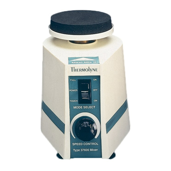
Maxi Mix
II
®
Vortex Mixer
Operation Manual and Parts List
M
N
ODEL
UMBERS
M37615
M37614
M37610-33
M37610-33CN
LT1254X1 • 9/19/08
Table of
Contents
Previous
Page
Next
Page
1
2
3
4
5
Advertisement
Table of Contents
Need help?
Do you have a question about the Maxi Mix II and is the answer not in the manual?
Ask a question
Questions and answers
Related Manuals for Thermo Scientific Maxi Mix II
Mixer Thermo Scientific M37615 Operation Manual And Parts List
Vortex mixer (16 pages)
This manual is also suitable for:
M37615
M37614
M37610-33
M37610-33cn
Table of Contents
Save PDF
Print
Rename the bookmark
Delete bookmark?
Delete from my manuals?
Login
Sign In
OR
Sign in with Facebook
Sign in with Google
Upload manual
Upload from disk
Upload from URL


Need help?
Do you have a question about the Maxi Mix II and is the answer not in the manual?
Questions and answers