Advertisement
Quick Links
Advertisement

Related Manuals for ESP VFC2.55G

Summary of Contents for ESP VFC2.55G
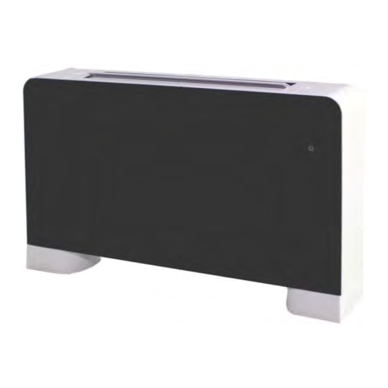
- Page 1 Glass Thermovec Installation and Maintenance Manual...
-
Page 2: Table Of Contents
CONTENTS 1.Preface 2.Safety precautions 2.1 Mark Notes 2.2 Icon Notes 2.3 Warning 2.4 Attention 3 Specifications 3.1 Parameter list 3.2 Working condition 3.3 Overall dimensions 3.4 The working principle of units 3.5 Unit characteristics 4 Installation 4.1 Installation precautions 4.2 Installation note places 4.3 Install note schemes 4.4 Conduit connections 5 Usage... -
Page 3: Preface
1. Preface Thank you for choosing Earth Save Products Limited’s Glass Thermovec. Please read this installation and maintenance manual carefully before attempting to install, use or maintain your Thermovec. Your Thermovec must be installed by a suitably qualified and experienced technician to ensure that it is installed safely and correct and also to comply with warranty requirements. -
Page 4: Safety Precautions
Switch off your Thermovec before cleaning the case or the filters Switch off your Thermovec before carrying out any maintenance Do not modify or change any of the internal devices without consulting ESP Ltd. General Precautions: Some basic safety rules should be followed when using any product that uses electricity and water, such as: Do not touch the appliance with wet skin. -
Page 5: Specifications
Packing List. Installation Thermovec Manual Screw Cap Remote Template Mounting Condensate Wall Plugs Screws Feet Brackets Drain Pipe Parameters ESP VFC ESP VFC ESP VFC ESP VFC ESP VFC Units Unit Model 2.55G 3.95G 5.75G 7.2G 9.4G 9400 3950 5750 Heating Capacity①... -
Page 6: Working Condition
Heating ambient temperature: 5-29℃, flow water temperature: 35-70℃. Cooling ambient temperature: 9-35℃, return water temperature: 5-20℃. Dimensions 3.3.1 Product model: VFC 2.55/3.95/5.75/7.2/9.4G Unit Model VFC5.75G VFC 7.2G VFC 9. 4G VFC2.55G VFC 3.95G 1095 1295 1495 4 of 16 V1.0... -
Page 7: Unit Characteristics
How it works The Thermovec is supplied by hot or cold water from your ASHP. It draws air in from the room in which it is installed, blows that air over a heat exchanger and exhausts the air into that room. The temperature of the room is controlled by the Thermovec and the water flow is controlled by a three-way valve. -
Page 8: Installation
Positioning the unit Avoid installing the unit in proximity to other heat sources, in direct sunlight, in damp areas or where it is likely to come into contact with water. Areas contaminated with combustible fumes and high frequency radio signals should also be avoided. Ensure that: The wall on which the unit is to be installed is strong enough to support the weight. - Page 9 Mounting the Thermovec Using the paper template, trace the position of the bracket holes. Thermovec Feet. If you are going to use the Thermovec feet, they must be attached before installation as shown in the following two diagrams. First, lay the unit down carefully to protect both the Thermovec and the surface on which it is...
- Page 10 Fix the two brackets to the wall using suitable fixings: the supplied wall plugs are only suitable for certain types of walls. Do not tighten until final adjustment to ‘level’ has been made and checked. 4.Installation Connecting the Pipework. The distribution pipework should be hot Flow flushed and pressure tested before the Thermovec is connected.
- Page 11 Bleeding the Thermovec The Thermovec must be bled before power is applied i.e. before it is switched on. Use a screwdriver to open the bleed valve on the side of the Thermovec until all air is expelled from the unit then close the valve again taking care not to over-tighten it.
- Page 12 Mode. Used to toggle between modes. Note: If no button has been pressed for 1 min, the control panel will be hidden. Simply touch the control panel area to display the controls. Using the Control Panel Turning the Thermovec on/Off Pressing the on/off button for 0.5Secs will power the unit on/off.
- Page 13 After 5 secs, the changed setting will be saved and the display will revert to the default Changing the Fan Speed To change the fan speed, simply press the fan speed button to toggle between 3 fan speed or ‘auto’. For ‘boost mode’, press and hold the fan speed button for 5 seconds. In boost mode, press the fan speed button once to revert to the previously set fan speed: To Switch on Boost mode: Press and hold...
- Page 14 Setting the Sleep Mode Sleep mode can be used to turn the Thermovec off after a period from 1-11 hours then back on again after a period of 1-11 hours: From the main display select a value from 1 to press to start 11 (hours before...
- Page 15 Checking the Coil temperature To check the coil temperature, press the buttons simultaneously. This will display the coil temperature for 3 secs before the display reverts to the default display. This isfor information only and cannot be changed. After 3 Secs, the display will revert to the default.
- Page 16 Locking the Control Panel To lock the control panel, press and hold the power button for 5 seconds. Repeat to unlock the panel: Symbol signifies that control panel is locked Press and hold for 5 secs to lock/unlock Fault Display In the unlikely event that your Thermovec develops a fault, it will be displayed as a code.
-
Page 17: Maintenance
Any repairs should be undertaken by qualified technicians using genuine spare parts supplied by Earth Save Products Ltd. Should a leak develop, the unit should be switched off and advice sought from your installer or the ESP Ltd Technical Department. Correct Disposal of this product This product should not be disposed of with other household waste but recycled in accordance with current Government policy. -
Page 18: Pcb I/O Port
Wiring Details Thermovecs can be connected together and incorporated into a building management system: PCB I/O Ports 16 of 16 V1.0...
Need help?
Do you have a question about the VFC2.55G and is the answer not in the manual?
Questions and answers