Table of Contents
Advertisement
For your safety
Please read this instruction manual before you use the Hand
Pallet Truck!
Contents: Part List and Instruction
Model .:
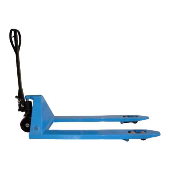
XTN 540-1150
Please keep these instructions for future reference.
Safety-Lifting Group
Unit 23 Atlantic Road , Avonbridge Trading Estate ,
Avonmouth , Bristol , BS16 1XB
Tel: + 4 4 (0)1179 381600 Fax: + 4 4 (0)1179 381602
www.safety-lifting.com
1
Advertisement
Table of Contents

Subscribe to Our Youtube Channel
Related Manuals for LoadSurfer XTN 540-1150

Summary of Contents for LoadSurfer XTN 540-1150
- Page 1 Please read this instruction manual before you use the Hand Pallet Truck! Contents: Part List and Instruction Model .: XTN 540-1150 Please keep these instructions for future reference. Safety-Lifting Group Unit 23 Atlantic Road , Avonbridge Trading Estate , Avonmouth , Bristol , BS16 1XB Tel: + 4 4 (0)1179 381600 Fax: + 4 4 (0)1179 381602 www.safety-lifting.com...
-
Page 2: Table Of Contents
Table of Contents Safety rules and Instruction .............2 Handle assembling ............2 – 4 Setting of Realse Valve ............4 – 5 How to work with Hand Pallet Truck ........6 – 7 Service and Guarantee ............7 – 8 Fault diagnosis, Examination, Disposal ......... - Page 3 Assembling the Handle 1.4 Tools you need Hammer 180g , medium size screw driver. 3 mm Punch 1.5 Parts Handle(45), Handle axis (46), 2x spring pin (23). These parts are supplied in a plastic bag, which is attached to the handle Note The number of the handle and pump should be the same 2 Assembling the Handle...
-
Page 4: Setting Of Realse Valve
2.1 Pull down the lever to the Lifting position. (lifting ) 2.2 Pass the adjusting nut (Part No. 59), adjusting bolt (Part No.58) and chain (Part No. 60) assembly through the hole of axle (Part No. 46) with your hand Insert the handle onto the pump piston (Part No. - Page 5 3 To adjust the release device On the handle of this hand pallet truck, you can find the lever, which operates in three positions Lower ........ = Lowering the fork ......LOWER-Position Drive ......... = Drive the truck ........Drive-Position Raise ........
-
Page 6: How To Work With Hand Pallet Truck
4.0 Handling 4.1 Driving and Steering the truck with Handle The handle is adjusted directly to the steering wheels. The steering wheels will follow the position of the handle. Pict 3... -
Page 7: Service And Guarantee
4.2 How to take the load Drive the truck slowly in front of the pallet. Then, drive the fork of the truck under the pallet up to end of the fork length. (Pict 3.A). Lift the load by pumping the handle at Raise position.The load must be on the center of the hand pallet truck. - Page 8 5.4 Lubrication All bearings and shafts are provided with long-life grease at the factory. You only need provide long-life grease at monthly intervals or after each time the truck is cleaned thoroughly to the lubrication points. 6.0 Guide to safety operation 6.1 Operator should read all warning signs and instruction here and on the pallet truck before using this truck 6.2 Do not operate a hand pallet truck unless you are familiar with it and have...
- Page 9 6.16 Whilst the goods are being transported all none operational staff should be at a minimum distance of 600mm. 6.17 At service work, it is not allowed to scatter parts. 6.18 Under any special conditions or environments, the operator should carry out all relevant risk assessments and method statements before commencing work with the pallet truck 6.19 It is forbidden to use the pallet truck if there is a risk that the pallet truck and...
-
Page 10: Fault Diagnosis, Examination, Disposal
8.0 TROUBLE SHOOTING Trouble Clause Fixing Methods The forks cannot be up at The hydraulic oil is not enough Pour in the oil the max height - Without hydraulic oil - Fill in the oil - The oil has impurities - Change the oil The fork cannot be lifted - The nut (Part No. -
Page 11: Assembling Break
Assembling break into Hand Pallet truck 1. Unscrew the screw pin of the break 2. Use a hammer and pin driver to remove spring pin at the steering wheel (part No. 23) 3. Remove the wheels (Part No. 26) and the steering wheel axis (Part No. -
Page 12: Part List
Part List XTN 540 - 1150 Part No Description Quant. Part No Description Quant. Plunger Piston Ball housing Steel Ball Ø5 Dust Seal Ø18 - Ø26 - 4/6 O-ring Ø17.8 x 2.4 Handle BTN - 2500 Back-up ring Ø18 x Ø22 x 1.25 Hanle Axis E-ring Ø20 Spring Pin Ø3 x 25...
Need help?
Do you have a question about the XTN 540-1150 and is the answer not in the manual?
Questions and answers