Table of Contents
Advertisement
Advertisement
Table of Contents

Related Manuals for Apollo FOX

Summary of Contents for Apollo FOX
-
Page 1: Maintenance Manual
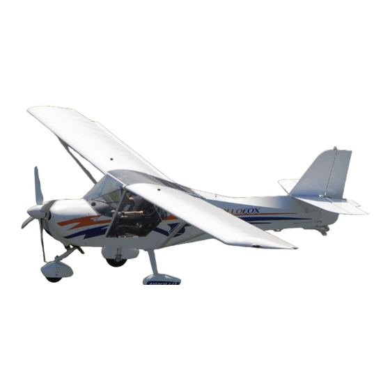
Pilot’s Operating Handbook Maintenance Manual APOLLO FOX Issue: 29.08.2014... - Page 2 APOLLO FOX Aerodynamically Controlled Microlight Aircraft Aircraft Name - Type: Apollo Fox Manufacturer’s address: 3300. Hungary Mester u, 3. Eger Serial Number: Aircraft Registration: Date of Issue: 29.09.2014...
- Page 3 The presented microlight aircraft can be operated in accordance with limitations and information contained in this handbook. 0.1 RECORD OF REVISIONS This page with the table of record of revision enables users to enter revisions or amendments issued in the form of bulletins and to substitute non-existing pages with new ones.
- Page 4 0.2 LIST OF EFFECTIVE PAGES Chapter Page Date Chapter Page Date Chapter Page Date...
-
Page 5: Table Of Contents
0.2.1 TABLE OF CONTENTS Chapter General ............Operating Limitations ......... Operating data and procedures ....Normal Procedures........Emergency Procedures....... Performance..........Supplements.......... -
Page 6: General
1. GENERAL TABLE OF CONTENTS 1.1 ............... Introduction 1.2 ............ Certification Basis 1.3 ......... Definition of denotations 1.4 ............Brief Description 1.4.1 ............Aircraft Type 1.4.2 ..............Propeller 1.4.3 ............... Power Unit 1.4.4 ...... Three-View Drawing of the aircraft 1.4.5 ..........Aircraft dimensions 1.4.6 ............ - Page 7 1.1 Introduction The purpose of this handbook is to provide information for personnel towards increasing safety and efficient aircraft operation. It includes necessary instructions for pilots and additional data provided by the manufacturer based on calculations, loading tests and test flight records. Pilots shall be acquainted with the content of this handbook and comply with its limitations while operating the aircraft.
- Page 8 Halley Ltd. After producing hundreds of weightshift controlled aircrafts the birth of Apollo-Fox was a turning point in the profile of the Company. Many years of experiences gained during the production and operation of other Hungarian aircraft types helped us in the contemplation and construction.
- Page 9 1.4.4 Three view drawing of the aircraft...
- Page 10 1.4.5 Aircraft Dimensions Wing span..................9.2 m Length..................5.75 m Wing folded up length..............6.47 m Propeller diameter..............1.70 m Height (nose gear version) ............2.28 m Height, tail wheel version (windshield)..........1.78 m Cockpit width................1.10 m Number of seats ................2 Wing surface loading ............39.13 kg/m Wing area ................
- Page 11 Track................... 1.85 m Wheel base ................ 1.45 m Main landing gear wheel tire ..........35x15 cm Tire pressure ..............1,7 bar Nose wheel tire ..............12x4 cm Tire pressure ..............1,5 bar...
-
Page 12: Operating Limitations
2. OPERATING LIMITATIONS TABLE OF CONTENTS 2.1 ...............Introduction 2.2 ..........Airspeed Limitations 2.3 ........Airspeed Indicator Marking 2.4 ........Engine Instruments Marking 2.5 ............Power Unit Data 2.6 ..............Weights 2.7 ........Centre of Gravity Position 2.8................Loading 2.9 ..........Flight Load Factors 2.10 ............ - Page 13 2.1 Introduction This chapter contains operating limitations, instrument markings and basic placards necessary for safe operation of the microlight, its engine, standard systems and equipment. 2.2 Speed Limitations Related speed limits are summarised in the table below: Speed km/h Remarks Never Do not exceed this speed in any exceed speed...
- Page 14 It is allowed to fly with opened or removed door/s The maximum IAS with opened door is 120 km/h, avoid slip manoeuvre with door/s open. In case of opened door and higher airspeed the doors can damage the wings undersurface! The maximum IAS with removed door/s 140 km/h Both cases...
- Page 15 2.5 Power Unit Data Engine model ........ROTAX 912 UL-ULS Max. power - take-off ......80-100 HP - continuous ...... 79-89 HP Max. engine speed (MSL) - take-off ..5800 r. p .m. (max. 1 min.) - continuous .... .5500 r. p .m. (max. 5 min.) Max.
-
Page 16: Propeller
This engine is not certified for aircraft, and failure may occur at WARNING any time! The pilot bears full responsibility for the consequences of it’s failure. Propeller manufacturer: ........DM prop. Propeller diameter ..........1700 mm Max. propeller speed .......... 2600 r.p.m. Max. - Page 17 2.8 Loading This section contains values of payload at which the aircraft can be safely operated. Aircraft weighing procedures and computations to determine range of safe payload are included. Table of Weights Max. Take-Off Weight No Baggage 5 kg Baggage 10 kg Baggage 450 kg Max.
- Page 18 2.10 Manoeuvres This aircraft has been certified in normal category. Permissible manoeuvres and manoeuvre entry speeds are given below. Turn, bank of 60° ..........124 km/h Side slip ............124 km/h Aerobatics, intentional stalls and spins are prohibited. WARNING 2.11 Maximum wind component limitations Maximum permitted wind speed components for take-off and landing: aligned with runway axis ........
- Page 19 The fuel system includes two wing tanks of 30 l fuel capacity each, a link tank of 6 l capacity , drain cock, fuel cocks, a fuel filter, an engine fuel pump, electric fuel pump and connecting line. The fuel is gravity flown from the right-hand or left-hand wing tank into the link tank depending which wing tank fuel cock is open.
- Page 20 2.17 Cockpit view...
-
Page 21: Operating Data And Procedures
3. OPERATING DATA AND PROCEDURES 3.1 Normal Procedures TABLE OF CONTENTS 3.1.1 ............Introduction 3.1.2 ..........Outfit and Equipment 3.1.3 .... Daily Preparation, Pre-Flight Preparation 3.1.4 ............ Pre-Flight Check 3.1.5 ..... Normal Procedures and Checklists 3.1.5.1 Before engine start up (After Entering Cockpit) 3.1.5.2 ...... - Page 22 3.1.1 Introduction Chapter 3.1 contains procedures for normal aircraft operation. 3.1.2 Outfit and Equipment It includes a basic set of instruments to monitor flight and power unit parameters. Further equipment is offered as optional. It holds the following as minimum: airspeed indicator, altimeter, vertical speed indicator, slip indicator, engine RPM, CHT, oiltemperature, oil pressure.
-
Page 23: Landing Gear
3.1.3 Daily Preparation, Pre-Flight Preparation 1.Cockpit master switch off • ignition off, fuel cocks – shut off, fuel quantity check, instruments, check of condition • safety belts, condition, no damage • check of flaperon tie rods connection • hand control, condition and free running •... - Page 24 Stabiliser and elevator - condition of hinges, attachment of stabiliser struts • free motion of elevator and trim tab. 9-10. Fin and rudder - condition and attachment, free Propeller - condition of blades, propeller driver, check of locking propeller nuts (if propeller spinner is not installed).
- Page 25 3.1.5 Normal Procedures and Checklists 3.1.5.1 Before engine start up (After Entering Cockpit) - rudder control free motion - brakes check function - aileron and elevator control free motion - trim free running and functional check - wing flaps free motion, retracted - engine control + choke free running - master switch...
- Page 26 3.1.5.4 Before Taxi - check free space direction contemplated taxiing - brakes functional check - stop watch switch on, record time 3.1.5.5 Taxiing - taxiing speed is15 km/h maximum. Steering is performed by foot control and deceleration of main wheels. - at crosswind hold ailerons „upwind“, using the control stick.
- Page 27 3.1.5.8 Climb - throttle max. cont. power, max. 5500 r.p.m. - airspeed 100 - 110 km/h IAS - engine instruments within limits 3.1.5.9 Cruise Flight - bring the aircraft into horizontal flight - throttle 4000 - 5000 r.p.m. - airspeed 110 - 150 km/h IAS - engine instruments within limits...
- Page 28 3.1.5.12 Base Leg - throttle 3000 r.p.m. - airspeed 110 km/h IAS - engine instruments within limits - wing flaps take-off - trimming trim - space before final check of free space 3.1.5.13 Before Final - airspeed 100 km/h IAS - throttle adjust as needed - engine instruments...
- Page 29 3.1.5.16 After landing - brakes finish braking slowly, may also be applied for control of direction of movement -wing flaps retract 3.1.5.17 Engine Cut-off - throttle cool down the engine at 2000 r.p.m. - engine instruments within limits - transceiver switch off - ignition switch off...
-
Page 30: Emergency Procedures
3.2 EMERGENCY PROCEDURES TABLE OF CONTENTS 3.2.1............Introduction 3.2.2............Engine Failure 3.2.2.1......Engine Failure at Take-Off Run 3.2.2.2......... Engine Failure at Take-Off 3.2.2.3 ........In-Flight Engine Failure 3.2.3 ........... Carburettor Icing 3.2.4 ........In-Flight Engine Starting 3.2.5 ......Engine Fire, Fumes in the Cockpit 3.2.5.1 ............ - Page 31 3.2.1 Introduction Chapter 3.2 contains procedures for various emergencies which may occur. A thorough performance of maintenance system should prevent occurrence of such extreme cases. The chapter describes basic emergencies and procedures for their solving. Not all emergencies that may occur can be listed here in full, therefore their solution depends on experience of the crew controlling course of such events.
- Page 32 - throttle set for start - starter start the engine if the engine cannot be started up, proceed in accordance with 3.2.2.2. procedure 3.2.3 Carburettor Icing Carburettor icing mostly occurs when getting into an area of ice formation. The carburettor icing shows itself through a decrease in engine power and an increase of engine temperatures and drag.
- Page 33 3.2.5 Engine Fire, Fumes in the Cockpit Recommended procedures to follow, when fire or fumes in engine compartment and cockpit are detected. 3.2.5.1Ground Fire - main fuel cock shut - throttle full throttle - ignition: switch off after using up fuel in carburettors and engine stopping - master switch switch off -abandon the aircraft and extinguish fire (if possible)
-
Page 34: Manoeuvres
3.2.6 Descent, Gliding - airspeed 110 km/h - throttle increased idle - wing flaps retracted - engine instruments values within permitted limits At long final and when descending from a considerable height, it is not CAUTION advisable to reduce the engine throttle control to minimum. In such case the engine becomes undercooled and a loss of power occurs. - Page 35 3.2.8 Vibrations If any forced vibrations appear in the aircraft, it is necessary: - to set engine speed to such power rating where the speed is lowest - to land on the nearest airfield, or to perform a precautionary landing off-airfield - if the vibrations are increasing, carry out an emergency landing off-airfield, following procedures given under 3.2.2.2.
-
Page 36: Performance
4. PERFORMANCE TABLE OF CONTENTS 4.1 ...............Introduction 4.2 ..............Performance 4.2.1 ............Position Error 4.2.2 ............. Minimum Speed 4.2.3 ........Take-Off Characteristics 4.2.4 ..............Landing 4.2.5 ..............Climbing 4.3 ..........Additional Information 4.3.1 ............Cruise Flight 4.3.2 .............. Endurance 4.3.3 ........ Take-off from Grass Surface 4.3.4 .... - Page 37 -4.44588 153.5682 -6.43182 Airspeed system position error (delta V) of Apollo Fox CHYBA RYCHLOMĚRNÉ SOUSTAVY LETOUNU FOX (deltaV) V ZÁVISLOSTI NA PŘÍSTROJOVÉ RYCHLOSTI (V IAS) V H = 0 MSA aircraft vs. indicated air speed (V IAS) at H = 0 MSA...
- Page 38 4.2.2 Minimum Speed (450 kg) Minimum speed ..........64 km/h IAS 4.2.3 Take-Off Characteristics (450 kg) Take-off distance over a 15 m obstacle .... 130 m 4.2.4 Landing Landing distance over a 15 m obstacle ..... 450 m 4.2.5 Climbing (450 kg) Rate of climb ........
-
Page 39: Supplements
5. SUPPLEMENTS TABLE OF CONTENTS 5.1 ............... Introduction 5.2 ........List of Inserted Supplements 5.1 Introduction This chapter contains supplements necessary for safe and efficient operation of the aircraft fitted with equipment other than the standard one. 5.2List of Inserted Supplements Date Supplement No.
Need help?
Do you have a question about the FOX and is the answer not in the manual?
Questions and answers