Table of Contents
Advertisement
MPU6 Field Service
Manual
This Field Service Manual provides information required by operators
and service engineers to install, troubleshoot and repair MPU6 system
gaming machines.
The information is general to all MPU6 system
machines and should be read in conjunction with the game-specific
Machine Manual which is supplied with each machine.
Revision V1.2
1
Advertisement
Table of Contents

Subscribe to Our Youtube Channel
Summary of Contents for Barcrest MPU6
- Page 1 MPU6 Field Service Manual This Field Service Manual provides information required by operators and service engineers to install, troubleshoot and repair MPU6 system gaming machines. The information is general to all MPU6 system machines and should be read in conjunction with the game-specific Machine Manual which is supplied with each machine.
- Page 2 NOTE This document is made available as an informative aide for trade purposes only. It does not in any way constitute an instruction upon which a player may rely, and IGT-UK Ltd accepts no liability whatsoever in this regard. Copyright and other intellectual property rights are owned by IGT-UK Ltd.
-
Page 3: Table Of Contents
INDEX PAGE NUMBER SECTION 1 - SAFETY NOTES ..................9 1.1 - General 1.2 - Electrical Safety 1.2.1 - Risk of Electric Shock 1.2.2 - Safe Connection to Supply 1.2.3 - Insulation \ Earth Bond 1.3 - Chemical Safety 1.4 - Fire Safety 1.5 - Component Disposal 1.6 –... - Page 4 2.4.2 Operational Description 2.4.3 Replacement 2.5 RAM Clearing the MPU6 meters 2.6 Target payout percentage key 2.7 Stake/jackpot key 2.8 Volume control 2.9 Float levels 2.10 Demonstration of Machine 2.11 Button Definitions SECTION 3 MPU6 INTRODUCTION ................22 MPU6 6 SYSTEM...
- Page 5 3.5.1 Overview 3.5.2 Kit Contents 3.5.3 MPU6 Test Jig Main Components. 3.5.4 Overview 3.5.5 Test Jig Set Up 3.5.6 Boot Strap Version 3.5.7 BOOTSTRAP Programming 3.5.8 Test Menu 3.5.9 Test Routines 3.5.10 TEST ALL Routine. 3.5.11 Individual Test 3.5.12 TEST 5V I/O 3.5.13...
- Page 6 4.9.2 Gamesman assembly 4.9.3 Stepper motor 4.9.4 Reel drum 4.9.5 Motor alignment 4.9.6 Photo electrics 4.9.7 Photo components 4.9.8 Symbol illumination 4.9.9 Gamesman assembly 4.9.10 Reel bands 4.9.11 Reel Assembly fixing 4.9.12 Reel alarms 4.9.13 Set-up alarm 4.9.14 Spin alarm 4.10 SEC Meter 4.11 Dataport interface 4.12 SP/Diff (Audio)
- Page 7 5.1.1 MPU6 Connectors 5.1.2 MPU6 Removal 5.1.3 MPU6 Refitting 5.2 MPU6 I/O 5.2.1 Speaker Connections 5.2.2 Switch Connections (First MPU6 Horizon only) 5.2.3 CCtalk Note Acceptor (Horizon Only) 5.2.4 Hopper (UK Horizon Only) 5.2.5 Ardac Note (Acceptor Netplex) 5.2.6 Coin Mech 5.2.7 Meters...
- Page 8 7.2.1 Resetting the CCtalk Address on the SR5i mech 7.2.2 Resetting the Encryption key to factory default. 7.2.3 Removal 7.2.4 Refitting SECTION 8: HORIZON MPU6 PROGRAMMING AND CLOCK SETTING....92 8.1 MPU6 Programming instructions 8.2 MPU6 Real Time Clock set up...
-
Page 9: Section 1 - Safety Notes
SECTION 1 - SAFETY NOTES 1.1 - General Barcrest Group make use of a wide range of components in the manufacture of their product, which are in turn supplied by a large number of manufacturers. Due to its limitations, it is not practical for this manual to contain all the relevant safety data for these products. -
Page 10: Component Disposal
The MPU5 battery is vertically mounted and soldered into the printed circuit board. The MPU6 battery is a button cell type, which is located on the printed circuit board. It’s location is obvious upon removing the plastic case of the MPU6 and it may be easily removed without the aid of a tool. -
Page 11: Section 2 Installation
With both doors closed, after a short delay the reels spin forwards one revolution to position one then backwards one revolution to position one, to check the reel opto inputs, then they spin to the last game position. This is necessary for the MPU6 to determine the current reel positions. -
Page 12: Self-Test Routine
To enter any of the self-test routines open the machines main door and then press the Enter button on the MPU6 unit simultaneously with the separate dual purpose IButton receiver to the left hand side of the coin mech. The display will prompt to confirm test by presenting the IButton labelled “Hopper Top up/Test Confirmation”. -
Page 13: Test 2 - Reel Test
To payout 1 coin from the hopper press the LH2 button once, to payout 20 then hold the button down. The engineers dump is selected by pressing RH5, this has no effect on the hopper balance and coins can be replaced back into the hopper. 2.3.4 - Test 2 - Reel Test This test checks the operation and positioning of the three main 16 position reels. -
Page 14: Test 4 - Switch Test
2.3.5.1 - Test 3.1 – Coloured Lamp Test This test checks the operation of the coloured lamps in the machine. To select this test, enter the self-test mode as described in 2.3.2 and step through the tests using the RH1 button until 3.1 is indicated on the LED seven segment or alphanumeric display. -
Page 15: Test 7 - Rs232 Test
2.3.9 - Test 7 - RS232 Test This test checks the operation of the RS 232 link to the electronic data unit if one is fitted. To select this test, enter the self-test mode as described in 2.3.2 and step through the tests using the RH1 button until 7 is indicated on the LED seven segment or alphanumeric display. -
Page 16: Test 10 Option Switch Test
2.3.12 - Test 10 Option Switch Test To select this test, enter the self-test mode as described in 2.3.2 The MPU6 has no physical option switch banks as was previously used on the MPU6 control unit. The enabling and disabling of options for the machine is now achieved by using the procedures and settings available in Test 10. -
Page 17: Test 14 Token Enabling Menu
If the key code has already been set up and is valid then the display indicates “KEY KNOWN”. If the key code is incorrect then the display indicates “BNV NO RESPONSE”. If no note acceptor is fitted and the key code is 00000 then the display indicates “BNV NOT FITTED”. -
Page 18: Test 18 Coin Mech Encryption Code
2.3.16 - Test 18 Coin Mech Encryption Code In order to improve note acceptor security the machine software requires an encryption key code to be set. This is necessary following replacement of either the MPU6 Unit or the acceptor. To facilitate installation of an encrypted SR5E coin mech for the first time enter test 18 to enable an encrypted code to be entered for the Encrypted coin mech. -
Page 19: Starpoint Electronic Counter
2.4 Starpoint Electronic Counter The “Starpoint Electronic Counter” is an electronic counter designed to replace all traditional mechanical meters in a gaming machine. It is located in the refill meter position near the coin entry bezel. To read the SEC meter the machine should be in door open mode. The cancel button should be pressed once. -
Page 20: Replacement
On UK machines the target payout percentage can be set by plugging a percentage key into a 9-way D-type PERCENTAGE socket on the MPU6 Unit. A range of keys from 70% to 98% payout is available and is listed in the Machine Manual, together with the associated Barcrest Group part numbers. -
Page 21: Demonstration Of Machine
2.10 Demonstration of Machine Every machine may be operated in a demonstration mode, which allows all the features of the game to be demonstrated or tested without the need to insert coins and without any actual payout of prizes. In this mode, holds and wins can be induced by the use of control push buttons to show the effects of the various play situations. -
Page 22: Section 3 Mpu6 Introduction
3.1 MPU6 6 SYSTEM The MPU6 6 system is a modular system comprising a number of key modules that in combination provide a flexible, reliable I/O. The key modules are as follows:... -
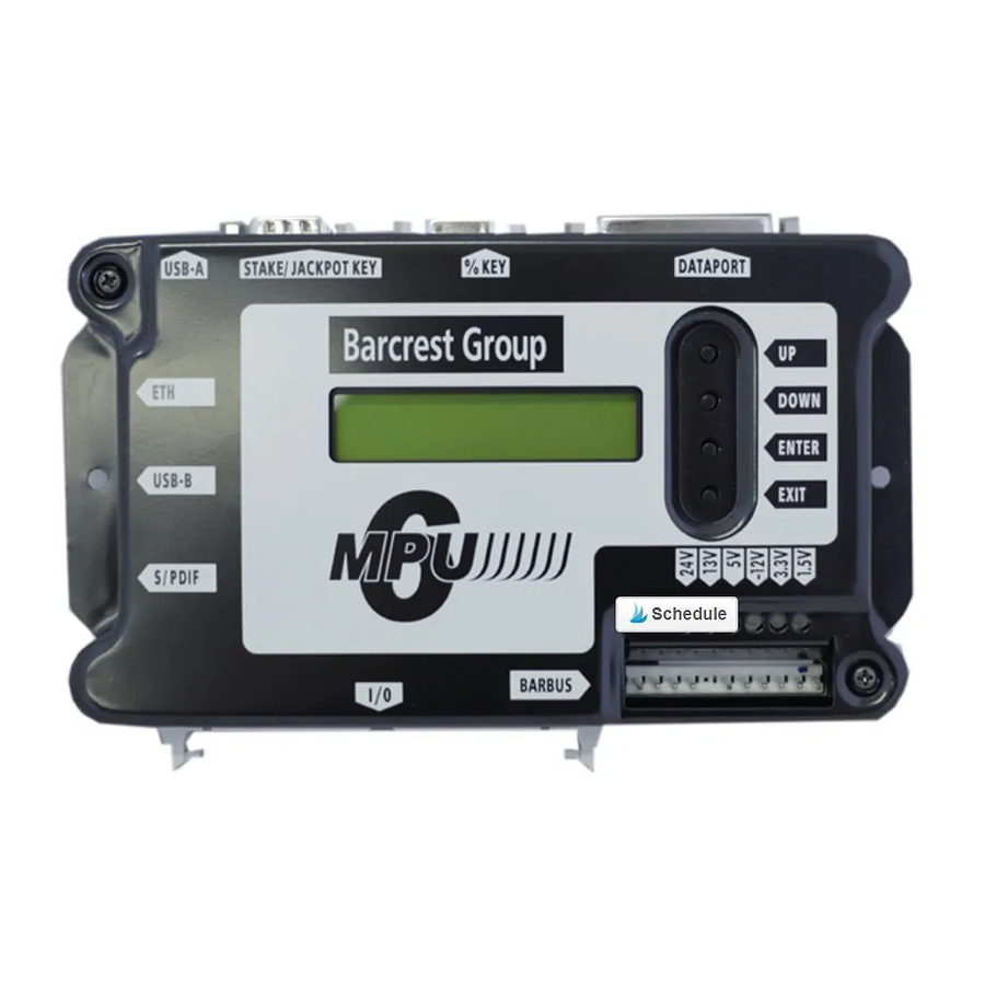
Page 23: Port Information
To interface to the outside world these connectors are mounted around the periphery of the unit, ensuring good mechanical support when plugging or unplugging thus minimising flexing of the PCB. The MPU6 board and its enclosure are fixed to the cabinet via two M4 screws. The MPU6 unit has the following connections & functionality. -
Page 24: Usb A Port
MPU6 board via a USB stick the following process should be followed. 3.3.1.2 Video Based Cabinets The USB A port allows the operator the facility to update the MPU6 board via a USB stick. MPU6 updates are normally performed during a PC executive update. Should the need arise to update the MPU6 outside of a PC executive update, for example changing from Data to Non Data the following process should be followed. -
Page 25: Usb B Port
3.3.1.3 RAM Clear In the event that the MPU6 requires a full clear down a USB stick is available from Barcrest Group spares and the following process must be followed. 1. Power down the machine. 2. Insert the USB “clear down” stick into USB port A. -
Page 26: Mpu6 Fault Codes
Class of alarm The various alarms, which can occur on the MPU6 system, are grouped into 15 classes. When a fault occurs, the first digit of the Barcrest Group alarm number shows the class of alarm A complete list of alarm messages, related to the associated BACTA and Barcrest Group fault code numbers are shown in the following sections. -
Page 27: Class 2 Alarms
USBDEV PORT FAIL 3.4.5 Class 3 alarms These are caused by faults on the MPU6 and relate to the flash memory. When shown on the display these alarms range from 31 - 36 with Bacta code 51 or 52. Bacta Code... -
Page 28: Class 4 Alarms
These alarms are the result of inconsistencies detected during software checks. These can be caused by software bugs or hardware problems with the memory. When shown on the display these alarms range from 41 – 4E with Bacta code 42, 48, 53 or Bacta Code Barcrest Group Message SOFTWARE CHECK... -
Page 29: Class 6 Alarms
These alarms are caused by coin input errors. When shown on the display these alarms range from 70 – 7F with Bacta code 10, 12, 13, 14, 81 or 82. Bacta Code Barcrest Group no Message Serial Coin Mech Coin Mech Jam Coin Mech Fail... -
Page 30: Class 9 Alarms
These alarms are caused by meter faults. When shown on the display these alarms range from 91, 92 and 95 to 98, with Bacta code of 61, 62 and 65 to 68. Bacta Code Barcrest Message Group No CASH IN METER... -
Page 31: Class D Alarms
3.4.14 Class D alarms Class D alarms relate to procedural events. When shown on the display these alarms range from D1 to D5, with Bacta code of 40, 41, 45 and 47. Bacta Code Barcrest Message Group No REFILL TURNED NEW OPTIONS... -
Page 32: Mpu6 Test Jig
These instructions are intended as a guide to enable independent testing of the MPU6 functionality. Before starting the test ensure that Bootstrap version 3.7 or greater is installed on the MPU6 or the functionality test cannot be completed. This can be checked by powering on the unit and then check the MPU6 Alpha Display. -
Page 33: Mpu6 Test Jig Main Components
Test Panel 3.5.4 Overview The functional testing of the MPU6 system board is carried out using a special purpose test jig to carry out testing of on-board interfaces, switches communications facilities including the central processor. The MPU6 is provided with its own internal test routine software to work specifically with the test panel to enable a functionality test. -
Page 34: Test Jig Set Up
1. Connect the USB lead between the USB A and B Ports. 2. Connect the D type test board to the Stake/Jackpot, Percentage and Dataport connectors 3. Connect the red Barbus power harness between the power supply and the MPU6 Barbus connector. -
Page 35: Boot Strap Version
To update the bootstrap, power down the MPU6 and then insert a USB stick. Now power up the MPU6 the file will now be read before going into the Erase and set up routines before finally the file has been verified. When this is complete the user is then prompted to remove the USB stick. -
Page 36: Test Routines
3.5.11 Individual Test To select individual tests scroll through the menu to run each individual tests on the MPU6. The “OPTIONS” menu allows loop back mode is turned on a test is repeated until it fails or EXIT is selected. -
Page 37: Test Serial Ports
3.5.14 TEST SERIAL PORTS This test the RTS, four FPGA serial ports, BARBUS and the DATAPORT. Each of these tests are as follows below and will indicate a pass or fail on test: • RTS PASS OR FAIL. • UART0 PASS OR FAIL •... -
Page 38: Test Usb
3.5.21 TEST USB This tests the USB A and B socket functionality. If the test passes then “USB PASS” is displayed, if it fails the “USB FAIL” is displayed. 3.5.22 TEST ETHERNET This test checks the Ethernet port functionality. 3.5.23 TEST RAM This tests the correct operation of the RAM chips. -
Page 39: Individual Test Selection
To select press the enter button and all of the test options will selected automatically in order. The MPU6 will indicate a pass or fail message as each test is completed. If a test fails then the MPU6 will show an alarm message related to the failed test. -
Page 40: Section 4 System Description
SECTION 4 SYSTEM DESCRIPTION The MPU6 system is a modular system comprising a number of key modules which in combination provide a flexible, reliable and economic solution for today’s gaming machine. The key modules are as follows: • MPU6 board. - Page 41 XXXX XXXX XXXX XXXX Alphanumeric display BARBUS Lamps Stake/ % Key Dataport MUX5(E) A Port J/pot BOARD USB B Port Speaker S/PDiff 64-way I/O Connector. For Switches and BARBUS Peripherals Supply Mode Power Supply Mains input Fig. 1 MPU6 system interconnections...
-
Page 42: Mpu6 Board
SEC Meter, USB A, B and for receiving inputs from switches. The MPU6 board is secured to the back of the cabinet either directly or on a bracket dependent on the machine type. This allows easy replacement of the MPU6 board when required. -
Page 43: Barbus
In addition to the power supplies routed to modules around the Barbus, +24V dc and -12V dc supplies are fed from the PSU directly to the MPU6 board only and do not form part of the Barbus daisy chain. - Page 44 SLAVES MPU6 LONG PIN COMMS- KEY WAY COMMS+ -12V Barbus Interface Fig. 2 Barbus interconnection and addressing...
-
Page 45: I.d.c Connectors
The colour of the nylon housing indicates for which gauge of wire the “U” groove is designed. In the case of MPU6 systems most wires are 7/02 and therefore most of the I.D.C. housings are coloured white. 4.6.1 Identification The in-line I.D.C. - Page 46 Rear View of a Top or Bottom Glass Typical Lampholder Other Lampholders Green Wire Blue Wire Diode Within Other Lampholders Lampholder Wires Green To Other Lamp To Other Selects Lamp Drives Blue Wires Blue Wires Green Wires 17-Way Green I.D.C. Connector To MUX5/MUX5E Board Fig.
-
Page 47: Metering
• The host machine controls the display of the various meters and text to explain which meter is being shown. • The electronic meter uses the existing mechanical “Meters” port on the MPU6 to interface to the machine. • The SEC interfaces to the host machine using secure protocol to reduce the risk of tampering. -
Page 48: Switch Mode Power Supply
The long-term accountancy and service history meters can be cleared only at the factory or by the use of a Clear Down USB stick to erase the contents of the MPU6 non-volatile memory. Instructions for using stick key are given in Sect 3.3.1.3 4.7.5 Data access... -
Page 49: Switch Mode Power Supply Outputs
4.8.2 Switch Mode Power supply outputs The power supplies provided by the unit are as shown below. SUPPLY +34V dc Multiplexed lamp supply, Payout port, Vend-bus. +12V dc Supply for +5V regulators, for reel stepper motors, Dataport, Alpha displays, Meters and Coins mech. -12V dc Dataport and Sound 24V dc... -
Page 50: Reel Assembly
4.9 Reel Assembly 4.9.1 General The machines are generally fitted with the Gamesman and Starpoint types of reel assembly. 4.9.2 Gamesman assembly The Gamesman reel assembly is a single unit comprising a blue injection-moulded frame carrying a stepper motor, reel drum, light box and opto, The stepper motor is fitted to the frame by means of an adjustable mounting ring and the light box mounting has sufficient adjustment to allow use of the reel in the Horizon or Rio machines without having to change the reel position. -
Page 51: Reel Drum
LED source to a photocell, and is referred to as the interrupter flag. When the machine is first switched on the reels spin at least two revolutions for the MPU6 to determine the exact reel position and check serviceability. -
Page 52: Photo Components
4.9.10 Reel bands Reel bands for the MPU6 may have 12, 16 or 24 symbols and may be of a wide or narrow type. The required number of “stops” is determined by the MPU6 program and makes no difference to the rest of the reel assembly. -
Page 53: Reel Assembly Fixing
The bands are designed to be easily removed and refitted without re-alignment being necessary. Each band is securely located beneath the rim on each side of the drum. Two pegs retain the band to secure and ensure correct alignment and prevent any slipping. The transparent leader at the start of each band is printed with machine identification and part number. -
Page 54: Sec Meter
4.11 Dataport interface To enable the MPU6 to be easily and securely interfaced to a Datapak, which may be specified to back up the electronic metering and provide a downloadable machine event store, an industry standard Dataport is fitted. -
Page 55: Sp/Diff (Audio)
The proprietary Barbus is a combined power bus and serial data link connected in a daisy chain layout between the machine modules as shown in Figure 2. The Barbus is connected to the MPU6 board via a red 11-way BARBUS connector as shown in Fig. 24, the connector having a keyway at pin position 7. -
Page 56: Mux5 And Mux5E Boards
Most gaming machines use more lamps, LEDs and illuminated push buttons than can be controlled directly by the MPU6 board. The MUX5 board block diagram is shown in Fig. 28 and provides the MPU6 system with the ability to control additional devices. The MUX5E is similar to the MUX5 in design, but provides an additional 64 lamps. - Page 57 Fig. 28. MUX5 board block diagram...
-
Page 58: Buttons Interface
4.19 Buttons interface The MUX5(E) board can interface with 16 illuminated pushbuttons via a brown 13-way BUTTONS connector having a keyway at pin position 11. The interface's lamps and switches are each wired into a 2 x 8 matrix as shown in Fig. 29. The diode in the switch input line protects the transistor against +34V which might appear on the line under certain fault conditions. -
Page 59: Barbus Interface
4.20 Barbus interface The Barbus interface shown in Fig. 30. is based on the MPU6 board and is connected to the MUX5 board via a red 11-way BARBUS connector having a keyway at pin position 7. The Barbus provides a +34V supply for lamps and a +12V supply for electronics; these supplies are protected by on-board fuses. -
Page 60: Led Displays
4.21 LED displays The MUX5 board can drive up to eight LED displays, each comprising seven segments plus a decimal point. 4.22 Alphanumeric display Provision to drive an Alphanumeric Display is made through a black 7-way ALPHA connector on the MUX5(E) board, having a keyway at pin position 5. A simple jumper harness links through to a connector on the display PCB. -
Page 61: Mux5(E) Fuses
If the sequence is not obtained, check that the +12V LED is lit on the MPU6 board if not then the fault is likely to be the Power supply unit. -
Page 62: Reel5 Control Board
MPU6 board. An 8-bit on-board processor (cpu) controls each reel independently, receiving reel positioning requirements from the MPU6 board via the Barbus serial data link and generating position demands via 8-bit parallel ports. Each reel is controlled via three interfaces. The reel stepper motor is driven via a REEL... -
Page 63: Reel Interface – Starpoint And Gamesman
Fig 32. The connector has a keyway at pin position 9. When the MPU6 processor requires a reel to change position it transmits data to the REEL5 control board via the Barbus serial link. The REEL5 CPU produces a 4-bit pattern of pulses from the relevant parallel port, these pulses are amplified by current drivers and are output to the reel motor to drive the reel to the required position. -
Page 64: Reel Lamp Interface – Starpoint And Gamesman Reels
4.24.2 REEL Lamp Interface – Starpoint and Gamesman Reels The lamp matrix is a 5 x 3 matrix comprising five reels each having three lamps, and is connected to the REEL5 board via a red 15-way connector having a keyway at pin position 9. The typical lamp drive and select circuit shown in Fig. -
Page 65: Opto Interface Gamesman Reels
4.24.3 OPTO interface Gamesman Reels The OPTO interface, shown in Fig. 34, allows the on-board cpu to determine the reel position. An infra-red LED and associated photo transistor are mounted on an OPTO pcb fitted to the reel frame. An opto tab is fitted to the reel drum and interrupts the light source once per revolution of the reel to produce a low pulse from the transistor emitter. -
Page 66: Strobe Signals
4.24.4 STROBE Signals The strobe signals STROBE1 and STROBE2 are provided for games which require a strobe light to flash, synchronised to the reel steps so as to provide animation as seen by the player. For machines using strobe signals, these are output via a 6-way STROBE connector having a keyway at pin position 3. -
Page 67: Polyfuses
4.24.10 Polyfuses On board polyfuses are provided for the +12V, +24V, -12V and +34V supplies to protect the MPU6 circuit. 4.24.11 Status LEDs For each of the +12V, –12V, +24V and +34V board supply rails a green LED glows to show a... -
Page 68: Mpu6 Board Replacement
5.1.3 MPU6 Refitting Place the MPU6 in position over the mounting holes and screw the two mounting screws to secure it place. Now replace each of the previously removed connectors in their correct... -
Page 69: Mpu6 I/O
5.2 MPU6 I/O The I/O for the MPU6 connections is given in the sections below. 5.2.1 Speaker Connections Pin Function Speaker Left Negative Speaker Left Positive Speaker Right Negative Speaker Right Positive 5.2.2 Switch Connections (First MPU6 Horizon only) Function... -
Page 70: Ardac Note (Acceptor Netplex)
5.2.5 Ardac Note (Acceptor Netplex) Function Ground 5.2.6 Coin Mech Function Ground CCtalk 5.2.7 Meters Function Ground Meter Reset Data Out Meter Sense Meter CLK 5.2.8 Dallas Key (Triple 7 only) Function Hopper Dump Ground Test Top Up Refill... -
Page 71: Dallas Key (Uk Horizon Only)
5.2.10 Fan Sense (Triple 7 Only) Function Fan Sense Fan Sense Fan Sense 5.2.11 MPU6 Configuration IButton Cell (Horizon Only) The horizon machine is fitted with an IButton cell that stores the machines configuration information that includes the following: • Hopper Balance • IButton Information •... -
Page 72: Mux5 And Mux5E Board Replacement
5.3 MUX5 and MUX5E Board replacement Switch off the mains power to the machine and disconnect the mains plug from the power point. Gain access to the interior of the machine as described in the specific Machine Manual. 5.3.1 Connector locations The location of all connectors on the MUX5 board is shown in Fig. - Page 73 Fig. 37 MUX5 board connector layout...
- Page 74 GREEN LAMPS1 GREEN LAMPS2 BLUE LAMPS3 BROWN BLACK BUTTONS ALPHA LAMPS4 Fig. 38. MUX5E board connector layout...
-
Page 75: Mux5(E) Pin Listings
5.3.4 MUX5(e) Pin listings LAMPS1, LAMPS2 (in parallel) Signal Function Signal Function LAMP_HIGH_0 Drive line LOW_SIDE_0 Select line LAMP_HIGH_1 LOW_SIDE_1 LAMP_HIGH_2 LOW_SIDE_2 LAMP_HIGH_3 LOW_SIDE_3 LAMP_HIGH_4 LOW_SIDE_4 LAMP_HIGH_5 LOW_SIDE_5 Keyway LOW_SIDE_6 LAMP_HIGH_6 Drive line LOW_SIDE_7 LAMP_HIGH_7 LAMPS3 connector Signal Function Signal Function LAMP_HIGH_8 Drive line... - Page 76 LEDS connector Signal Function Signal Function LOW_SIDE_7 Select line LED_HIGH_G Drive line LOW_SIDE_6 LED_HIGH_F LOW_SIDE_5 LED_HIGH_E LOW_SIDE_4 Keyway LOW_SIDE_3 LED_HIGH_D Drive line LOW_SIDE_2 LED_HIGH_C LOW_SIDE_1 LED_HIGH_B LOW_SIDE_0 LED_HIGH_A LED_HIGH_DP Drive line BUTTONS connector Signal Function Signal Function BUT_SW_0 Switch I/P LOW_SIDE_5 Select line BUT_SW_1...
-
Page 77: Reel5 Control Board Replacement
5.4 REEL5 control board replacement This type of PCB was used on the earlier versions of MPU5 machines fitted with Barcrest Group reel assemblies. Switch off the mains power to the machine and disconnect the mains plug from the power point. -
Page 78: Connector Locations
5.4.4 Connector locations The location of all connectors on the REEL5 control board is shown in Fig. 39. Fig. 39 REEL5 control board connector layout... -
Page 79: Reel5 Pcb Pinout
5.4.5 REEL5 PCB Pinout REEL1 to REEL5 connectors Signal Function Signal Function +12V +12V +5V (OPTO) REELn-2 Motor drive Ground (0V) REELn-4 LOW1 Select Line REELn-3 LOW2 REELn-1 LOW3 Keyway HIGHn * Lamp Driver HIGHn * Lamp Driver * n = 1 to 5 for reels 1 to 5 respectively STROBE connector Signal Function... -
Page 80: Power Supply Replacement
5.5 Power supply replacement Switch off the mains power to the machine and disconnect the mains plug from the power point. Gain access to the lower compartment of the machine interior as described in the specific Machine Manual. 5.5.1 Removal •... -
Page 81: Reel Assembly (Gamesman) Repair
5.6 Reel assembly (Gamesman) repair 5.6.1 Lamp replacement • Squeeze the two retaining lugs on the relevant lampholder and withdraw the lampholder from the lightbox. • Pull the unserviceable lamp from the lampholder and push a new lamp (12V, 2.2W, wedge base) into position. -
Page 82: Lightbox Replacement
5.6.6 Lightbox Replacement • Remove the reel drum as described in Sect. 5.6.2. • Note the position of the lightbox position marker against the –90 to +90 scale on the frame. • Note the position of all lampholders relative to each other and to the lightbox. •... -
Page 83: Lightbox Repairs
5.7 Lightbox repairs Switch off mains power to the machine and disconnect the mains plug from the power point. Gain access to the interior of the machine as described in the specific Machine Manual. 5.7.1 Lamp replacement • On the standard lamp holder as fitted to a light box, depress the plastic lug, then withdraw the lamp holder from the lightbox. -
Page 84: Section 6: Ibutton Functionality And Registration
At this point the hopper will be topped up to its maximum float capacity. To enter the test routine using the IButton, press the MPU6 enter button and the LCD will display a “Confirm Test Mode” message. -
Page 85: Refill Mode Switch
6.1.3 Refill Mode Switch. The refill IButton has the facility to offer different levels of access to the Horizon cabinets refill menu. The refill receptor is located in the same position as the refill switch used on the MPU5 Horizon cabinet to the left of the payout tray. To enter refill present the IButton to the Refill receptor. -
Page 86: Hopper Dump Switch
Within each machines fitted near the note acceptor harness connector is a shrouded PCB that contains an IButton cell that stores the following machine information. This is to ensure that the machines settings are retained in the event of having to replace the MPU6 unit. • Hopper Float •... -
Page 87: Section 7 Coin Handling Equipment
SECTION 7 COIN HANDLING EQUIPMENT 7.1 Dual Hopper Shelf The MPU6 Horizon dual hopper assembly is capable of housing an extra hopper as required. Please note that the MPU6 SCH3 hopper bed assembly is not compatible with the MPU5 SCH2 MKII serial hopper, as used on all previous MPU5 Horizon products. -
Page 88: Dual Hopper Shelf Disassembly
7.1.2 Dual hopper Shelf Disassembly The hopper assembly can now be disassembled to gain access to the hopper assembly, unclip the six clips that clamp the assembly together as indicated in the following three images below. There are two clips on each side of the hopper as indicated in figures 49 and 50 below. Fig 49 Fig 50 Unclip the remaining two clips from the rear of the hopper as indicted in figure 51 below and... -
Page 89: Hopper Bed Removal And Replacement
7.1.3 Hopper Bed Removal and Replacement Figure 52 below shows how the hopper base is removed from the hopper bed assembly casing. The black arrow indicates the direction the release tab needs to be pressed to allow removal of the hopper from the housing. In Figure 53 the sides of the hopper are prised apart with the thumbs pushing away from the centre as indicated. -
Page 90: Coin Mechanism Replacement
7.2 Coin Mechanism replacement The MPU6 horizon machine is fitted with a SR5I coin mech that has been set to encryption mode. The replacement if required needs to be set to this mode as mechs used on the MPU5 Horizon are not compatible. -
Page 91: Removal
7.2.3 Removal • At the coin mechanism, disconnect the I.D.C. connector or the 10-way CCtalk connector as necessary from the machine harness. • At the rear of the coin mechanism bracket, push the white latch to the rear and lift the bottom of the mechanism, swing the bottom outwards and slide the top out from the machine. -
Page 92: Section 8: Horizon Mpu6 Programming And Clock Setting
SECTION 8: HORIZON MPU6 PROGRAMMING AND CLOCK SETTING. 8.1 MPU6 Programming instructions The MPU6 is provided with a USB A port to allow service engineers to upgrade game software on site using a USB Stick without the need to carry compact flash cards or proms. -
Page 93: Mpu6 Real Time Clock Set Up
8.2 MPU6 Real Time Clock set up To comply with the regulations enforced on the 1 of September 2007 it is necessary to have a real time clock facility. This section details the instructions required to set the real time clock (RTC).
Need help?
Do you have a question about the MPU6 and is the answer not in the manual?
Questions and answers