Advertisement
Eltek TU 1004 User Instructions for RC250 receiver
Packed items
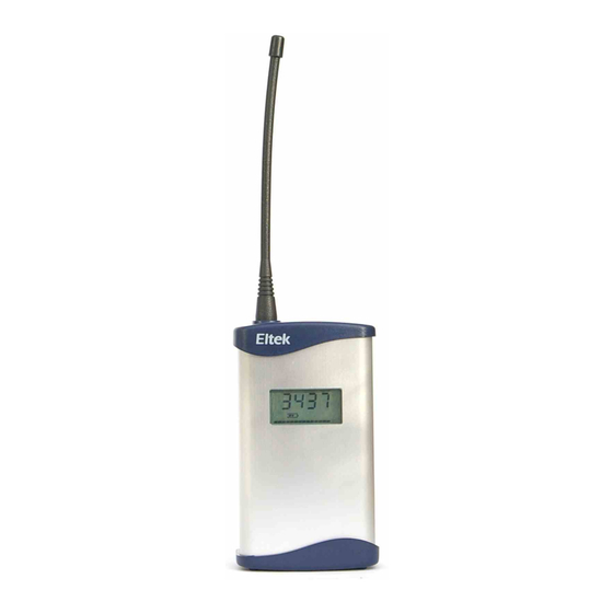
RC250 receiver with serial and Modbus output
"
Antenna (basic whip) – Eltek type UHFFlexi/SMA
"
MP12U5W power supply with regional adaptor
"
LC68 – RC250 to PC serial lead
"
USB to serial converter lead
"
LCTX3 – Transmitter to PC serial lead
"
RxConfig software
"
RxConfig software
RxConfig can also be downloaded from: www.eltekdataloggers.co.uk
When installed, RxConfig creates a folder "Eltek". In this folder are the
RC250 documents for details of Modbus over serial, etc. for Modbus
limitations.
The program allows the user to:-
Read transmitter settings
"
Set the transmitter interval
"
Associate an RC250 Channel with a specific transmitter channel
"
Meter configured RC250 channels
"
Operation
The RC250 works by first receiving a data 'packet' from a transmitter, verifying it, then
storing it to be read by the external device or PC. It is verified by means of a checksum
contained in the message and the associated transmitter number.
If the RC250 does not receive a message from a transmitter within a configured time, the
stored value will be set to "no data". For more detail see P6 "No Data interval".
Example application: Typically data from the RC250 to the PC is updated every 30
minutes, so the transmitter interval is set to 5 minutes (that this PC update period ÷ 6)
and the "No Data" interval to 2 hours. (that is PC update period x 4). If the transmitter
stops transmitting for any reason the PC should register this fact after 2 hours.
Power Requirements
The RC250 requires permanent AC mains connection. Use only the AC power supply type
MP12U or the provided MP12U5W. Built-in Ni-Mh batteries provide up to 3 days standby
in the event of power failure. A fully discharged battery is charged in 72 hours. Once the
batteries become low the RC250 will switch itself into a low power mode and turn off the
OFF
receiver.
will appear in the display.
Note: the RC250 is despatched in the
The RC250 will power up (turn on) next time external power is applied. The display will
then switch to working mode. The RC250 can be turned off by removing the external
power and then clicking
switch accessed through the case rear.
OFF
mode.
Tools
Turn Receiver Off
>
or briefly pressing the concealed
Page 1 of 8
Advertisement
Table of Contents

Related Manuals for Eltek TU 1004

Summary of Contents for Eltek TU 1004
-
Page 1: Power Requirements
" RxConfig software RxConfig can also be downloaded from: www.eltekdataloggers.co.uk When installed, RxConfig creates a folder “Eltek”. In this folder are the RC250 documents for details of Modbus over serial, etc. for Modbus limitations. The program allows the user to:- Read transmitter settings "... - Page 2 Application For users who wish to use the Eltek GenII series of transmitters with third party or proprietary software. The RC250 can also be used to interface GenII transmitters to an existing data acquisition system such as the Datataker DT80 using Modbus.
- Page 3 Using Receiver Config - From V1.1 Load the program on your PC – it will try to find an existing Eltek folder. To program the RC250 use the LC68 lead. Connect one end to the serial port of the PC and the other to the mini DIN socket situated on the top panel of the RC250.
- Page 4 Channel Set-up Procedure Transmitter present: Start up the Configuration program. (If this is the first time it has run you will need " to configure the serial port(s) using File > Properties Connect the PC to the RC250 using the LC68 programming lead (and USB "...
- Page 5 Columns in the RX Configuration panel table: Chan This is the RX250 channel allocated (1 - 160 max) Tx Chan This is the TX channel allocation and is always an alpha character typically A to H Tx Range TX Chan range e.g. Humidity SHT if the B channel of a GD10 Value Tx Value of last valid data received expressed in units allocated to the range.
-
Page 6: Modbus Configuration
Modbus configuration The ModBus Setup menu allows the configuration of the ModBus node address and channel registers. Node Address should be set to the required 'Slave ID'. The following six boxes are for specifying addresses of holding registers for reporting the transmitter information. - Page 7 Example response from RC250: Slave Address Function Byte count Raw Val Hi Raw Val Lo 2b (in decimal, 1579) CRC Hi CRC Lo Example request to retrieve holding register 200-201 (set up to contain the scaled values from channels 1 and 2) from node address 6: Slave Address Function Starting Address Hi...
-
Page 8: Serial Data
Data Bits Stop Bits Parity None Product Specification Maximum no. Channels AC supply 100 to 250V AC (Use only Eltek power supply type MP12U / MP12U5W) DC input 12VDC Maximum current <150mA Battery endurance Up to 72 hours Controls Concealed button (power off) Freq.
Need help?
Do you have a question about the TU 1004 and is the answer not in the manual?
Questions and answers