Table of Contents
Advertisement
CRC
Manual Stock No. 9250-0122
OWNER'S MANUAL
Capintec, Inc.
Sales and Marketing
and Customer Support
6 Arrow Road
Ramsey, NJ 07446
Phone (800) ASK-4CRC
Fax (201) 825-1336
Capintec, Inc.
Only Authorized Service Center
620 Alpha Drive
Pittsburgh, PA 15238
Phone (800) 227-6832
Fax (412) 963-0610
©
Copyright
®
CRC is a registered trademark of Capintec, Inc.
ALL RIGHTS RESERVED
An Eczacɩbaşɩ-Monrol company
®
-25R
2006 Capintec, Inc.
Rev. H – March 2015
Advertisement
Table of Contents

Subscribe to Our Youtube Channel
Summary of Contents for Capintec CRC-25R
- Page 1 Fax (201) 825-1336 Capintec, Inc. Only Authorized Service Center 620 Alpha Drive Pittsburgh, PA 15238 Phone (800) 227-6832 Fax (412) 963-0610 © Copyright 2006 Capintec, Inc. ® CRC is a registered trademark of Capintec, Inc. ALL RIGHTS RESERVED An Eczacɩbaşɩ-Monrol company...
-
Page 3: Table Of Contents
® CAPINTEC, INC. -25R TABLE OF CONTENTS PREFACE SAFETY ..........................1-1 SYMBOL DEFINITIONS ....................1-1 WARNING AND CAUTION LABELS ................1-2 CAUTIONS AND NOTES ....................1-3 GENERAL SAFETY TIPS ....................1-6 FUNCTIONAL & TECHNICAL DESCRIPTION ..............2-1 INTENDED USE ......................2-1 OPERATOR PROFILE.................... - Page 4 ® CAPINTEC, INC. -25R SOURCES Key ....................... 3-2 NUCL Key ....................... 3-2 CAL# Key ........................ 3-2 TIME Key ........................ 3-2 TEST Key ........................ 3-2 BKG Key ......................... 3-2 HOME Key ......................3-3 MENU Key ......................3-3 Ci / Bq Key ......................3-3 CE Key ........................
- Page 5 ® CAPINTEC, INC. -25R Screen Saver ......................5-18 Screen Contrast ......................5-19 CHAMBER INITIALIZATION ..................... 6-1 GENERAL........................6-1 USER KEY ASSIGNMENT ..................... 6-1 Selecting User Key ...................... 6-2 Current Assignment Display ..................6-2 Nuclide Name Assignment ..................6-3 Assignment Confirmation .................... 6-3 TEST SOURCES ......................
- Page 6 ® CAPINTEC, INC. -25R Linearity Test ....................... 7-2 DAILY QUALITY ASSURANCE TESTS ................7-2 Daily Tests ........................7-2 Accuracy Test ......................7-2 Contamination Test ...................... 7-3 QUARTERLY TESTS ...................... 7-4 Diagnostic Test ......................7-4 YEARLY TESTS ......................7-4 Linearity Test ....................... 7-4 BACKGROUND AND TESTS .....................
- Page 7 ® CAPINTEC, INC. -25R MOLY ASSAY ......................10-10 Mo99 Background ....................10-11 Mo99 Assay ......................10-13 Tc99m Assay ......................10-14 Moly Assay Results ....................10-14 ENHANCED TESTS......................11-1 GENERAL........................11-1 ENHANCED TESTS MENU ..................11-1 GEOMETRY TEST ....................... 11-2 Measuring with Syringe ..................... 11-2 Measuring with Vial ....................
- Page 8 ® CAPINTEC, INC. -25R CLEANING AND MAINTENANCE ................... 15-1 GENERAL ........................15-1 CLEANING and DISINFECTING ................... 15-1 Cleaning Instructions ....................15-1 Readout Unit and Chamber ................... 15-1 Liner/Dipper ......................15-2 Printer........................15-2 Remote Display ..................... 15-2 Disinfecting Instructions ..................... 15-2 Liner/Dipper ......................
-
Page 9: Preface
Capintec, Inc. assumes no responsibility for the results of errors beyond its control. Mention of products manufactured by other companies does not necessarily constitute endorsement by Capintec, Inc. - Page 10 Increase the separation between the equipment and the affected device. • Plug the unit into an outlet on a circuit different from that which the affected device is connected. If this fails to correct the problem, please contact Capintec’s only Authorized Service Center. p - 2 PREFACE February 15...
- Page 11 ® CAPINTEC, INC. -25R IMPORTANT SAFETY INFORMATION ® The CRC -25R measurement system has been carefully designed to provide years of safe and reliable performance. As with all electrical equipment, however, there are basic precautions that must be observed to avoid injuring yourself, the patient or damaging the equipment.
- Page 12 ® CAPINTEC, INC. -25R This page intentionally left blank.
-
Page 13: Safety
® CAPINTEC, INC. -25R CHAPTER 1 SAFETY ® These warnings and instructions for use form an integral part of the CRC -25R and must therefore be kept available for consultation at all times. Precise compliance with the instructions is an essential condition for normal use, correct application and thus safety of the user. -
Page 14: Warning And Caution Labels
® CAPINTEC, INC. -25R WARNING AND CAUTION LABELS Located on the back of the Readout Unit is a label, (Figure 1-1), providing the system power requirements and the replacement fuse values for power line voltages. CAUTION: Please reference CHAPTER 15: CLEANING AND MAINTENANCE, SECTION: FUSE SERVICING for instructions on how to change the ®... -
Page 15: Cautions And Notes
-25R is not designed to use syringe Test Sources in any application. CAUTION: Capintec, Inc. does not provide the calibration number for any type of Brachytherapy source. The user should have the source calibrated by a regional Accredited Dosimetry Calibration Laboratory (ADCL) site or... - Page 16 Canister) always lower it gently into the Chamber. Dropping any heavy object into the Chamber can cause permanent, expensive damage. CAUTION: The use of multiplication and division factors in Calibration Numbers is only to maintain a degree of consistency with other Capintec Dose ® Calibrators. The CRC -25R is a direct reading instrument.
- Page 17 Electromagnetic Interference (EMI) to nearby devices. However, there is no guarantee that interference will not occur in a particular installation. CAUTION: If any printer other than one of the models supplied by Capintec is used, the safety of the unit may be compromised or Electromagnetic Interference (EMI) may be introduced into other devices located in the ®...
-
Page 18: General Safety Tips
® CAPINTEC, INC. -25R GENERAL SAFETY TIPS Unplug the equipment before cleaning it. Use only a damp cloth; do not use solvents or aerosol cleaners. To protect the equipment from overheating, do not use the equipment directly in front of a radiator or heat register. -
Page 19: Functional & Technical Description
® CAPINTEC, INC. -25R CHAPTER 2 FUNCTIONAL & TECHNICAL DESCRIPTION INTENDED USE ® The CRC -25R is intended to be used by trained Nuclear Medicine Technologists and Physicians, for measuring the activity of a radioisotope samples for Nuclear Medicine and Brachytherapy. -
Page 20: Functional Description
® CAPINTEC, INC. -25R FUNCTIONAL DESCRIPTION ® The CRC -25R provides a precise, accurate, fast and very convenient method of measuring the activity of a radioisotope sample for Nuclear Medicine and Brachytherapy. The activity of the sample will be displayed with a proper unit when a sample of unknown strength (activity) of a known radioisotope is placed in the ionization chamber and the correct calibration number is selected. -
Page 21: Overall Program Flow
® CAPINTEC, INC. -25R OVERALL PROGRAM FLOW When the power is turned on, the Sign-On Screen appears. When the ENTER key is ® pressed, the Measurement Screen is displayed and the CRC -25R begins measuring the activity. All measurements, the Main Menu and the Test Menu are accessed from this screen. -
Page 22: Technical Description
® CAPINTEC, INC. -25R TECHNICAL DESCRIPTION On / Off Switch The on/off switch (I = on; = off) is located on the back of the instrument. Warm Up Period Approximately 30 minutes should be allowed for the instrument to stabilize. While the instrument is warming up, it is strongly recommended that you become familiar with the ®... -
Page 23: Power Requirements
® CAPINTEC, INC. -25R Power Requirements CAUTION: If the input voltage to the following items is not within the stated limits, the unit may not function correctly or may be damaged Line Voltage Readout 100-240Vac, 50/60Hz, 245mA Printers Okidata Microline 320 (optional) 120Vac, 60Hz, 0.9A or... -
Page 24: Dimensions
® CAPINTEC, INC. -25R Dimensions Console Height ......13.7cm ..(5.38in) Width ......26.0cm ..(10.25in) Depth ......26.7cm ..(10.5in) Weight ....... 1.8kg ..(3.9lb) Chamber Height ......43.8cm ..(17.25in) Diameter ....17.2cm ..(6.76in) Weight ....... 13.6kg ..(30lb) Well Diameter .... -
Page 25: Regulatory Listings
® CAPINTEC, INC. -25R Regulatory Listings ® The CRC -25R has been independently tested and is manufactured in compliance with the following Standards: • IEC 61326: Electrical equipment for measurement control and laboratory use – EMC requirements Electrical • EN 61010-1: Safety requirements for electrical equipment for measurement,... - Page 26 ® CAPINTEC, INC. -25R This page intentionally left blank.
-
Page 27: General Operating Instructions
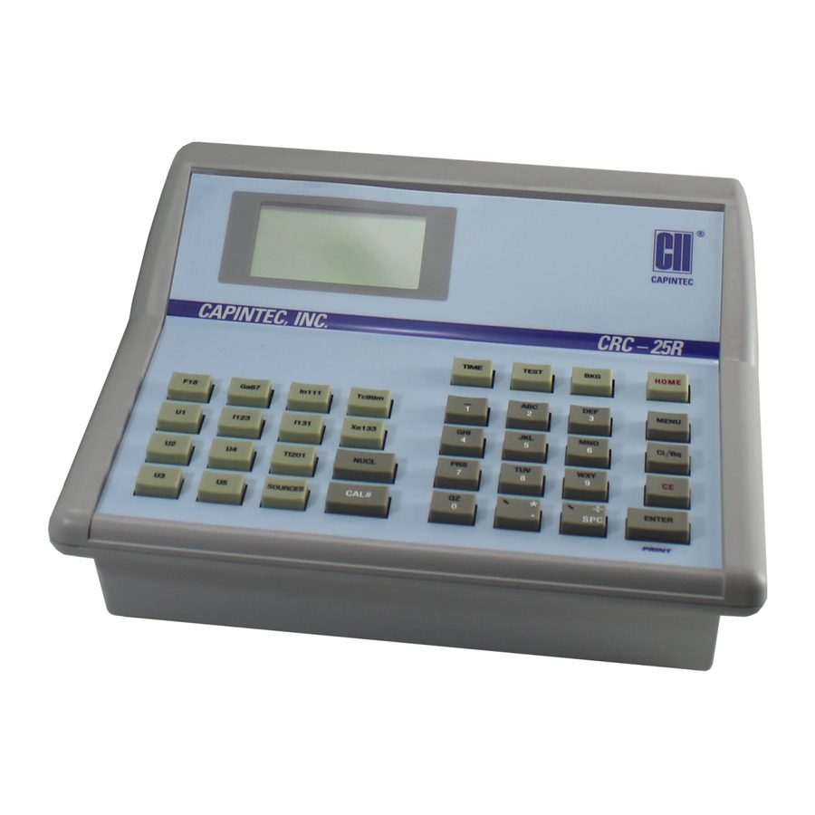
® CAPINTEC, INC -25R CHAPTER 3 GENERAL OPERATING INSTRUCTIONS GENERAL This section describes general operating procedures: the keyboard, how to enter data and make menu selections. KEYBOARD Layout ® -25R keyboard is shown below. Figure 3-1 Keyboard July 07 GENERAL OPERATING INSTRUCTIONS... -
Page 28: Key Usage
® CAPINTEC, INC -25R Key Usage General usage of keys is briefly described. Specific key usage will be given in the appropriate sections. NUCLIDE Keys Pressing one of these keys selects that nuclide. F18, Ga67, In111, Tc99m, I 123, I 131, Xe133, Tl201 USER Keys Any nuclide in memory may be assigned to any of the USER Keys. -
Page 29: Home Key
® CAPINTEC, INC -25R HOME Key Pressing this key will return the user to the Measurement Screen. If this key is pressed before ending the task being performed, the task will be terminated without being finished (e.g. entered data will not be stored and previous values are maintained). -
Page 30: Entering Data
® CAPINTEC, INC -25R ENTERING DATA Numeric Data Numeric data is entered via the NUMBER / LETTER keys on the right hand side of the keyboard. The decimal point is on the same key as the UP ARROW ( ). -
Page 31: System Setup
Should the instrument be received in a damaged condition, save the shipping container and the packing material and request an immediate inspection by the carrier. Capintec, Inc. is not responsible for the damage, which occurs during shipment but will make every effort to help obtain restitution from the carrier. -
Page 32: Assembly
® CAPINTEC, INC. -25R o Epson Stylus C86 Inkjet (or equivalent) printer The Printer should have the following accessories: • Power Supply • Printer Ribbon • Communications Cable • Roll Paper (If Roll printer ordered) • Tickets (If Ticket printer ordered) Note: If Test Sources are ordered, they will be shipped separately. - Page 33 ® CAPINTEC, INC. -25R Note: To avoid damage, do not over-tighten the screws on the Cable connectors. The screws should be finger-tightened only! 3. Attach the Power Cable to the receptacle on the Power Module located on the back of the Readout Unit.
-
Page 34: Liners, Dippers, Optional Dipper And Holders
Test sources (Standard Sources). For all other source measurements, use the appropriate source holder for the source type being measured in order to obtain a correct reading. If additional information is needed, contact Capintec, Inc. for further assistance. 4 - 4 SYSTEM SETUP... -
Page 35: Environment Requirements
® CAPINTEC, INC. -25R ENVIRONMENT REQUIREMENTS Indoor use only. Pollution Degree 2, Altitude, and Installation Cat. II. The instrument should be located where the level of the background radiation is as low and as constant as possible. The instrument should be located where the temperature is stable within a range of +50°F to +85°F (+10°C to +30°C) and the maximum relative humidity is 90% non-condensing to... -
Page 36: Turn On Procedures
-25R Rev X.XX COPYRIGHT 2006 ALL RIGHTS RESERVED CAPINTEC, INC. NJ USA ENTER to Continue Figure 4-5 Note: The screen will display the revision level of the installed software. GENERAL OPERATIONAL SETUP ®... - Page 37 ® CAPINTEC, INC. -25R or Ra226. There can be a Test Source for each of these nuclides. One or more of the Test Sources must be designated as the source(s) to be used in the Daily Test. Reference CHAPTER 6: CHAMBER INITIALIZATION, SECTION: TEST SOURCES.
-
Page 38: Acceptance Testing
® CAPINTEC, INC. -25R ACCEPTANCE TESTING The following tests should be performed prior to operational use of the unit. Chamber Tests Diagnostics Test Reference CHAPTER 9: DIAGNOSTICS for instructions on how to perform this test. Daily Test Reference CHAPTER 8: BACKGROUND AND TESTS, SECTION: DAILY TEST for instructions on how to perform this test. -
Page 39: System Initialization
® CAPINTEC, INC. -25R CHAPTER 5 SYSTEM INITIALIZATION GENERAL This section describes initialization and parameter setup. All of these functions are accessed via the Main Menu. Press MENU from the Measurement Screen. The Main Menu will appear. 1. Inventory 2. Calculations 3. - Page 40 ® CAPINTEC, INC. -25R Apr 04 2006 09:56 Correct ? Yes or No Figure 5-3 Date / Time Verification Screen If the date and time are correct, press YES. Figure 5-2 Main Setup Menu will re-appear. If the date and/or time are incorrect, press NO to make necessary changes. Figure 5-4 Date Entry Screen will appear.
-
Page 41: Choosing Ci Or Bq
® CAPINTEC, INC. -25R Figure 5-3 Date / Time Verification Screen will be shown. Press YES if it is correct. Figure 5- 2 Main Setup Menu will re-appear. Press NO to make corrections. CHOOSING Ci or Bq Measurement results can be displayed in Ci or Bq. The Ci/Bq key is used to switch the measurement result between Ci and Bq. -
Page 42: Printing
If the displayed setting is not correct, press NO. Figure 5-7 Ci / Bq Selection Screen will re- appear. PRINTING CAUTION: If any printer other than one of the models supplied by Capintec is used, Electromagnetic Interference (EMI) may be introduced into other devices ®... -
Page 43: Printer Selection
® CAPINTEC, INC. -25R Epson Stylus C86 Inkjet (or equivalent) printer (optional) 100-240Vac, 50/60Hz, 0.4A Printer Selection ® If a printer was included with the CRC -25R, the system will already be set to use the included printer. If a printer is being added or the system did not include a printer at the time ®... -
Page 44: Rs-232
® CAPINTEC, INC. -25R RS-232 RS-232 printers are serial printers that use the RS-232 interface. The printers that ® can be used with the CRC -25R are the Epson Slip, Epson Roll, Okidata Microline 320 or Epson LX-300. From Figure 5-9 Printer Type Screen, select RS-232. Figure 5-10 RS-232 Printer... - Page 45 ® CAPINTEC, INC. -25R PRINTER IS ONE LINE Y or N Figure 5-12 Selected Printer Type If the displayed setting is correct, press YES. Figure 5-2 Main Setup Menu will re- appear. If the displayed setting is not correct, press NO. Figure 5-9 Printer Type Screen will appear.
- Page 46 ® CAPINTEC, INC. -25R 8. If any line in the group just printed does not match the corresponding line in Figure 5-13 Listing of the Turbo OKIDATA 320 Printer Setup Data, it must be corrected. For example, to change the Baud Rate to 4800: A.
- Page 47 ® CAPINTEC, INC. -25R Figure 5-13 Listing of the Turbo OKIDATA 320 Printer Setup Data Printer Control Emulation Mode IBM PPR Font Print Mode Utility Font DRAFT Mode Font Pitch 10 CPI Font Proportional Spacing Font Style Normal Font Size...
- Page 48 ® CAPINTEC, INC. -25R Epson LX-300+II Menu Set-Up ® If an Epson LX-300+II printer was ordered with the CRC -25R system, the printer should be set-up to function properly. Should you experience printer difficulties, such as not printing, improper print spacing, printing the wrong characters, etc., make sure that the printer Setup is exactly as...
- Page 49 ® CAPINTEC, INC. -25R Figure 5-14 Epson LX-300+II Printer Language Selection Instructions March 15 SYSTEM INITIALIZATION 5 - 11...
- Page 50 ® CAPINTEC, INC. -25R Figure 5-15 Epson LX-300+II Printer Current Settings 5. If there are no differences between what just printed and Figure 5-15 Epson LX-300+II Printer Current Settings, turn off the printer to exit Default Setting mode. If changes are needed, proceed to step 6.
- Page 51 ® CAPINTEC, INC. -25R Figure 5-16a Epson LX-300+II Printer Changing Settings Instructions March 15 SYSTEM INITIALIZATION 5 - 13...
- Page 52 ® CAPINTEC, INC. -25R Figure 5-16b Epson LX-300+II Printer Changing Settings Instructions 5 - 14 SYSTEM INITIALIZATION March 15...
- Page 53 ® CAPINTEC, INC. -25R Figure 5-16c Epson LX-300+II Printer Changing Settings Instructions 7. Press the LF/FF button to scroll through the options for the selected setting until the desired setting is printed. Then press the TEAR OFF (FONT) button to select the next setting to be changed.
-
Page 54: Usb
® CAPINTEC, INC. -25R USB printers are printers that use the USB interface. The printers that can be used ® with the CRC -25R are the HP DeskJet 6000/8000 Series Inkjet (or equivalent) and the Epson Stylus C86 Inkjet (or equivalent). -
Page 55: None
® CAPINTEC, INC. -25R NONE The system does not need a printer to function properly. If no printer is attached to the system, from Figure 5-9 Printer Type Screen select NONE. Figure 5-19 Selected Printer Type will appear. PRINTER IS... -
Page 56: Screen Saver
® CAPINTEC, INC. -25R Screen Saver To adjust the Screen Saver (backlight) timeout, select SCREEN SAVER. The current screen saver time will be displayed for verification (default is 10 minutes). Screen is off After 10 min Y or N Figure 5-21 Screen Saver Verification Screen If the displayed setting is correct, press YES. -
Page 57: Screen Contrast
® CAPINTEC, INC. -25R Screen Contrast The screen contrast can be changed to conform to lighting conditions. From Figure 5-20 Screen Setup Menu, select CONTRAST to adjust the Screen Contrast. Figure 5-23 Contrast Adjustment Screen will appear. Use Arrows To... - Page 58 ® CAPINTEC, INC. -25R This page intentionally left blank.
-
Page 59: Chamber Initialization
® CAPINTEC, INC. -25R CHAPTER 6 CHAMBER INITIALIZATION GENERAL This section describes initialization and parameter setup for the Chamber. All of these functions are accessed via the Main Menu. USER KEY ASSIGNMENT The USER Keys (U1, U2, U3, U4, U5) are a quick way to select a nuclide. A nuclide may be assigned to each key. -
Page 60: Selecting User Key
® CAPINTEC, INC. -25R Selecting User Key SELECT USER KEY U1 TO U5 Any Other Key To Continue Setup Figure 6-2 User Key Selection Press any other key (except a USER key or the HOME key) to exit User Key Assignment and return to Figure 6-1 Other Menu. -
Page 61: Nuclide Name Assignment
® CAPINTEC, INC. -25R Nuclide Name Assignment SPECIFY NUCLIDE Figure 6-4 Nuclide Name Assignment Screen Press the alphanumeric keys corresponding to the nuclide name. The number on each key will appear. For example, if Cs137 is entered, 27137 will appear on the screen. Press ENTER when the nuclide has been specified. - Page 62 ® CAPINTEC, INC. -25R Select OTHER. Input the password (last 3 digits of Readout serial number) and press ENTER. Figure 6-1 Other Menu appears. From the Other Menu, select SOURCES. Figure 6-5 Test Source Menu will appear. 1. Co57 2. Co60 3.
-
Page 63: Source Verification
® CAPINTEC, INC. -25R Source Verification If the chosen source had data previously entered, the data will be displayed. The example below is for Co57, which will be used in the Daily Test: Co57 S/N: 1458 JAN 07 2006 100.0 mCi DAILY... -
Page 64: Entering Serial Number
® CAPINTEC, INC. -25R Entering Serial Number The serial number may be any combination of 10 numbers and letters. Co57 ENTER S/N Figure 6-9 Entering Serial Number To input the serial number of the Test Source, use the NUMBER / LETTER keys. When a key is pressed, the number appears. -
Page 65: Entering Calibration Activity
The Calibration activity must be less than 1 Ci. The current activity (calibration activity decayed to the present time) must be greater than the activity in the table below. Note: Capintec strongly recommends replacing the Test Source when the activity decays below the recommended “Minimum at Current Time” limits... -
Page 66: Indicating Daily Usage
® CAPINTEC, INC. -25R Indicating Daily Usage It must now be decided whether the source will be used for the Daily Test. Co57 Use Daily ? Yes or No Figure 6-13 Daily Use If the Test Source will be used in the Daily Test, press YES. If the Test Source will not be used in the Daily Test, press NO. -
Page 67: One Daily Source Chosen
® CAPINTEC, INC. -25R ERROR NO DAILY SOURCE WAS CHOSEN Any Key to Continue Figure 6-14 No Daily Source Was Chosen A Daily Test Source must be selected in order to perform the Constancy Test. Reference the TEST SOURCES, SECTION: Indicating Daily Usage on page 6-8 for more information. -
Page 68: Moly Assay Setup
® CAPINTEC, INC. -25R CONSTANCY TEST Co57 Y OR N Figure 6-16 Constancy Source Verification If the displayed source is correct, press YES. Figure 6-5 Test Source Menu will re-appear. If the displayed source is not correct, press NO. Figure 6-17 Constancy Test Source Selection will appear. -
Page 69: Selecting Moly Assay Method
1. CAPMAC for Mallinckrodt Gen 2. CAPMAC for Bristol Myers Gen 3. Capintec Canister Figure 6-18 Moly Assay Method Selection Press MENU from the Measurement Screen. Select SETUP. The Setup Menu appears. Select OTHER. Input the password (last 3 digits of Readout serial number) and press ENTER. - Page 70 ® CAPINTEC, INC. -25R CAPMAC for Mallinckrodt CAPMAC for Bristol Myers Y CANISTER Y or N Figure 6-20 Current Moly Assay Methods Screen If all of the current selections are correct, press YES. Figure 6-19 Moly Setup Menu will re- appear.
-
Page 71: Moly Assay Limit
® CAPINTEC, INC. -25R Moly Assay Limit The Moly Assay default limit is set to 0.150 µCi/mCi (or 0.150 MBq/GBq). The user may change this value. Select MO/TC LIMIT from Figure 6-19 Moly Setup Menu. The current limit is displayed: Mo/Tc LIMIT: 0.150... -
Page 72: Adding A Nuclide
® CAPINTEC, INC. -25R ADDING A NUCLIDE ® The CRC -25R contains nuclide data (name, half-life, calibration number) for over 80 nuclides. The user may add up to 10 nuclides. The name, half-life and calibration number will be input. Press MENU from the Measurement Screen. -
Page 73: Entering Half-Life
® CAPINTEC, INC. -25R Press ENTER when the nuclide name has been input. Figure 6-26 Inputting Half-life screen will appear. Entering Half-Life HALF-LIFE: value unit -> to change unit ENTER to accept Figure 6-26 Inputting Half-life Input the value of the half-life and then press the RIGHT ARROW () key. Use the arrow keys to scroll the half-life from Min to Year to Day to Hour. -
Page 74: Entering Calibration Numbers
® CAPINTEC, INC. -25R Entering Calibration Numbers A calibration number must be entered in order to perform measurements on the added nuclide. A calibration number may include a multiplication sign (* on the keyboard, displayed as X) or ® a division sign (÷). However, the CRC -25R is always direct reading and the multiplication or division sign is only used to be consistent with existing Calibration Numbers. -
Page 75: Deleting A Nuclide
® CAPINTEC, INC. -25R contained in a different type of container, then contact Capintec, Inc. for further assistance. 1. Place the standard source of the nuclide in the chamber and record the displayed activity. 2. If the displayed activity is higher than the measured/calculated activity of the standard source, increase the Calibration Number. -
Page 76: Calibration Numbers
® CAPINTEC, INC. -25R The entire name does not have to be input. If the nuclide is not uniquely specified, a list of possibilities will appear. For example, if Cesium is the desired source, input 271 (for Cs1) and press ENTER. Figure 6-30 Nuclide List Screen will appear. -
Page 77: Entering New Calibration Numbers
® CAPINTEC, INC. -25R For multiplication, the number can only be multiplied by 10 or 100. For division, the number can only be divided by 2. Refer to Table 6-1 Calibration Number Limits Table on page 6-16. To input a new Calibration Number, change a current Calibration Number or restore the original Calibration Number: Press MENU from the Measurement Screen. - Page 78 ® CAPINTEC, INC. -25R To leave the Calibration Number set to NONE, press NO. Figure 6-32 Choose Nuclide for Calibration Number screen will re-appear. To input the new Calibration Number, press YES. Figure 6-34 Enter Calibration Number screen will appear.
-
Page 79: Changing Calibration Numbers
® CAPINTEC, INC. -25R Changing Calibration Numbers Calibration Numbers can be changed for any nuclide in memory. Cal Numbers CHOOSE NUCLIDE Press NUCL or Pre-set nuclide key or User key Figure 6-36 Choose Nuclide for Calibration Number Choose the nuclide whose Calibration Number is to be changed via the NUCL key, Pre-Set Nuclide key or USER key. -
Page 80: Restoring Original Calibration Numbers
® CAPINTEC, INC. -25R Input the new Calibration Number and press ENTER. After the calibration number is entered, the original and new Calibration Numbers will be displayed for verification as shown in Figure 6-39 New Cal# Verification Screen. TC99m Orig Cal #: 080... -
Page 81: Linearity Test Definition
® CAPINTEC, INC. -25R LINEARITY TEST DEFINITION Three methods of performing Linearity Tests are available: Standard (Decay), Lineator and Calicheck. In order to perform a Linearity Test from the Enhanced Test Menu (reference CHAPTER 11: ENHANCED TESTS, SECTION: PERFORMING LINEARITY TEST), a Linearity Test Method must be defined from the Linearity Setup in the Other Menu. -
Page 82: Setting Up Standard Linearity Test
® CAPINTEC, INC. -25R Select Test 1. Standard 2. Lineator 3. Calicheck Figure 6-43 Linearity Test Selection Menu Setting Up Standard Linearity Test The Standard Test is performed by tracking the decay of a strong Tc99m source. Select STANDARD from Figure 6-43 Linearity Test Selection Menu. Figure 6-44 Number of Tests Entry screen will appear. -
Page 83: Setting Up Lineator Test
® CAPINTEC, INC. -25R STANDARD LINEARITY TEST TIME FOR MEASUREMENT 2 IN HOURS Figure 6-45 Standard Test – Test Time Entry Input the time (in hours) and press ENTER. The above screen will be repeated for each measurement. After all the times are input, the Standard Test Verification screen will appear. The example... - Page 84 ® CAPINTEC, INC. -25R Measure Tube # 5 1 + 4 Any Key to Continue Figure 6-47 Lineator Calibration Prompt Place the Linearity Test Source in the calibrator and press any key to continue the measurement. Figure 6-48 Lineator Measurement Screen will appear.
-
Page 85: Setting Up Calicheck Test
® CAPINTEC, INC. -25R Setting Up Calicheck Test This test requires 8 to 12 measurements. A calibration procedure must be performed before any Calicheck tests. Select CALICHECK from Figure 6-43 Linearity Test Selection Menu. Figure 6-50 Number of Tests Entry screen will appear. -
Page 86: Remote Nuclide Assignment (Legacy Systems Only)
® CAPINTEC, INC. -25R Press ENTER to accept the measurement. Figure 6-53 Calicheck Calibration Measurement Verification screen will appear. Tube # 5 Black + Green Activity: x.xxmCi Calibration Factor n.nn OK? Y or N Figure 6-53 Calicheck Calibration Measurement Verification To repeat the measurement, press NO. -
Page 87: Remove Nuclides
® CAPINTEC, INC. -25R 1. Remote 2. USB Timeout 3. USB Protocol Figure 6-54 Remote / PC Menu From the Remote / PC Menu, select REMOTE. Figure 6-55 Remote Choose Nuclide Screen will appear showing the factory default nuclides. CHOOSE NUCLIDE... -
Page 88: Adding Nuclides
Protocol. By default, the USB Timeout is “disabled” and the USB Protocol is “Legacy”. The defaults will work with Capintec’s Communications software. These settings may need to be changed if the Calibrator is connected to some other Nuclear Management software system. -
Page 89: Acceptance & Quality Assurance Tests
When DIAGNOSTICS is selected, the instrument's memories and the programs are checked and the results are displayed. If a printer is attached to the system, the results will also be printed. If any of the tests fail, contact Capintec’s only Authorized Service Center at 1-800- 227-6832. (Reference CHAPTER 9: DIAGNOSTICS) -
Page 90: Accuracy Test
® CAPINTEC, INC. -25R Accuracy Test If your Accuracy Test setup includes nuclides that are not used in the Daily Tests, the Accuracy Test should be performed with those nuclides. It will not be necessary to repeat the test for those nuclides that were included in the Daily Test. (reference CHAPTER 8:... -
Page 91: Contamination Test
® CAPINTEC, INC. -25R If a printer is attached to the system, the test results will automatically be printed at the end of all source measurements. Note: Accuracy test requires a dedicated check source of known activity which is measured on a daily basis. -
Page 92: Quarterly Tests
Diagnostics is selected, the instrument's memories and programs are checked and the results are displayed. If a printer is attached to the system, the results can be printed. If any of the tests fail, contact Capintec’s only Authorized Service Center at 1-800-227-6832. (Reference CHAPTER 9: DIAGNOSTICS). -
Page 93: Background And Tests
® CAPINTEC, INC. -25R CHAPTER 8 BACKGROUND AND TESTS GENERAL This section describes the tests of the Chamber. The Enhanced Tests are described in CHAPTER 11: ENHANCED TESTS. Moly Assay is described in CHAPTER 10: MEASUREMENT PROCEDURES; SECTION: MOLY ASSAY. - Page 94 This “TOO HIGH” background cannot be accepted by the CRC -25R. If the cause of the high reading (nearby source, contaminated well etc.) cannot be found, contact Capintec’s only Authorized Service Center at 1-800-227-6832. Press ENTER to accept the result. The Measurement Screen will re-appear.
-
Page 95: Daily Test
® CAPINTEC, INC. -25R DAILY TEST The Daily Test consists of: Auto Zero Background Chamber Voltage Data Check Accuracy Test Constancy Test To perform the Daily Test, press TEST from the Measurement Screen. Figure 8-5 Tests Menu will appear. - Page 96 RANGE – ANY KEY TO CONTINUE” will appear. Check to make sure that no sources are in the area. If any sources are found, remove them and repeat the measurement. If no sources were found, contact Capintec’s only Authorized Service Center in Pittsburgh at 1-800-227- 6832.
-
Page 97: Background
® This “TOO HIGH” background cannot be accepted by the CRC -25R. If the cause of the high reading (nearby source, contaminated well etc.) cannot be found, contact Capintec’s only Authorized Service Center at 1-800-227-6832. October 13 BACKGROUND AND TESTS... -
Page 98: Chamber Voltage
Figure 8-13 Chamber Voltage Results Screen The measurement is compared with the value input at the factory. If the results are out of range, the message “FAIL SEE MANUAL” appears. If this occurs, contact Capintec’s only Authorized Service Center at 1-800-227-6832. -
Page 99: Data Check
Figure 8-14 Data Check Results If this test fails, turn the power off and then back on. This will reload the program and data into memory. Repeat the test. If the test continues to fail, contact Capintec’s only Authorized Service Center at 1-800-227-6832. - Page 100 (perhaps the wrong source is being measured). Deviations greater than ±5% should be investigated. If the deviation is greater than 10%, contact Capintec’s only Authorized Service Center. Note that higher than expected deviations may be within the limit of error, depending the accuracy of the check source being used.
-
Page 101: Chamber Volts
® CAPINTEC, INC. -25R Co57 CONSTANCY TEST 93.6mCi Cal #: 112 Figure 8-18 Constancy Test Measurement Screen To perform the Constancy Test for other nuclides, press any Pre-Set Nuclide key, USER key or specify nuclide via NUCL key. When all Constancy Tests are complete, press ENTER to end the test. -
Page 102: Accuracy Test
Figure 8-21 Chamber Voltage Results Screen The measurement is compared with the value input at the factory. If the results are out of range, the message “FAIL SEE MANUAL” appears. If this occurs, contact Capintec’s only Authorized Service Center at 1-800-227-6832. - Page 103 (perhaps the wrong source is being measured). Deviations greater than ±5% should be investigated. If the deviation is greater than 10%, contact Capintec’s only Authorized Service Center. Note that higher than expected deviations may be within the limit of error, depending the accuracy of the check source being used.
- Page 104 ® CAPINTEC, INC. -25R This page intentionally left blank.
-
Page 105: Diagnostics
(if a printer is attached to the system) and displayed (Figure 9-2 Diagnostics Screen if OK). If any of the tests fail, contact Capintec’s only Authorized Service Center at 1-800-227-6832. The following data is printed: ... - Page 106 -25R’s program is copied from the SD card into RAM memory. If the System Test fails, restart the unit and perform the test again. If it fails again, contact Capintec’s only Authorized Service Center (reference CHAPTER 15: CLEANING AND MAINTENANCE, SECTION: SERVICING) for more information, since this will indicate a SD card error or a system malfunction Press any key (except HOME) to continue.
-
Page 107: Measurement Procedures
If the message “NO CHAMBER” appears on the screen, verify that the Chamber cable is attached securely to the connectors on the Readout and Chamber. If the error message continues to appear, contact Capintec’s only Authorized Service Center (reference CHAPTER 15: CLEANING AND MAINTENANCE, SECTION: SERVICING) for more information. -
Page 108: Measurement Procedures
Note: In order to obtain a correct reading for a Vial or Syringe, the supplied liner and dipper must be used to achieve the correct geometry. If the source is contained in a different type of container, then contact Capintec, Inc. for further assistance. General Activity Measurement Procedure To measure the activity of a sample: •... -
Page 109: User Key
® CAPINTEC, INC. -25R User Key: Press one of the 5 user assigned nuclide keys U1, U2, U3, U4, U5 Note: Before using one of these keys, a nuclide must be assigned to the key. (Reference CHAPTER 6: CHAMBER INITIALIZATION, SECTION: USER KEY... -
Page 110: Entering Calibration Number
® CAPINTEC, INC. -25R 1. Cs131 2. Cs132 3. Cs134 4. Cs136 5. Cs137 Figure 10-3 Nuclide List Screen Input the number corresponding to the desired nuclide and press ENTER. Figure 10- 1 Measurement Screen will re-appear showing the new nuclide name. -
Page 111: Sources Key
® CAPINTEC, INC. -25R Minimum Maximum Calibration # (a) Calibration # (a) Direct Entry (a) 1200 Multiplication (a × 10) 1200 Multiplication (a × 100) Division (a ÷ 2) 1200 Table 10-1 Calibration Number Limits Table Input the desired calibration number and press ENTER. Figure 10-5 Measurement Screen after Cal# entered will appear showing the new Calibration Number. -
Page 112: Activity At A Different Time
® CAPINTEC, INC. -25R ACTIVITY AT A DIFFERENT TIME It is often desirable to know the activity of the sample at another time (usually in the future). When another date/time is chosen, the activity at that date and time will be displayed (and can be printed if a printer is attached to the system) along with the measured activity. - Page 113 ® CAPINTEC, INC. -25R The time/date entry format is hhmm/DD/MM/YY where: • hh= hours (24 hour format) (1 or 2 digit) • mm = minutes (2 digit) • DD = day (2 digit) • MM = month (2 digit) •...
-
Page 114: User Id
® CAPINTEC, INC. -25R Tc99m 12:00 10.04mCi 6.33mCi 16:00 Figure 10-7 Future Activity – Same Day If the day was changed, the new time and date will be shown as in Figure 10-8 Future Activity – Different Day. Tc99m 12:00 10.04mCi... -
Page 115: Printing A Record Of The Measurement
• Move the right hand lever back to single-sheet. • Place the ticket between the guides with CAPINTEC, INC down and facing away from you. The ticket will automatically be advanced into the printer. • Press the SEL pad on the printer so that the SEL light is lit. -
Page 116: Slip Printer
Mallinckrodt Gen 2. CAPMAC for Bristol Myers Gen 3. Capintec Canister Figure 10-9 Moly Assay Method Selection Select the method to be used for the current test only. If only one method (CAPMAC or CANISTER) has been chosen in Moly Setup, Figure 10-9 Moly Assay Method Selection will be skipped and Figure 10-10 Moly Assay Background Choice will appear (example shown is for CAPMAC). -
Page 117: Mo99 Background
® CAPINTEC, INC. -25R Mo99 Background Measuring the background for Mo99 is optional. This background will only be used for the current assay. If it is skipped, the background previously measured by pressing BKG or during the Daily Test will be used. - Page 118 This “TOO HIGH” background cannot be accepted by the CRC -25R. If the cause of the high reading (nearby source, contaminated well etc.) cannot be found, contact Capintec’s only Authorized Service Center at 1-800-227-6832. Press any key to terminate the Mo99 background measurement. The Tests Menu will re- appear.
-
Page 119: Mo99 Assay
® CAPINTEC, INC. -25R Mo99 Assay The next step is to measure the eluate in the CapMac or Canister. Mo99 ASSAY ELUATE IN CAPMAC Any Key to Continue Figure 10-14 Moly Assay Instruction Screen Press any key (except HOME) to begin the measurement. Figure 10-15 Moly Assay Wait Screen will appear until a measurement is available. -
Page 120: Tc99M Assay
® CAPINTEC, INC. -25R Note: The activity will be tested to see if it's too high the same way that Mo99 Background is tested. Tc99m Assay The Tc99m Assay is performed next. Tc99m ASSAY 1.232 Ci ENTER to Accept Figure 10-17 Moly Assay Tc99m Measurement Press ENTER to accept the measurement. - Page 121 ® CAPINTEC, INC. -25R Input the User ID number (reference the USER ID section on page 10-8) and press ENTER to acknowledge the usage message. If the calculated ratio is within limits and is useable for more than 12 hours, Figure 10-19 Mo99/Tc99m with Volume Entry screen will appear.
- Page 122 ® CAPINTEC, INC. -25R This page intentionally left blank.
-
Page 123: Enhanced Tests
® CAPINTEC, INC -25R CHAPTER 11 ENHANCED TESTS GENERAL This section describes the tests that are accessed via the Enhanced Tests Menu Chamber Background and Tests are described in CHAPTER 8: BACKGROUND AND TESTS. ENHANCED TESTS MENU Press TEST from the Measurement Screen. Figure 11-1 Tests Menu will appear. -
Page 124: Geometry Test
® CAPINTEC, INC -25R GEOMETRY TEST The Geometry Test determines the effect of volume changes on the calibrator’s accuracy. It should be performed on installation. From Figure 11-2 Enhanced Tests Menu, select GEOMETRY. Figure 11-3 Syringe / Vial Selection screen will appear. - Page 125 ® CAPINTEC, INC -25R Tc99m 6.27mCi ENTER to Accept Figure 11-5 Geometry Measurement Screen Measure the syringe’s activity. Press ENTER to accept the measurement. Figure 11-6 Added Volume Entry screen will re-appear for the second measurement. Enter ADDED Volume In ml Figure 11-6 Added Volume Entry A minimum of 2 samples must be measured.
-
Page 126: Measuring With Vial
® CAPINTEC, INC -25R Input the added volume (up to 4 digits) for the next sample and press ENTER. The total volume input for all samples must be less than 99ml; if it is not less, the message “VOLUME TOO LARGE – ANY KEY TO CONTINUE” will appear. -
Page 127: Measurement Results
® CAPINTEC, INC -25R Enter ADDED Volume In ml Figure 11-10 Added Volume Entry A minimum of 2 samples must be measured. Input the first added volume (up to 4 digits) to the vial and press ENTER. Figure 11-9 Geometry Measurement Screen will re-appear. -
Page 128: Performing Linearity Test
® CAPINTEC, INC -25R The first measurement made is considered the Base Measurement. The base measurement is the measurement that all other measurements will be compared to. The variance is calculated using the base measurement. GEOMETRY TEST Using: Syringe Volume... -
Page 129: Standard Test
® CAPINTEC, INC -25R Standard Test The Standard Test measures the activity of Tc99m over a period of time. When sufficient measurements have been made, a least-squares fit is performed and the deviation of the results from this fit are reported. -
Page 130: Second Through Last Measurements
® CAPINTEC, INC -25R Measured x.xxmCi OK? Y or N Figure 11-16 Standard Linearity Test First Measurement Verification To repeat the measurement or if the measurement is not acceptable, press NO. Figure 11-14 Standard Linearity Test First Measurement Prompt will re-appear. - Page 131 ® CAPINTEC, INC -25R To continue with the previously started test, press NO. Figure 11-19 Standard Linearity Test Subsequent Measurement Prompt will appear for the next measurement. To start a new test, press YES. If the test was not complete (measurements performed are less than those entered in test setup), Figure 11-18 Standard Linearity Test –...
- Page 132 ® CAPINTEC, INC -25R Measured x.xxmCi Predicted x.xxmCi OK? Y or N Figure 11-20 Standard Linearity Test Subsequent Measurement Verification To repeat the measurement or if the measurement is not acceptable, press NO. Figure 11-19 Standard Linearity Test Subsequent Measurement Prompt will re- appear.
- Page 133 ® CAPINTEC, INC -25R Measure Tube # 5 1 + 4 Any Key to Continue Figure 11-22 Lineator Measurement Prompt Place the requested tube(s) in the Chamber and press any key (except HOME) to perform the specified measurement. Figure 11-23 Lineator Measurement Screen will appear.
-
Page 134: Lineator Test
® CAPINTEC, INC -25R LINEATOR TEST FACTOR %RATIO x.xx x.xx x.xx x.xx x.xx x.xx x.xx x.xx Any Key to Continue Figure 11-25 Lineator – 1 Test Results Screen Press any key (except HOME) to continue to the next Results screen. - Page 135 ® CAPINTEC, INC -25R Place the requested tube(s) in the Chamber and press any key (except HOME) to perform the specified measurement. Figure 11-28 Calicheck Measurement Screen will appear. Tc99m 6.27mCi ENTER to Accept Figure 11-28 Calicheck Measurement Screen Press ENTER to accept the measurement. Figure 11-29 Calicheck Measurement...
-
Page 136: Quality Control (Qc)
® CAPINTEC, INC -25R Press any key (except HOME) to continue to the next Results screen. CALICHECK TEST MEAN: n.nnnmCi RESULT % VAR x.xxxmCi x.xx x.xxxmCi x.xx x.xxxmCi x.xx x.xxxmCi x.xx Any Key to Continue Figure 11-31 Calicheck – 2... -
Page 137: Single Strip Test
® CAPINTEC, INC -25R Single Strip Test The Single Strip Test consists of 2 measurements: the top of the strip and then the bottom of the strip. Select 1 STRIP from Figure 11-32 QC Test Selection Menu. Figure 11-33 1 Strip Measurement Message –... -
Page 138: Two Strips Test
® CAPINTEC, INC -25R Place the Bottom of Strip in the Chamber and press any key (except HOME) to perform the measurement. Figure 11-34 QC Test Measurement Screen will re-appear. Press ENTER to accept the measurement. Figure 11-36 1 Strip Results screen will appear. - Page 139 ® CAPINTEC, INC -25R Place TOP of Strip A in Chamber Any Key to Continue Figure 11-38 2 Strips Measurement Message – Top A Place the Top of Strip A in the Chamber and press any key (except HOME) to perform the measurement.
- Page 140 ® CAPINTEC, INC -25R Place TOP of Strip B in Chamber Any Key to Continue Figure 11-41 2 Strips Measurement Message – Top B Place the Top of Strip B in the Chamber and press any key (except HOME) to perform the measurement.
-
Page 141: Hmpao Test
® CAPINTEC, INC -25R The prompt to print again will appear. To print the test results again, press YES. Press NO to continue. Figure 11-44 Perform Another Test Screen will appear. Do Another Test? Y or N Figure 11-44 Perform Another Test Screen To perform another test, press YES. - Page 142 ® CAPINTEC, INC -25R Tc99m 6.27mCi ENTER to Accept Figure 11-46 QC Test Measurement Screen Press ENTER to accept the measurement. Figure 11-47 HMPAO Measurement Message – Bottom A screen will appear. Place BOTTOM of Strip A in Chamber Any Key to Continue Figure 11-47 HMPAO Measurement Message –...
- Page 143 ® CAPINTEC, INC -25R Place BOTTOM of Strip B in Chamber Any Key to Continue Figure 11-49 HMPAO Measurement Message – Bottom B Place the Bottom of Strip B in the Chamber and press any key (except HOME) to perform the measurement.
-
Page 144: Mag3 Test
® CAPINTEC, INC -25R Press ENTER to accept the measurement. Figure 11-52 HMPAO Results Screen will appear. QC TEST HMPAO Free Tc99m xx.x% Hydrolized/Reduced xx.x% Tc99m HMPAO xx.x% Any Key to Continue Figure 11-52 HMPAO Results Screen Press any key (except HOME) to continue. If a printer is attached to the system, a QC Test HMPAO report will print. - Page 145 ® CAPINTEC, INC -25R Place Fraction #1 in Chamber Any Key to Continue Figure 11-54 MAG3 Measurement Message – Fraction #1 Place the Fraction #1 in the Chamber and press any key (except HOME) to perform the measurement. Figure 11-55 QC Test Measurement Screen will appear.
- Page 146 ® CAPINTEC, INC -25R Place Cartridge in Chamber Any Key to Continue Figure 11-57 MAG3 Measurement Message – Cartridge Place the Cartridge in the Chamber and press any key (except HOME) to perform the measurement. Figure 11-55 QC Test Measurement Screen will re-appear.
-
Page 147: Inventory
® CAPINTEC, INC -25R CHAPTER 12 INVENTORY GENERAL Instructions for use of the Inventory feature are given in this section. INVENTORY MENU Press MENU from the Measurement Screen. Figure 12-1 Main Menu will appear. 1. Inventory 2. Calculations 3. Diagnostics 4. -
Page 148: Adding To The Inventory
® CAPINTEC, INC -25R ADDING TO THE INVENTORY To add an item to the Inventory, select ADD from Figure 12-2 Inventory Menu. Figure 12-3 Choose Nuclide Screen will appear. INVENTORY CHOOSE NUCLIDE Press NUCL or Pre-set nuclide key or User key Figure 12-3 Choose Nuclide Screen Press MENU to exit from adding to the Inventory and return to the Inventory Menu. - Page 149 ® CAPINTEC, INC -25R ENTER ID 0 FOR NONE Figure 12-5 Enter ID Screen An optional 2-digit ID number may be input to distinguish the item being added from another one with the same nuclide and study. Input the 2-digit ID number and press ENTER. If an ID number is not required, input 0 for NONE and press ENTER.
-
Page 150: Input Activity
® CAPINTEC, INC -25R Note: The minimum value that can be input is 1.000. The maximum value that can be input is 100.0. MEASURE ACTIVITY ? Yes or No Figure 12-8 Measure Activity Question Screen The activity may be measured or it may be input if activity and time of a previous measurement are known. - Page 151 ® CAPINTEC, INC -25R Enter Date ER for NOW MMDDYYYY Figure 12-10 Inventory Date Entry Screen If the date/time is the current date/time, press the ENTER key for “NOW”. Figure 12-13 Enter Mo/Tc Screen will appear. Input the date in the form MMDDYYYY (example: July 3, 2005 would be 07032005) and press ENTER.
-
Page 152: Measuring Activity
® CAPINTEC, INC -25R Measuring Activity If the activity is to be measured, Figure 12-12 Inventory Measurement Screen will appear (Tc99m is being measured in the example). Tc99m 6.27mCi ENTER to Accept Figure 12-12 Inventory Measurement Screen When the activity has stabilized, press ENTER to accept the measurement. Figure 12-13 Enter Mo/Tc Screen will appear. -
Page 153: Making A Kit
® CAPINTEC, INC -25R MAKING A KIT A kit may be made from plain Tc99m in Inventory. To make a kit, select MAKE KIT from Figure 12-2 Inventory Menu. If there is no plain Tc99m stored in the Inventory, Figure 12-14 No Plain Tc99m for Kits in Inventory Screen will appear. - Page 154 ® CAPINTEC, INC -25R SELECT STUDY 1. BONE 5. RENAL 2. LUNG 6. LIVER 3. HIDA 7. BRAIN 4. HEART 8. LYMPH Figure 12-15 Select Study for kit Screen Select a study for which the kit is intended by pressing the number corresponding to the study name.
- Page 155 ® CAPINTEC, INC -25R ENTER ACTIVITY value unit -> to change unit ENTER to Accept Figure 12-18 Kit Activity Entry Screen Input the value of the activity needed to make the kit and then press the RIGHT ARROW ( ) key.
-
Page 156: Withdrawing From Inventory
® CAPINTEC, INC -25R ENTER KIT Volume In ml Figure 12-21 Kit Volume Entry Screen Input the volume of the kit in ml and press ENTER. Figure 12-2 Inventory Menu will appear. The activity, volume and Mo to Tc ratio (unless 0 was entered) for the original Tc99m will be updated in the Inventory. - Page 157 ® CAPINTEC, INC -25R ENTER ACTIVITY value unit -> to change unit ENTER to Accept Figure 12-22 Required Activity Entry Screen Input the value of the activity needed to make the kit and then press the RIGHT ARROW ( ) key.
-
Page 158: Printing The Inventory
® CAPINTEC, INC -25R Input the time as hhmm in 24 hour time format (example: 1:25 PM would be 1325, 9:15 AM would be 0915) and press ENTER. The time is checked for validity. If the input time is not valid, a beep will sound and “TIME ERROR”... -
Page 159: Deleting From Inventory
® CAPINTEC, INC -25R The contents of the Inventory will be printed, showing the current activity, current volume and for Tc99m, the current Mo to Tc ratio (unless the entered ratio was 0). DELETING FROM INVENTORY To delete one or more items from the Inventory, select DELETE from Figure 12-2 Inventory Menu. -
Page 160: Deleting All Items In The Inventory
® CAPINTEC, INC -25R Deleting All Items in the Inventory To delete all the items in the Inventory, select ALL from Figure 12-27 Delete Inventory Menu. The option to print the Inventory will be presented allowing a hard copy printout of the Inventory before it is deleted. -
Page 161: Dose Table
® CAPINTEC, INC -25R CHAPTER 13 DOSE TABLE The Dose Table function is used to print a table showing the volume to be withdrawn from a measured sample to obtain a desired dose at future times for the activity that is being measured.. - Page 162 ® CAPINTEC, INC -25R Input the volume of the sample that the dose will be drawn from in ml. Note: The minimum value that can be input is 1.000. The maximum value that can be input is 100.0. A report will be printed giving the time and required volume for the desired dose at time intervals appropriate to the nuclide for up to 30 time intervals.
-
Page 163: Calculation Utilities
® CAPINTEC, INC -25R CHAPTER 14 CALCULATION UTILITIES GENERAL ® Two calculation utilities are provided with the CRC -25R: • Conversion between Ci and Bq and • Decay Calculation. From the Measurement Screen, press MENU. Figure 14-1 Main Menu will appear. -
Page 164: Conversion Between Ci And Bq (Ci ↔ Bq)
® CAPINTEC, INC -25R CONVERSION BETWEEN Ci and Bq (Ci ↔ Bq) An activity is input in Curies and the value is displayed in Becquerels or an activity is input in Becquerels and the value is displayed in Curies. ↔... -
Page 165: Decay Calculation
® CAPINTEC, INC -25R DECAY CALCULATION This utility is used to calculate the activity of a source at a different time (either in the past or the future). From Figure 14-2 Calculations Menu select DECAY CALC. Figure 14-5 Choose Nuclide for Decay Calculation Screen will appear. - Page 166 ® CAPINTEC, INC -25R Tc99m 6.007 H ENTER ACTIVITY value unit µCi -> to change unit ENTER to Accept Figure 14-7 Decay Calculation Activity Entry Screen Input the value of the activity and then press the RIGHT ARROW ( ) key. Use the arrow keys to scroll the activity units: µCi, GBq, MBq, Ci, mCi.
- Page 167 ® CAPINTEC, INC -25R The minimum input required is the time (hhmm). That is, if the future time is sometime later in the same day, then all that needs to be input is the time. For example: If the current time is 12:00 and the desired future time is 16:00 today;...
- Page 168 ® CAPINTEC, INC -25R Input the ending time / date as per the above instructions. If the ending time / date is “now”, press ENTER. Figure 14-10 Decay Calculation Results Screen will appear. Tc99m 6.007 H 200.µCi 15:59 Jul 20 2005 99.7µCi...
-
Page 169: Cleaning And Maintenance
It is recommended that periodic (every five years) re-calibration of the CRC -25R be performed only by Capintec’s Authorized Service Center to guarantee the instrument’s high reliability is maintained. Contact Capintec’s only Authorized Service Center in Pittsburgh for servicing or re-calibration at 1-800-227-6832. -
Page 170: Liner/Dipper
® CAPINTEC, INC. -25R Liner/Dipper Remove the Liner and/or Dipper from the Chamber and wipe the surfaces clean using a damp, non-abrasive cloth or sponge and a mild detergent and water; do not use solvents or aerosol cleaners. After cleaning, wipe all surfaces dry with a soft, non- abrasive cloth. -
Page 171: Preventative Maintenance
Other than the Readout Unit fuses (reference FUSE SERVICING on page 15-5) and internal Lithium Coin Battery (reference BATTERY REPLACEMENT on page 15-6), there are no user serviceable parts contained in the system. Every five years, the system should be returned to Capintec’s only Authorized Service Center for a complete verification. CAPINTEC, Inc. -
Page 172: Disposal
-25R DISPOSAL The following items should be taken into consideration before disposing. These items should be disposed of in accordance with local and national regulations. Please contact Capintec, Inc. or an authorized disposal company to decommission your equipment. Figure 15-1... -
Page 173: Fuse Servicing
® CAPINTEC, INC. -25R FUSE SERVICING Readout Fuses CAUTION: FOR CONTINUED PROTECTION, REPLACE ONLY WITH SAME TYPE AND RATING OF FUSE(S). A FIRE HAZARD MAY EXIST IF THE WRONG SIZE OF FUSE IS INSTALLED. Two fuses are located in the power entry module next to the power cord connector on the back panel of the Readout Unit. -
Page 174: Battery Replacement
® reconfigure the CRC -25R Calibrator. Only qualified service personnel should perform this procedure. If there are any questions, please contact Capintec’s only Authorized Service Center at 1-800-227-6832. The following question must be answered before proceeding with replacing the battery: Since the Low Battery symbol appeared on the display, has the time reset to 00:00? •... - Page 175 ® CAPINTEC, INC. -25R Figure 15-3 c. Remove the access panel as shown in Figure 15-4. Figure 15-4 March 15 CLEANING AND MAINTENANCE 15 - 7...
- Page 176 ® CAPINTEC, INC. -25R d. Gently press the battery in the direction of the arrow (toward the end of the battery holder with the three prongs) as shown in Figure 15-5. Figure 15-5 e. Lift the other end of the battery up and slide it out. The battery holder will appear as shown in Figure 15-6.
- Page 177 ® CAPINTEC, INC. -25R Battery Installation a. Locate the new battery and verify the proper orientation as shown in Figure 15-7 – the positive (+) side of the battery must face up. Figure 15-7 b. Slide the battery into the battery holder under the three prongs as shown in Figure 15-8.
- Page 178 ® CAPINTEC, INC. -25R c. Press down on the battery as shown in Figure 15-9 until a click is heard. Figure 15-9 d. Verify that the battery is secure in the connector and not loose. e. Replace the rectangular access panel using the 3 flat head screws.
- Page 179 ® CAPINTEC, INC. -25R 1. INIT EE 2. SERIAL # 3. CHAMBER Figure 15-10 Press 1 to select INIT EE to initialize the system. Figure 15-11 will appear for several seconds. After the program initialization is complete, Figure 15-10 will re-appear.
-
Page 180: Troubleshooting
® CAPINTEC, INC. -25R Re-Initialize the Chamber a. Turn on the power to the Readout Unit. b. Press ENTER at the Sign-On screen to proceed to the Measurement screen. c. Perform a Daily Test as specified in CHAPTER 7: ACCEPTANCE & QUALITY ASSURANCE TESTS to restore the Chamber’s parameters to the Readout... -
Page 181: Zero Activity Is Indicated With A Source In The Well
® CAPINTEC, INC. -25R Zero activity is indicated with a source in the well. • System may not be in lowest range. Try pressing SPC. Readings appear overly noisy for low activities. • Make sure that the chamber is on a solid surface and is not subject to vibration. -
Page 182: Accessories And Replacement Parts
-25R ACCESSORIES AND REPLACEMENT PARTS The following accessories and replacement parts are available from Capintec. Call Capintec’s only Authorized Service Center at 1-800-227-6832 for answers to your questions or to place an order. • CAPMAC Moly Assay Kit (specify generator) ........CALL •... -
Page 183: Shipping
® If for any reason the CRC -25R must be returned to Capintec, the shipping carton must contain the following or equivalent labeling as shown in Figure 15-13 and Figure 15-14. Label stipulating the maximum environmental conditions for safe storage and shipment. - Page 184 ® CAPINTEC, INC. -25R Figure 15-14 In order to ship this product, all appropriate Department of Transportation (DOT) and, if shipped by air, the International Aviation and Transportation Administration (IATA) requirements for the shipment of the pressurized (12 Atmosphere) Ionization Chamber Detector must be met.
-
Page 185: Appendix I - Principle Of The Calibrator
® CAPINTEC, INC -25R APPENDIX I PRINCIPLE OF THE CALIBRATOR GENERAL The definition of activity, the basic principle of the calibrator, and the detailed discussion on the calibration are presented in this section. DEFINITION OF ACTIVITY Activity Activity is defined as:... - Page 186 ® CAPINTEC, INC -25R β Decay The nucleus emits an electron (β particle), and a neutrino. β decay The nucleus emits a positron (β particle) and a neutrino. Nuclear Transition A photon (electromagnetic radiation, γ-decay), electron (Internal Conversion Electron Emission, CE) or electron-positron pair (Internal-pair emission, e±) is emitted by a nucleus in a transition from a higher to lower energy state.
- Page 187 ® CAPINTEC, INC -25R β Radiation The ejected electron loses kinetic energy in matter mainly by direct ionization. The range of most emitted β's is very short. It should be noted that in β and β emission, the emitted electron or positron has a continuous energy spectrum, which ranges from E is the maximum transition energy.
- Page 188 ® CAPINTEC, INC -25R PHOTONS Photon is the general term for a quantum of radiation. Photons are classified according to their method of production. γ-Rays Photons resulting from nuclear transitions, nuclear reaction or annihilation of particles (e.g., electron-positron annihilation) are called Gamma-rays (γ-rays). Radioisotope sources (radionuclides) are the most common means of γ-ray production.
- Page 189 ® CAPINTEC, INC -25R In nuclear medicine, we are interested in photon energies of 20keV or greater. At these energies, all the electrons in the materials used for the chambers are able to participate in the photoelectric process. The photoelectric effect is the most important process at low energies.
- Page 190 ® CAPINTEC, INC -25R electrons. That is, through a series of interactions, the photon transfers its energy to one or more electrons. The electron is slowed down through collisions with the chamber gas (argon). The collisions knock electrons off the molecules producing positive ions (this is the ionization process).
- Page 191 ® CAPINTEC, INC -25R The assay of radioisotopes having a significant abundance of low- energy gamma-, x-, and/or high-energy beta-ray radiation may be affected by changes in the sample configuration used to assay the radio-pharmaceutical if the samples are severely different from the standard source.
- Page 192 ® CAPINTEC, INC. -25R This page intentionally left blank.
- Page 193 ® CAPINTEC, INC -25R APPENDIX II CALIBRATION NUMBERS DETERMINING CALIBRATION SETTING NUMBERS A method of determining a calibration setting number is described in this section. Response and Sensitivity It is very convenient to express the response of the detector to a radioisotope, A, relative to that of a standard reference material, e.g.
- Page 194 ® CAPINTEC, INC -25R The figure depicts the sensitivity of the ionization chamber as a function of photon energy up to 1.9MeV. Above a photon energy of 200keV, the ionization in the chamber is mainly due to electrons resulting from Compton scattering of photons by the filling gas (argon) and the chamber walls (aluminum).
- Page 195 ® CAPINTEC, INC -25R The accuracy of the chamber response calculation for a particular radioisotope, hence the accuracy which can be attained by using a calculated Calibration Setting Number depends not only on the accuracy of the available primary standards used to determine Figure A1-1, on the nuclear data, on the variation in the chamber sensitivity and electrometer gain setting, but also on the sample configuration due to low energy photon absorption.
- Page 196 1000 PHOTON ENERGY (keV) Figure A1-1 CALIBRATION SETTING NUMBERS The Calibration Setting Numbers in Table I are applicable to the Capintec Radioisotope Calibrator only. ® The CRC -25R is a direct reading instrument. No manual multiplication or division should be performed, even if the Calibration Setting Number is followed by a multiplication sign "×"...
- Page 197 ® CAPINTEC, INC -25R ABBREVIATIONS USED IN TABLE I Abbreviation Meaning Abbreviation Meaning eqb. equilibrium days seconds years hours exponential, i.e., 3E5 = 3 × 10 minutes UNCERTAINTY DUE TO SYRINGE CORRECTION The Calibration Setting Numbers are given for approximately 5 grams of radioactive solution in a standard source ampoule made of about 0.6mm thick borosilicate glass.
- Page 198 ® CAPINTEC, INC -25R HALF-LIFE The number before the letter is the value of the half-life. The number following the letter is the reported uncertainty on the half-life. Examples: 12.34 means 12.34 days ±0.01 days 12.34 means 12.34 days ±0.11 days 12.340 D1...
- Page 199 ® CAPINTEC, INC -25R TABLE I CAUTION: The calibration numbers given in this table are based upon the NIST SRM geometry (5ml of solution in glass ampoule with 0.6mm wall thickness). Listed numbers should provide an accuracy of ±5% when compared to a NIST SRM. Different source geometries (e.g. capsules, seeds, ribbons) may require geometry correction factors or different calibration numbers.
- Page 200 6.1 D 3 NDT70 Decays to See App. IV Manganese 2.577 H 1 ORNL76 Cobalt 271.7 D 2 NBS76 Ref. for 122 keV Capintec Low Energy Reference. Cobalt 70.82 D 3 ORNL76 Iron 44.51 D 2 ORNL76 Cobalt 1.0-NBS 5.2714 Y 5 NBS75 Ref.
- Page 201 ® CAPINTEC, INC -25R Calibration Uncertainty Due to Half-Life Radioisotopes Ref. Comments Setting Syringe Published (NCRP-58) Number Corr. % Data % Copper 015 or 12.701 H 2 ORNL76 115 × 2 Zinc 243.9 D 1 ORNL76 Gallium 9.40 H 7...
- Page 202 ® CAPINTEC, INC -25R Calibration Uncertainty Due to Half-Life Radioisotopes Ref. Comments Setting Syringe Published (NCRP-58) Number Corr. % Data % Yttrium ORNL76 Reading gives Y Act. in eqb. sample. Eqb. (Eqb. after 18 hours. Reading gives sum of Yttrium Y &...
- Page 203 ® CAPINTEC, INC -25R Calibration Uncertainty Due to Half-Life Radioisotopes Ref. Comments Setting Syringe Published (NCRP-58) Number Corr. % Data % Technetium NBS78 (Eqb. Molybdenum Reading gives sum of Mo & Tc activity in Eqb. NBS78 equilibrium sample. Technetium 562 × 10 Palladium 16.97 D 2...
- Page 204 ® CAPINTEC, INC -25R Calibration Uncertainty Due to Half-Life Radioisotopes Ref. Comments Setting Syringe Published (NCRP-58) Number Corr. % Data % 116m Indium 54.15 M 6 ORNL76 117m 13.61 D 4 ORNL76 Antimony 2.80 H 1 ORNL76 119m 657 × 10 293.0 D 13...
- Page 205 ® CAPINTEC, INC -25R Calibration Uncertainty Due to Half-Life Radioisotopes Ref. Comments Setting Syringe Published (NCRP-58) Number Corr. % Data % Iodine 12.36 H 1 ORNL76 131m Iodine 1.65 8.021 D 1 NBS76 Decays to 1.1% feeding. 131m Xenon 11.9 D 1...
- Page 206 ® CAPINTEC, INC -25R Calibration Uncertainty Due to Half-Life Radioisotopes Ref. Comments Setting Syringe Published (NCRP-58) Number Corr. % Data % 226 × 10 Praseodymium 19.13 H 4 ORNL76 137 × 10 Estimation use only. β Praseodymium 17.28 M 5 ORNL76 dominant.
- Page 207 ® CAPINTEC, INC -25R Calibration Uncertainty Due to Half-Life Radioisotopes Ref. Comments Setting Syringe Published (NCRP-58) Number Corr. % Data % 420 × 100 Thallium 3.78 Y 2 NDT70 Bismuth 32.2 Y 9 NBS73 Ref. for 1064, 569.7, 76.7, & 1772 keV.
- Page 208 ® CAPINTEC, INC. -25R This page intentionally left blank.
- Page 209 ® CAPINTEC, INC -25R APPENDIX III MULTIPLICATION FACTORS FOR NON- EQUILIBRIUM RADIOISOTOPES Note: These Multiplication Factors apply to the R Chamber only. The activity in a non-equilibrium sample can be determined by using the following equation: Meter Reading with Cal.
- Page 210 ® CAPINTEC, INC -25R Multiplication factors for Ca47 Activity Measurements: Use a Calibration Number of 373 and a multiplication factor as indicated in the following table to obtain Ca47 activity at time “t” days after an initially pure source of Ca47 is obtained.
- Page 211 ® CAPINTEC, INC -25R Multiplication factors for Zn62 Activity Measurements: Use a Calibration Number of 217 and a multiplication factor as indicated in the following table to obtain Zn62 activity at time “t” minutes after an initially pure source of Zn62 is obtained.
- Page 212 ® CAPINTEC, INC -25R Multiplication factors for Zr95 Activity Measurements: Use a Calibration Number of 271 and a multiplication factor as indicated in the following table to obtain Zr95 activity at time “t” days after an initially pure source of Zr95 is obtained.
- Page 213 ® CAPINTEC, INC -25R Multiplication factors for Sb125 Activity Measurements: Use a Calibration Number of 289 and a multiplication factor as indicated in the following table to obtain Sb125 activity at time “t” days after an initially pure source of Sb125 is obtained.
- Page 214 ® CAPINTEC, INC -25R Multiplication factors for Te132 Activity Measurements: Use a Calibration Number of 315 and a multiplication factor as indicated in the following table to obtain Te132 activity at time “t” hours after an initially pure source of Te132 is obtained.
- Page 215 ® CAPINTEC, INC -25R Multiplication factors for Xe135m Activity Measurements: Use a Calibration Number of 181 and a multiplication factor as indicated in the following table to obtain Xe135m activity at time “t” minutes after an initially pure source of Xe135m is obtained.
- Page 216 ® CAPINTEC, INC -25R Multiplication factors for Pb212 Activity Measurements: Use a Calibration Number of 101 and a multiplication factor as indicated in the following table to obtain Pb212 activity at time “t” hours after an initially pure source of Pb212 is obtained.
- Page 217 ® CAPINTEC, INC -25R APPENDIX IV OPERATIONAL SUMMARY Thank you for choosing CAPINTEC. This “Start-Up” aid is designed to allow you to use the ® -25R to perform immediate nuclide measurements. GETTING STARTED Quality Control & Daily Tests Prior to making any activity measurements, Daily Tests must be performed.
- Page 218 ® CAPINTEC, INC -25R ENTER Press . The background value will be stored and automatically subtracted from all measurements. Measuring Nuclide Activity To measure the activity of a sample, simply place the sample in the dipper, lower it into the Chamber, and select the nuclide from the keypad.
- Page 219 ® CAPINTEC, INC -25R Example: To measure Co60, place the sample in the Chamber and press NUCL ENTER . Press . Press . The activity for Co60 is automatically displayed. 4. CALIBRATION NUMBERS: To measure the activity of a nuclide that is not...
- Page 220 The system will display the entered data. Verify the data and confirm with YES. To correct any errors, press NO. HOME Press to return to the Measurement Screen. For Technical Assistance, contact Capintec’s only Authorized Service Center at 1-800-227-6832. A4 - 4 APPENDIX IV April 12...
- Page 221 CAPINTEC, INC. -25R INDEX Ci / Bq Choosing, 5-3 Acceptance Testing, 4-8, 7-1 Conversion, 14-2 Accessories, 15-14 key, 3-3 Cleaning, 15-1 Accredited Dosimetry Calibration Laboratory, 1-3 Cleaning Instructions, 15-1 Accuracy Test, 7-2, 8-10 Constancy Test, 8-7 in Daily Test, 8-7...
- Page 222 CAPINTEC, INC. -25R Functional Description, 2-2 MAG3 Test, 11-22 Fuse Servicing, 15-5 Main Menu, 5-1, 9-1, 12-1, 14-1 Measurement Activity at a Different Time, 10-6 Geometry, 7-1 Calibration Number, 10-4 Geometry Test Nuclide Specification, 10-2 Measurement Results, 11-5 Procedures:, 10-2...
- Page 223 CAPINTEC, INC. -25R Operational Summary, 4-8 Nuclide Assignment, 6-28 Operator Remove Nuclides, 6-29 Profile, 2-1 Replacement Parts, 15-14 Training, 2-1 Requirements Other Menu, 6-1 Environment, 2-4, 4-5 Resolution Selecting, 10-5 Performance, 2-6 Preliminary Procedures, 2-4 Pre-Set Nuclide keys, 10-2...
- Page 224 CAPINTEC, INC. -25R Acceptance, 4-8, 7-1 Accuracy, 7-2, 8-10 Contamination, 7-3 Unpacking, 4-1 Daily, 7-1, 7-2, 8-3 USB Port Settings, 6-30 Diagnostics, 7-1, 7-4 User ID number, 10-8, 10-15 Linearity, 7-2, 7-4 User Key Assignment, 4-7 Quality Assurance, 7-2...
- Page 225 NEW PRODUCT WARRANTY Conditions and Limitations CAPINTEC warrants our products to be free from defects in material and workmanship for a period of 24 months after delivery to the original buyer (unless indicated otherwise). Our obligation under this warranty is limited...
- Page 226 ® CAPINTEC, INC. -25R This page intentionally left blank.
Need help?
Do you have a question about the CRC-25R and is the answer not in the manual?
Questions and answers
How do you change from mCi measurements ti microcurie measurements?
To change from mCi to microcurie (µCi) measurements on a Capintec CRC-25R:
1. Input the activity value.
2. Press the RIGHT ARROW key.
3. Use the arrow keys to scroll through the activity units.
4. Select µCi.
5. When the value and unit are correct, press ENTER.
This answer is automatically generated