
Summary of Contents for Dart MD10P
- Page 1 CONTROLS Instruction Manual Field Programmable Closed Loop DC Speed Control P.O. Box 10 Phone (317) 873-5211 5000 W. 106th Street Fax (317) 873-1105 Zionsville, Indiana 46077 www.dartcontrols.com LT61 (0807) A-5-3241E...
- Page 2 Warranty Dart Controls, Inc. (DCI) warrants its products to be free from defects in material and workmanship. The exclusive remedy for this warranty is DCI factory replacement of any part or parts of such product which shall within 12 months after delivery to the purchaser be returned to DCI factory with all transportation charges prepaid and which DCI determines to its satisfaction to be defective.
-
Page 3: Table Of Contents
Table of Contents Introduction ............................2 General Features ..........................2 Models & Options ..........................3 Model Table ............................3 Available Options ..........................3 Recommended Accessories ......................3 Agency Approvals .........................3 Specifications ............................3 Electrical............................3 Mechanical ............................4 Environmental ..........................4 Dimension Chart ...........................4 Installation and Mechanical Dimensions ..................5 Exploded Panel View ........................5 Cut-out and Mounting Dimensions ....................6 PU-E Series Pickup Installation ....................7 Electrical Installation &... -
Page 4: Introduction
- Programmable alarm output with Form C contacts rated to 250VAC @ 5A - Flexible user inputs support inhibit, emergency stop, and jog functionality. - 1/8 and 1/4 DIN durable aluminum housing for panel mounting the MD10P and MD3P, respectively. - Large 4 digit, 1/2” LED display - G.E. -
Page 5: Models & Options
0.1 – 5,000 RPM Agency Approvals Recognized Component MD10P, MD3P ..................E78180 MD3E ..............................34M5 NEMA 4X ...........................MD10P / MD3P / MD3E Specifications Electrical Line Input Voltage .....................Any Voltage from 85-265 VAC Line Input Frequency ....................Any Freq. from 48-62 Hertz Signal Input Voltage Range................. -
Page 6: Mechanical
M D 3 E ......................... 1 .6 4 lb , 26 .2 4 o z, 7 43.8 8g Environmental Operating Temperature Range ..................-10C to 45C (15F to 115F) Operating Humidity Range ....................95%, non-condensing Dimension Chart Model Width Height Depth MD10P English (inches) Housing 3.62 1.66 4.625 Lens 4.539 2.289 0.375... -
Page 7: Installation And Mechanical Dimensions
GASKET FACING THE CUSTOMER MOUNTING PANEL MOUNTING PANEL) (HOLE CUT-OUT FOR CONTROL HOUSING APPROXIMATELY 3.622" WIDE BY 1.770" HIGH) MD10P CONTROL SUPPLIED WITH EACH CONTROL: 1) GASKET 2) (2) 6-32 X 3/4 PANHEAD BLACK OXIDE STAINLESS SCREWS 3) (2) #6 NUT WITH LOCKWASHER... -
Page 8: Cut-Out And Mounting Dimensions
Tach 0.885" ENTER HOUSING DEPTH 1.770" 4.625" " .140 PANEL CUT-OUT MICRO-DRIVE MICRO-DRIVE 3.622 0.811" ENTER MD3P " 3.622" .140 MICRO-DRIVE HOUSING DEPTH 2.000" 4.625" CONTROLS PANEL CUT-OUT MD10P and MD3P Dimensions 5.000" 5.000" 1.928" 4.179" 2.289" 1.656" 4.625" 4.625"... -
Page 9: Pu-E Series Pickup Installation
MD3E Mounting and Dimensions 5.530 7/32" TYP. (4 SLOTS) .350 CONTROLS ENTER 7.400 5.500 .750 5.125 TYP. PU-E Series Pickup Installation The PU-E series pickup is an economical way to monitor motor speed. Its patented design provides for ease of installation in otherwise difficult to reach areas. The PU-E operates from a +5V power supply, producing a 5 volt square wave whose frequency is proportional to speed. -
Page 10: Electrical Installation & Diagrams
E wire over 6 feet long, or noisy environments, a shielded cable is recommended. Connect the shield to the common terminal on the MDP, leaving the shield on the PU-E end floating. Electrical Installation & Diagrams P1 Terminal Block Hook-Up Diagrams FUSE MD10P = 7.5 Amp* MD3P = 15 Amp* P1-1 AC INPUT 85-265VAC... -
Page 11: P1 Terminal Block Descriptions
AC INPUT P1-1 85-265VAC AC INPUT P1-2 -ARM P1-3 +ARM MOTOR P1-4 PICK-UP MOUNTED TO MOTOR SHAFT COMMON black P1-5 +5VDC P1-6 SIGNAL white P1-7 *Jog Input P1-8 Alarm Output - Normally Open P1-9 (Mounts on rotating Form C Alarm Output - Common P1-10 end shaft with 10-32 Relay Output... -
Page 12: Option Wiring
'P' factor on; therefore, these units must estimate error based on several control loop factors. Those who are familiar with PID control tuning should be aware that the MD10P and MD3P control's P Gain is somewhat different than that of standard velocity-form PID algorithms. -
Page 13: Master (Rate And Time) And Follower (Ratio) Modes Explained
to proceed: Test Procedure: Adjust the target (displayed) speed as expected during normal operation, including testing inhibit and jog transitions if applicable. Tuning Method: Step 1 - Connect control to loaded motor with application's anticipated load for realistic tuning Step 2 - Perform test procedure Step 3 - If control performs adequately, stop tuning and record settings Step 4 - If control is too sluggish or takes too long to reach the target speed, then try increasing I Gain slightly (add 250). -
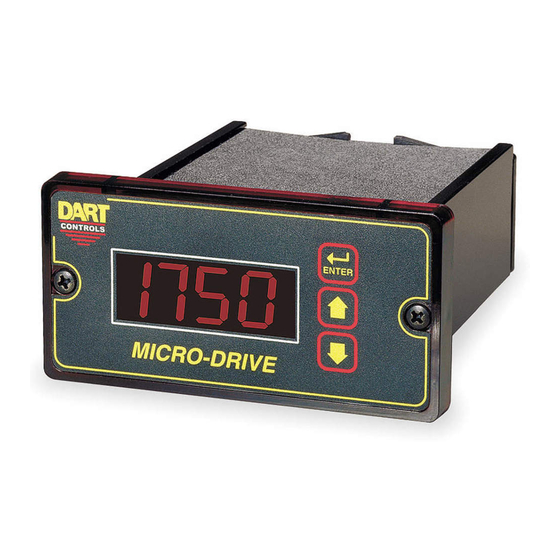
Page 14: Visual Reference
Visual Reference ENTER (Select) Button CONTROLS Page Valu Tach ENTER Display Window MICRO-DRIVE Up & Down Buttons CONTROLS ENTER Display Window ENTER (Select) Button Up & Down Buttons ENTER (Select) Button ENTER MICRO-DRIVE Up & Down Buttons Display Window CONTROLS How to Change a Parameter's Value (The Short Story) 1. -
Page 15: Detailed Configuration Instructions
Parameter-Selection Mode can be entered by simply pressing and holding the Enter button down for three seconds. Once in Parameter-Selection Mode, the far left of the display will be a ‘P’. The right side of the display will indicate the currently selected parameter number for editing purposes. Pressing the Up or Down button will increase or decrease the selected parameter number on the display. -
Page 16: Software Parameters
Description (units) Default Settings Selecting this item exits to Running Mode Read-Only Parameters Model Number 10 – MD10P Unit 10, 11, or 11 – MD3P Unit 13 – MD3E Unit Software Build 1 – 9999 Hardware Version 1 – 9999 Serial Number –... - Page 17 Software Parameters, cont'd Value Range Factory User Settings Parameter Description (units) Default Signal Input #2 (S2) Setup S2 Input Configuration 1 – Disabled (Follower Mode) 2 – E-Stop When S2 High 3 – E-Stop When S2 Low 4 – Inhibit When S2 High 5 –...
-
Page 18: Parameter Descriptions
Parameter 1 – Model Number (Read Only) This is a number which represents the base model number for the product. The model codes for the MD10P ,MD3P, and MD3E are 10 ,11, and 13 respectively. Parameter 2 – Software Build (Read Only) The software build is a code which identifies the software version of the unit. - Page 19 Parameter 14 – Keypad Mode This parameter selects the operating mode of the front-panel push buttons. In some applications, increasing or decreasing the scroll rate provides the user more controllability when entering settings. Parameters 14 and 15 affect only the Up and Down buttons when the user interface is in Running Mode.
- Page 20 Parameter 19 – Power-up Value When Power-up Mode is set to 2, this parameter will designate the default display value at power-up in display units. Parameter 20 – Display Minimum This parameter defines the lower end of the display range. This is the value which limits how low the user is able to scroll the displayed value in Running Mode.
- Page 21 Parameter 30 – Signal Input 1 (S1) Display Reference This is the number to be displayed when at the user-specified motor Reference RPM. In Rate Mode, this value represents rate units such as feet, ounces, or revolutions. In Time Mode, this value represents the reference time measured in seconds or minutes.
- Page 22 Mode 6: Jog When S2 High (Not Wired To Common) When the S2 input is at an electrically high (+5V) state or allowed to float disconnected, the MDP will enter jog mode. While in jog mode, the display will immediately change to the programmed jog setpoint, parameter 36.
- Page 23 Mode 6: Jog When UIN1 High (Not Wired To Common) When the UIN1 input is at an electrically high (+5V) state or allowed to float disconnected, the MDP will enter jog mode. While in jog mode, the display will immediately change to the programmed jog setpoint, parameter 41.
- Page 24 Mode 6: Active When Target (Display) = Zero The alarm output will activate when the displayed value is equal to zero. This allows the alarm output to be used to drive a mechanical brake to decrease stopping time or to provide holding torque at zero speed.
- Page 25 Mode 5: Silencing Enabled, Reset On S2 Input High (Not Wired To Common) Similar to Mode 4. Setting the S2 input to a high (+5V) state or allowing it to float disconnected will cause the alarm to be silenced or reset depending on the current state of the alarm conditions.
-
Page 26: Application Examples
The alarm should not be able to be silenced and should automatically reset when flow rates have returned to normal. The display should indicate in the format "xxx.x" (LPM). Application Diagram: Dart MD10P, MD3P, or MD3E Motor Control CONTROLS Page... -
Page 27: Conveyor Oven Controller With Two Preset Process Times
Coupling to or equivalent Chain Drive Gear Motor CONTROLS Page Valu Tach ENTER 6:30 Drive Train Specs: 1380 RPM at non-reduced MICRO-DRIVE motor shaft equates to 6 minutes and 40 seconds Dart MD10P, MD3P, or MD3E of tunnel time Motor Control... -
Page 28: Synchronized Conveyor Controller With Jog Switch
Description: A synchronized conveyor system comprised of two conveyors with no mechanical linkage between them. The master conveyor is driven by a basic Dart analog DC motor control. The slave or follower conveyor should follow the master's position with exacting long-term accuracy. - Page 29 Application Diagram: Box A Belt CONTROLS Motor Conveyor 1 Dart PU-20E Gear Motor Dart 253G or other Motor Control Master Side or equivalent Follower Side Box B Belt Jog Switch Conveyor 2 Gear Motor Dart PU-10E or equivalent CONTROL Page...
- Page 30 Parameter Configuration: Parameter Value Notes Follower Mode Setting Decimal point position set to XXX.X on display Display minimum is 90.0% of master rate 1100 Display maximum is 110.0% of master rate Pulses per revolution of shaft encoder or pickup is 5 PPR Pulses per revolution of shaft encoder or pickup is 10 PPR UIN1 configured as jog command when low UIN1 jog setpoint is 350 RPM...
-
Page 31: Troubleshooting
When doing this, the relay click should be audible and the NC (Normally Closed) and C (Common) terminals should become internally shorted at the terminal block. Technical Support Options • Visit the Dart Controls Web Site at: www.dartcontrols.com • Email technical support at: techsupport@dartcontrols.com •... - Page 32 COD or Credit Card (Master Card or Visa). This information is required before work can begin. If you have an account with Dart your order will be processed according to the terms listed on your account.
Need help?
Do you have a question about the MD10P and is the answer not in the manual?
Questions and answers