Table of Contents
Advertisement
Quick Links
Newport Medical Instruments, Inc.
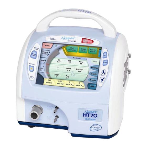
Newport HT70 Ventilator
Operating Manual
OPRHT70 Rev. A
03/10
Newport Medical Instruments, Inc.
1620 Sunflower Ave.
Costa Mesa, CA 92626
Tel: 1.714.427.5811
Tel: 1.800.451.3111 (USA Only)
Fax: 1.714.427.0489
Customer Service ext. 282
www.ventilators.com
0344
email: Info@ventilators.com
Advertisement
Table of Contents

Summary of Contents for Newport HT70
- Page 1 Newport Medical Instruments, Inc. Newport HT70 Ventilator Operating Manual OPRHT70 Rev. A 03/10 Newport Medical Instruments, Inc. 1620 Sunflower Ave. Costa Mesa, CA 92626 Tel: 1.714.427.5811 Tel: 1.800.451.3111 (USA Only) Fax: 1.714.427.0489 Customer Service ext. 282 www.ventilators.com 0344 email: Info@ventilators.com...
- Page 2 Contact Information Thank you for using the Newport HT70 Ventilator. With the HT70 you not only get a great ventilator, you get the support of Newport Medical. Since 1981 we have maintained a focused commitment to the design, production and sale of ventilators. We have dedicated our efforts to provide ventilators that are easy to use, clinically versatile, and cost effective.
- Page 3 Shipping Address: Newport Medical Instruments Attn: Receiving Department 1620 Sunflower Avenue Costa Mesa, CA 92626, USA EC REP Newport Medical Instruments, Inc. Attn: Robert Brink c/o Braun and Company Limited 11B/11C Harrier Road Humber Bridge Industrial Estate Barton on Humber...
- Page 4 FOLDOUT DRAWINGS Use the following drawings as reference while reviewing the manual sections Unfold to view drawing on reverse side OPRHT70 A0310...
- Page 5 Figure F-1 English Version- Front Panel Overview Breath Delivery Indicator. LED flashes green with every breath delivered by the ventilator. External Power LED. Lights green whenever external power is connected. This also indicates that the Integrated Battery System is being charged. Manual Inflation button.
- Page 6 Unfold to view drawing on reverse side OPRHT70 A0310...
- Page 7 Figure F-2 Symbols Version- Front Panel Overview Breath Delivery Indicator. LED flashes green with every breath delivered by the ventilator. External Power LED. Lights green whenever external power is connected. This also indicates that the Integrated Battery System is being charged. Manual Inflation button.
- Page 8 Unfold to view drawing on reverse side OPRHT70 A0310...
- Page 9 Parameter Setting buttons. Touching any one of these buttons will activate the parameter to allow adjustments. Domain button. The HT70 can be set up in one of three Domains: Basic, Transport and 14./15. Hospital. Touch to scroll through the Domain choices. Press Accept to confirm choice.
-
Page 10: Table Of Contents
Right Side Overview ..............2-2 Left Side Overview ..............2-3 Bottom Panel Labeling ............... 2-3 Set up and Pre-use Preparations Unpacking the HT70 Ventilator ........... 3-1 Assemble the ventilator .............. 3-1 Connect to A.C. power ............... 3-1 Using the Power Switch .............3-3 Make Parameter Changes ............3-3... - Page 11 Set Date and Time Screen ..........4-14 BUV Settings Screen ............ 4-14 Customize PreSets Screen ........... 4-15 Trends Screen Navigation* ............4-16 Events Screen Navigation ............4-17 Operating the HT70 Ventilator Quick Check Procedure ............. 5-1 Patient Setup Procedure ............5-5 Ventilator Alarms Setting Alarms ................6-1 Alarm Indicators .................
- Page 12 Explanations of Modes and Controls Explanation of Modes and Controls ......... 10-1 Foldout Diagrams English Version - Front Panel Overview ........F-1 Symbols Version - Front Panel Overview ........F-2 HT70 Touch Screen ..............F-3 OPR360U A0509 **Call for availability OPRHT70 A0310...
- Page 13 Section 1: ntroduction...
-
Page 14: Introduction
Section 1: ntroduction Brief Device Description ........1-1 Intended Use ............1-3 Warnings, Cautions and Notes ......1-3 OPR360U A0509... -
Page 15: Brief Device Description
Sophisticated Clinical Capabilities In addition to its durability and ease of use, the HT70 ventilator offers the complete array of clinical capabilities needed for managing critical patients. The dual micro-pistons’ ability to deliver a variable flow enables the HT70 to provide a full range of operating modes and breath types with servo-controlled, leak-compensated PEEP. - Page 16 The detachable Power Pac is ‘hot-swappable’. That is, if more battery time is needed, a depleted Power Pac can easily be removed from the back of the HT70 and be replaced with a recharged Power Pac without interrupting ventilation. No tools are needed. The Backup...
-
Page 17: Intended Use
Introduction Travel Certified The HT70 has been tested for and meets requirements for use in helicopter and fixed wing transport. Before traveling, be sure to speak with your airline representative about their particular concerns and clear all your equipment with them well before your departure. - Page 18 Do not place liquids on or near the ventilator. Damage can occur if the HT70 is exposed to extreme temperatures. Do not store the HT70 in areas where it may be exposed to temperatures below -40° C (-40° F) or above 65° C (149° F).
- Page 19 Oxygen Blending Bag. When the optional Air/Oxygen Entrainment Mixer* is secured in place, ensure that the oxygen supply is enabled prior to powering the HT70 on to avoid putting stress on the internal pump and compromising gas delivery to the patient.
- Page 20 Section 2: verview...
- Page 21 Section 2: verview of Controls, Screens and Connectors Front Panel Overview .........2-1 Touch Screens Overview ........2-1 Integrated Battery System Overview ....2-1 Rear Panel Overview ......... 2-2 Right Side Overview .......... 2-2 Left Side Overview ..........2-3 Bottom Panel Labeling ........2-3 OPR360U A0509...
-
Page 22: Overview Of Controls, Screens And Connectors
Front Panel Overview Please refer to Foldout drawing F-1 at the front of the manual. The HT70 front panel consists of easy access membrane buttons, LED indicators and the patient connection panel. The center touch screen panel provides access to alarm and parameter settings. -
Page 23: Rear Panel Overview
Overview of Controls, Screens and Connectors Rear Panel Overview 1. “Power Pac” battery pack 2. External power supply input 3. Remote alarm output Connects to Nurse Call systems. 4. Release latch Push to remove battery pack. 5. RS-232 output External communication port to communicate with central monitoring systems 6. -
Page 24: Left Side Overview
Bottom Panel Labeling The Bottom Panel of the HT70 includes a label that contains information regarding agency approvals and power ratings. Here you will find the model number and manufacturing information. - Page 25 Section 3: et-up...
- Page 26 Section 3: et up and Pre-use Preparations Unpack the HT70 Ventilator ......3-1 Assemble the Ventilator ........3-1 Connect to A.C. Power ........3-1 Using the Power Switch ........3-3 Make Parameter Changes ........ 3-3 Attach a patient circuit ........3-4 For use with a third party humidifier ....
-
Page 27: Set Up And Pre-Use Preparations
Remove all of the items from the shipping box and inspect each part and component for completeness. Verify that there is no shipping damage. For warranty protection, register your ventilator online at www.ventilators.com/warranty. The Newport HT70 Ventilator assembly includes the following parts: 1 ea. HT70 Ventilator 1 ea. -
Page 28: Connect To A.c. Power
Set up and Pre-use Preparation Connect to A.C. Power The HT70 comes with an A.C. Power Supply that includes A.C. power adapter with quick-release power plug. The detachable A.C. power cord can be ordered in country specific configurations. Only use the approved HT70 A.C. -
Page 29: Using The Power Switch
Set up and Pre-use Preparation Using the Power Switch The momentary-type power switch is located on the rear, right side of the ventilator along the bottom edge. To power the ventilator On: Press the power switch once and wait for the startup screen to appear. -
Page 30: Attach A Patient Circuit
See Figure 1: 1. Attach a bacteria filter to the Gas Output connector on the HT70. 2. Locate the short piece of 22 mm ID circuit tubing. Connect the end that includes the prox line pressure port to the inlet port of the humidifier. - Page 31 Set up and Pre-use Preparation 3. Attach the other end of the breathing circuit to the bacteria filter on the HT70. Prox line connector Breathing circuit Prox inline filter Prox line Pressure port Outlet port Humidifier Figure 2 See Figure 2: 4.
- Page 32 Set up and Pre-use Preparation See Figure 3: Exhalation valve Exhalation Valve connector Exhalation Valve tubing Breathing circuit Patient wye connector Figure 3 8. Attach one end of the exhalation valve tubing (smallest clear tubing) to the Exh. Valve connector. 9.
-
Page 33: For Use With An Hme
For use with an HME (artificial nose): See Figure 5: 1. Attach a bacteria filter to the Gas Output connector on the HT70. 2. Locate the 22 mm ID end of the breathing circuit. Attach this end to the bacteria filter. - Page 34 Set up and Pre-use Preparation Prox Line connector Gas Output connector Bacteria filter Prox inline filter Prox line tubing Pressure tee adapter (patient side) Breathing circuit Flex Tube (optional) Figure 5 7. Attach one end of the prox tubing to the Prox Inline Filter. 8.
-
Page 35: Connect Optional Accessories
Connect Optional Accessories Connect optional accessories such as the Air/Oxygen Mixer*, Low Flow Oxygen Blending Bag or Biofilter, to the right side of the HT70 at the Fresh Gas Intake Port. The D.C. Auto Lighter Cable connects into the power adapter OPR360U A0509 connector on the rear of the Power Pac battery pack. -
Page 36: Air/Oxygen Entrainment Mixer
Set up and Pre-use Preparation Air/Oxygen Entrainment Mixer* The Air/Oxygen Entrainment Mixer* (p/n MIX3212A) is used to blend atmospheric air with medical grade oxygen at a precise ratio. A control knob allows for incremental adjustment from 21 to 100 percent. The Mixer* attaches to the Fresh Gas Intake Port on the Filter Cover, located on the right side of the ventilator. -
Page 37: D.c. Auto Lighter Power Adapter
Set up and Pre-use Preparation Caution: Water in the oxygen supply can cause equipment malfunction and damage. D.C. Auto Lighter Power Adapter This cable adapter (p/n ADP3204P) allows connection to any vehicle’s D.C. power plug (12 VDC to 30 VDC). This will power the ventilator from the vehicle’s D.C. - Page 38 Section 4: avigating...
- Page 39 Section 4: avigating the Screens Start Up Screen Navigation ......4-1 Perform the Circuit Check ....... 4-2 Activate a Patient Preset ........4-3 Start Ventilation ..........4-4 Domain Navigation ..........4-4 Basic .............. 4-5 Transport ............4-5 Hospital ............4-7 Main Screen Navigation ........4-7 Alarms Screen Navigation ......
-
Page 40: Navigating The Ht70 Screens
Start Ventilation button Circuit Check button Patient Preset button When the HT70 is turned On, the ventilator will go through a short self-test and the Startup screen will appear. Confirm that the alarm sounds and the LEDS light during this short self-test. -
Page 41: Perform The Circuit Check
Navigating the Screens WARNING Ensure that all settings are appropriate for the patient prior to starting ventilation. Perform the Circuit Check Perform the Circuit Check each time the breathing circuit or exhalation valve is replaced. 1. Connect the breathing circuit to the ventilator as it will be used for your patient. -
Page 42: Activate A Patient Preset
Then touch the Circuit Check button to redo the test. If the Circuit Check fails repeatedly, try a different circuit. WARNING Do not use the HT70 if the Circuit Check fails, inadequate ventilation may result. Use an alternate method of ventilation. -
Page 43: Start Ventilation
Touch the Start Ventilation button to exit the Standby condition and begin ventilation. NOTE: Be sure to review all sections of this manual before you use the HT70 for the first time! Domain Navigation Touch the Domain button in the lower right corner of the touch screen to scroll through the domain choices, Hosp (Hospital), Trans (Transport) and Basic. -
Page 44: Basic
Navigating the Screens Basic Domain This is a simplified screen for use in a homecare or sub-acute facility type environment. The central parameter platform is enlarged for easier access. Setting changes are limited to the main parameters and the alarm settings. The Breath Type, Mode and NIV settings are displayed but cannot be set within this Domain. - Page 45 Navigating the Screens NIV settings and also to change the parameters that will display in the Monitor Data buttons. If access is needed to the Advance features and technical information, simply use the Domain button in the lower right corner of the screen to toggle to the Hospital Domain.
-
Page 46: Hospital
Hospital Domain The Hospital Domain has full access to all features and screen selections available on the HT70. This manual describes all of the features and screen selections found in the Hospital Domain. The Basic and Transport Domain features and screen selections work identically to the Hospital Domain with the limitations as noted above. - Page 47 Navigating the Screens 1. To set Alarms: Touch the Alarms button to open the alarm setting screen. Touch the desired alarm setting button to activate it (appears highlighted) then use the s t panel buttons to adjust, and then press Accept to confirm changes. See “Alarms Screen Navigation” on the following pages for more details.
- Page 48 Navigating the Screens NOTE: To increase or decrease the parameter setting rapidly, press and hold the s or t button down until the desired value appears. 8. Monitor Data buttons (four): To choose and change the parameters displayed on the Monitor Data buttons (located at the bottom of the screen) press any one of the buttons to select it.
-
Page 49: Alarms Screen Navigation
Accept. You can return to the Main screen from any of these screens by touching the screen selection button labeled “Main”. 12. Domain button: The HT70 user interface can be setup in one of three Domains: Basic, Transport and Hospital. The Basic Domain is a simplified screen for use in the homecare setting. - Page 50 Navigating the Screens To enter Alarms Screen: Touch the Alarms button to open the alarm setting screen. This same button can be used to toggle back to the Main Screen in all Domains. To set Alarms: Touch desired button to activate (highlight) an alarm limit, then use the s or t panel buttons to adjust, then press Accept to confirm changes or press Cancel to return to original settings.
-
Page 51: Advance Screen Navigation
Navigating the Screens Advance Screen Navigation (Hospital Domain) See Section 9, Specifications, for ranges and more details for each parameter. Press the Accept button to confirm changes made to any of the following parameters: 1. Slope Rise touch button, use s or t to adjust from 1 - 10 2. -
Page 52: Utility Screen
Navigating the Screens Utility Screen (Hospital Domain) Access the Utility Screen through the Advance Screen as shown above. See Section 9, Specifications, for ranges and more details for each parameter. Press Accept button to confirm changes made to any of the following parameters: 1. -
Page 53: Set Date And Time Screen
Navigating the Screens 9. Set Custom Presets touch to enter custom presets screen. See following pages 10. FiO Sensor++ touch to toggle between Enabled and Disabled 11. Software Version software version installed is displayed here 12. Hour Meter the number of hours of ventilator operation is displayed here ++Optional feature Set Date and Time Screen... -
Page 54: Customize Presets Screen
Navigating the Screens The BUV Settings Screen includes the following adjustable parameters: 1. Minimum Rate RR (respiratory rate) 2. Rate Multiplier 3. SPONT (mode) delta P (pressure target above set PEEP for breath delivery) 4. SPONT (mode) i-time 5. BUV Link (with Low MV , Apnea, or both) 6. -
Page 55: Trends Screen Navigation
Navigating the Screens 2. Make all the changes on the ventilator that you require for a selected patient group (infant, pediatric or adult). Be sure to check the settings in the Advance screen and the Alarms screen. 3. Once you are satisfied with the settings for your patient group, return to the Advance screen ¢ Utility screen and touch press the Set Custom Presets button. -
Page 56: Events Screen Navigation
Navigating the Screens To Adjust the Time Scale You can display the trends in time frames of 1, 2, 4, 8 or 24 hours. To scroll through the time scale selections simply touch the Hours button on the right side of the touch screen. Events Screen Navigation (Hospital Domain) The Events Screen displays the last 1,000 recordable events. - Page 57 Section 5: perating...
- Page 58 Section 5: perating the HT70 Ventilator Quick Check Procedure ........5-1 Introduction ........... 5-1 Equipment Needed ........... 5-1 Pretest Inspection ..........5-1 Set Up ............5-1 Standard Test Settings ........ 5-2 Quick Check Procedure ....... 5-2 Pass / Fail Check Off Sheet ......5-4 Patient Setup Procedure ........
-
Page 59: Operating The Ht70 Ventilator
Pre-test Inspection 1. Inspect the Air Intake Filter through the filter cover on the right side of HT70. Replace the filter if it is dirty. See Section 8 for replacement. 2. Examine the test lung and patient circuit to ensure that there are no holes that will cause leaks. - Page 60 1. No External Power Alarm Check Disconnect the A.C. power supply. Verify that there is an audible alarm and the alarm LEDs in the HT70 handle flash. Verify that the Ext. Power LED turns off, and the Message Area turns yellow and displays the No External Power alarm message.
- Page 61 If battery charge level is not sufficient, plug into external power to fully charge the Integrated Battery System. Remove the Power Pac battery pack. Verify that HT70 continues to ventilate, the alarm sounds, the alarm LEDs light and the message in the message area indicates that the Backup Battery is in use.
- Page 62 Operating the HT70 Ventilator HT70 Ventilator Quick Check Procedure Pass / Fail Check-Off Sheet Preparation for Use Tests Indicate result for each test 1. No External Power Alarm Check Pass _____ Fail ______ 2. Alarms & Indicators Check High #P Alarm...
-
Page 63: Patient Setup Procedure
2. Ensure the ventilator, patient circuit and accessories are assembled correctly. 3. Make sure HT70 has passed the Quick Check Procedure, and the Circuit Check. 4. Set all parameters per physician’s prescription using manual adjustment or a Patient Preset. - Page 64 Contact your health care provider or physician immediately. NOTE: To ensure best battery performance, always plug the HT70 into an external power source when it is available, even when the ventilator is not in use.
- Page 65 Section 6: larms...
- Page 66 Section 6: entilator Alarms Setting Alarms ........... 6-1 Alarm Quickset ..........6-1 Alarm Indicators ..........6-2 Alarm Silence/Reset Button ......6-2 Alarm Silence LED ........6-2 User Adjustable Alarms ........6-2 Backup Ventilation ..........6-4 Automatic Alarms ..........6-5 Battery Alarms ........... 6-7 OPR360U A0509...
-
Page 67: Ventilator Alarms
Cancel button. Alarm Quickset You can choose to have the HT70 automatically set the alarm limits. From the Alarms screen, touch Alarm Quickset and confirm by pressing the Accept button. The HT70 will monitor ventilation for 30 seconds and then set the alarm limits. -
Page 68: Alarm Indicators
1. The message area changes color according to alarm priority and an alarm message is displayed. 2. The alarm LEDs in the handle of the HT70 flash. 3. The alarm parameter button on the Alarms Screen (if it is an adjustable alarm) is highlighted. - Page 69 Ventilator Alarms while using volume controlled ventilation. To verify exhaled volumes, use a separate exhaled volume monitor. Low Pressure alarm $P The Low Pressure alarm determines the minimum pressure that must be attained in the breathing circuit during mandatory breaths. It should be set as close to the patient’s normal peak pressure as possible.
-
Page 70: Backup Ventilation
Ventilator Alarms High #FiO alarm (only available when optional O Sensor is installed and Enabled) This alarm alerts the caregiver if the oxygen percent is higher than the FiO alarm setting. Low $FiO Alarm (only available when optional O Sensor is installed and Enabled) This alarm alerts caregiver if the oxygen percent is lower than the alarm setting. -
Page 71: Automatic Alarms
Occlusion Alarm An Occlusion alarm is activated by an obstruction in the breathing circuit. The HT70 will attempt to relieve the pressure that has built up in the circuit and will not deliver additional breaths until the situation is resolved. The alarm resets when the occlusion is resolved and breath delivery will resume at that point. - Page 72 On/Off button on the back of the unit. If the cause of the System Error does not allow the HT70 to display the alarm message and the Device Alert indicator to light, the ventilator will shut down and the Shut Down Alert Alarm will activate.
-
Page 73: Battery Alarms
Pressing the Alarm Silence/Reset button will clear this alarm. Running on Backup Battery Alarm An audible alarm sounds if the HT70 has been running on the Backup OPR360U A0509 Battery for more than 15 minutes. This alarm can be silenced, but a... - Page 74 Power Pac during transport or outdoor applications. Backup Battery Failure Alarm This alarm indicates that the Backup Battery is faulty and will not safely operate the HT70. Do not use the HT70 on battery power until it has been serviced. Backup Battery Low Charge Alarm...
- Page 75 Section 7: attery Operation...
- Page 76 Section 7: attery Operation Integrated Battery System ........7-1 Power Pac Battery Pack ........7-1 Backup Battery ..........7-2 Conditions that Affect Battery Use Time ..7-2 Check the Battery Charge Level...... 7-2 Best Use Tips ............. 7-3 Battery System Maintenance ......7-3 Power Pac Battery Pack Removal ....
-
Page 77: Battery Operation
Battery System will ensure the longest life. NOTE: Always plug the HT70 into an external power source when available. Plug the HT70 into external power source even when not in use to insure best battery performance. Check battery capacity on the front panel before removing from external power. -
Page 78: Backup Battery
Power Pac battery pack every 24 months or sooner if battery operation time is insufficient for your usage. If the HT70 will be powered from the Power Pac battery pack for an extended period, ensure that the battery pack is fully charged prior to use. -
Page 79: Best Use Tips
4. Keep both the Power Pac and Backup Battery charged up. Partially discharged batteries will age faster. NOTE: Remember, the Integrated Battery System is charging anytime the HT70 is connected to external A.C. or D.C. power. Battery System Maintenance See Section 8, Cleaning and Maintenance, for more information on Integrated Battery System Maintenance. -
Page 80: Power Pac Battery Pack Removal
“PUSH” and at the same time lift up at the base of the Power Pac and slide upwards. The HT70 ventilator should always have a Power Pac battery pack installed. The A.C. power connection for the ventilator is located on the back of the Power Pac battery pack. -
Page 81: Power Accessories
American style (PWR3207P) / UK-British style (PWR3210P) / EU- European style (PWR3211P). External Battery System (BAT3300P) The Newport Medical External Battery comes in a sturdy case for OPR360U A0509 easy handling. Use the battery charger (CHG1313P) every night to recharge the external battery. Use the D.C. Auto Lighter Power Adapter (ADP3204P) to connect to the ventilator. - Page 82 Battery Operation D.C. Auto Lighter Power Adapter (ADP3204P) This cable adapter allows connection to any vehicle’s D.C. power plug (12 VDC to 30 VDC). This will power the ventilator from the vehicle’s D.C. power source and keep the Integrated Battery System charged up.
- Page 83 Section 8: leaning and Maintenance...
- Page 84 Section 8: leaning and Maintenance Cleaning and Disinfecting ........ 8-1 Ventilator ............8-1 Accessories ............8-2 Low Flow Oxygen Blending Bag ....8-2 Air/Oxygen Entrainment Mixer* ....8-2 Reusable Breathing Circuits ......8-3 Air Intake Filter ..........8-3 Proximal Inline Filter ......... 8-3 Maintenance Guidelines ........8-4 Preventive Maintenance ......8-4 Integrated Battery System Maintenance ...8-4...
-
Page 85: Cleaning And Maintenance
Caution: Do not use agents that contain acetone, toluene, halogenated hydrocarbons, or strong alkalines on the face panel or ventilator housing. Caution: Never autoclave or EtO sterilize the HT70 ventilator. These processes will damage the HT70, rendering it unusable. OPRHT70 A0310... -
Page 86: Accessories
Reusable Breathing Circuits The HT70 ventilator may be used with a standard single limb or “J” style breathing circuit with a quality exhalation valve. Reusable breathing circuits are generally provided in clean, but not sterile, condition. -
Page 87: Air Intake Filter
Filter weekly. Replace with a new filter when the majority of the filter surface area is no longer white. Intake Filters are not reusable. WARNING NEVER operate the HT70 without a clean Air Intake Filter in place. NEVER reverse the Air Intake Filter when dirty. -
Page 88: Maintenance Guidelines
Cleaning and Maintenance Newport Medical strongly recommends that extra Prox Inline Filters be available at all times when using the HT70 ventilator WARNING Always use a Proximal Inline Filter (p/n HT6004701 or equivalent) at the Prox. Line Connector to protect the internal pressure transducers from moisture or other contaminants. -
Page 89: 10,000 Hour Maintenance
1. Whenever possible, plug into external power source to charge the batteries. 2. Use the optional D.C. Auto Lighter Cable accessory to power the HT70 when traveling by automobile or to connect to an external battery. See Section 7, Battery Operation for more information on the proper operation of the HT70 Integrated Battery System. -
Page 90: Warranty
Warranty The Newport HT70 Ventilator is guaranteed to be free of defects for a period of two (2) years from invoice date of purchase. The following are exceptions to this warranty: 1. -
Page 91: Factory Maintenance Or Repair
(10) days of equipment receipt. The above is the sole warranty provided by Newport Medical. No other warranty, expressed or implied, is intended. Representatives of Newport Medical are not authorized to modify the terms of this warranty. -
Page 92: Repacking/Return Information
Prior to returning your ventilator for service or repair you must obtain a returned goods authorization number (RGA) from our Technical Service Department. Refer to the HT70 Service Manual or contact Technical Service department for complete instructions. See Contact Information page at the front of this manual for address, phone and website details. -
Page 93: Specifications
Section 9: pecifications... - Page 94 Section 9: pecifications Front Panel Buttons - Symbols Version ..9-1 Miscellaneous Reference Symbols ....9-2 Controls / Monitors ........... 9-2 Monitor Data Selections ........9-3 Front Panel Membrane Buttons and Indicators ............ 9-3 Alarms ..............9-4 User Adjustable Alarms ....... 9-5 Automatic Alarms .........
-
Page 95: Front Panel Buttons - Symbols Version
Specifications Front Panel Buttons - Symbols Version Accept Cancel Alarm Silence Reset / LED Breath Delivery Indicator Brightness Device Alert LED External Power LED Manual Inflation Up/Down Arrow OPR360U A0509 OPRHT70 A0310... -
Page 96: Miscellaneous Reference Symbols
Specifications Miscellaneous Reference Symbols Manufacturer Name and Address EC REP Authorized Representative in the European community Main Power Off / On (momentary switch) Low (Paw or Min Vol) alarm High (Paw, Min Vol or RR) alarm Attention, see instructions for use Equipotentiality Applied Parts Type BF Brightness control... -
Page 97: Monitor Data Selections
Specifications Controls / Monitors Range / Selection Resolution I:E Ratio 1:599 to 3:1 0.1 for 9.9:1 to 1:99 and 1 for 99:1 to 1:99 Airway Pressure –10 to 100 cmH O / –10 to 98 mbar Gauge includes indicator bars to show low and high PAW alarm limits Optional O Sensor... -
Page 98: Alarms
Specifications Front Panel Membrane Buttons and Indicators Up / Down Arrows Arrow buttons allow adjustment of settable s / t parameters. Use up arrow to increase and down arrow to decrease. Brightness control Press to select brightness levels, maximum, medium high, medium and low. Manual Inflation 3 second maximum. -
Page 99: User Adjustable
Specifications User Adjustable alarms Alarm Range / Description Priority P (High Pressure) High 4 to 99 cmH O / 4 to 99 mbar P (Low Pressure) High 3 to 98 cmH O / 3 to 98 mbar, limited by ≥ PEEP + 3 (when NIV is active – 1-98 cmH O /mbar Min Vol (High Insp. -
Page 100: Hardware Requirements
Specifications Automatic alarms Alarm Description Priority Shut Down Alert High On to Off Shut Down Alert, silence by pressing Alarm Silence/Reset button Motor Fault High Hardware detected fault in the motor drive circuit has occurred Internal Temperature Internal temperature is > 60° C Backup Battery Backup Battery temperature is >... -
Page 101: Environment
O /mbar, Power Save mode On, Bias flow Off. NOTE: The Power Pac and Backup batteries are charged whenever the HT70 is connected to an external power source. Battery charge level is best maintained by keeping the HT70 continuously connected to external power. -
Page 102: Size And Weight
Operating Humidity 15 to 95% non-condensing Operating Altitude Sea level to 15,000 ft (0 to 4,572 m) There is no altitude limitation when HT70 is operated in a pressurized environment. Operating Pressure 600 to 1,100 mbar Storage and Shipping Temperature –40ºC to 65ºC... -
Page 103: (Optional) Air / Oxygen Entrainment Mixer
Specifications (Optional) Air / Oxygen Entrainment Mixer (MIX3212)* Specifications Pneumatic Requirements: Oxygen 35 to 90 psig (2.4 to 6.2 Bar) full operating range 40 to 50 psig (2.7 to 3.4 Bar) accuracy ± .08 Atmospheric pressure FiO2 Control adjusted continuously from 0.21 to 1.00 NOTE: Oxygen source gas must be medical grade, 100% oxygen. -
Page 104: Regulatory And Agency Standards
Specifications Regulatory and Agency Standards Testing and evaluation of the HT70 Ventilator has been conducted in compliance with the following voluntary standards: ASTM F 1100-90:1997 Standard Specifications for Ventilators Intended for Critical Care Use ASTM F 1246-91:2005 Standard Specifications for Electrically Powered Home Care Ventilators –... - Page 105 Section 10: xplanation of Modes and Controls...
- Page 106 Section 10: xplanation of Modes and Controls A/CMV ...............10-1 SIMV Mode ............10-1 SPONT Mode ............10-1 NIV (Non Invasive Ventilation) ......10-2 PS (Pressure Support)* ........10-2 PC (Pressure Control) ........10-2 VC (Volume Control) ........10-3 Backup Ventilation .......... 10-3 * Not available on all models OPR360U A0509...
-
Page 107: Explanations Of Modes And Controls
When PEEP/CPAP is set above 0, the ventilator mode is CPAP (without PS) or Bi-level Positive Airway Pressure (with PS). Ensure that Ptrig is set so the HT70 detects all spontaneous patient efforts. * Not available on all models 10-1... -
Page 108: Niv (Non Invasive Ventilation)
As with all HT70 operating modes, Backup Ventilation is activated if the BUV linked alarm is violated. (Non Invasive Ventilation) The HT70 can be used for noninvasive ventilation in all modes. Press the NIV button on the left side of the touch screen to toggle On noninvasive. -
Page 109: Vc (Volume Control)
Explanation of Modes and Controls occurs when (1) the set i time elapses, or (2) Paw exceeds the Pressure Control setting by 8 cmH O (mbar). Maximum airway pressure won’t exceed the user set High P alarm setting. The target airway pressure for pressure controlled mandatory breaths in A/CMV and SIMV is the display setting above ambient pressure, not above PEEP. - Page 110 Explanation of Modes and Controls Backup Ventilation is not active for 60 seconds after the user adjusts ventilator controls, changes modes or starts ventilation from the Setting condition. During Backup Ventilation, the Alarm Silence/Reset button can be pressed to silence the audible alarm. This will not cancel Backup Ventilation.
- Page 111 Ventilation is canceled. If linked to Apnea Alarm, after 2 minutes of Backup Ventilation it is canceled. At that time the audible alarm stops, the alarm indicator latches and the HT70 resumes ventilation at the user-selected parameters. Press the Alarm Silence/Reset button to cancel the latched alarm indicator and alarm message in the Message Display Window.
Need help?
Do you have a question about the HT70 and is the answer not in the manual?
Questions and answers