Table of Contents
Advertisement
Quick Links
Advertisement
Table of Contents

Summary of Contents for EBONITE MILL DRILL
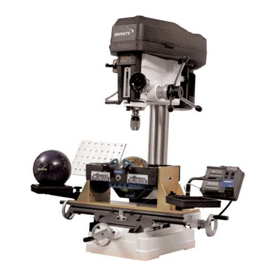
- Page 1 EBONITE MILL DRILL OPERATIONS MANUAL REV A 12-2-05...
-
Page 2: Table Of Contents
EBONITE MILL DRILL OPERATIONS MANUAL Table of Contents Mill Drill Set-Up Section (1) Receiving New Machine____________________________________3 Section (2) Locating New Machine_____________________________________3 Section (3) Preliminary Set-Up________________________________________4 Section (4) Optional Accessories_______________________________________7 Section (5) Electrical________________________________________________7 Section (6) Final Calibration__________________________________________7 Mill Drill Operations Section (1) Pivoting Jig_____________________________________________10... -
Page 3: Ebonite Mill Drill Operations Manual
The Mill Drill Crate is 4’ x 4’ x 6 ½’ and generally will not fit through the entry doors of the bowling center. Therefore remove the 4 sides and the top to the crate by removing all the Phillips head screws and discard them, before attempting to move the machine in the bowling center. -
Page 4: Section (3) Preliminary Set-Up
Extreme care should be used as this machine is top heavy so use of the wooden base ( caution and care 3. Roll the machine in the center to the front of your shop, measure the width of your door to make sure you can get the machine thru. If the door you must use is narrow simply set the machine down and then slide the dolly under the stand from the side of Again use caution and, make sure you have plenty of help as the machine the machine (... - Page 5 2. On the left hand side of the machine there is a black crank handle, cranking this will begin to raise the head of the machine until it is high enough to turn the head to its proper position. Turn the head. Pictured Below. 3.
- Page 6 4. There will also be another scribed line on that runs up and down on the post along with another one scribed into the bottom of the head, pivot the head of the machine until these two lines are matched up. Once this is done tighten the large nuts on the right hand side again.
-
Page 7: Section (4) Optional Accessories
Section (4) Optional Accessories of your new machine 1. Place the drill bit holder on the machine and unpack the drill bits and place in the holder 2. Place the Ball holder accessory arm on the left hand side of the machine and the tool holder on the right hand side. - Page 8 use the table handle on the front of the machine and adjust the table forward and back until the blade fits perfectly on the ball. As a double check take a dollar bill and slide under the front edge of the blade and then the back. If you have adjusted the table properly you will be able to slide the bill under the blade the same amount from each end.
- Page 9 7. Next before moving the tables, look on the inside of the front and the right handles, each one has a ring with marks that indicate .001 of and inch. Each of these rings has a thumb screw, loosen the thumb screw and turn the ring so the 0 on the ring lines up on the line, then tighten the thumb screw.
-
Page 10: Mill Drill Operations Section (1) Pivoting Jig
Mill Drill Operations Section (1) Pivoting Jig Option How to use the Power House Pivoting Jig The Pivoting jig is a 4 axis jig that is designed to allow the operator to drill all 3 holes with out removing the ball from the jig. Using the proper sequence you can also install a thumb slug, oval the slug and trim the slug before removing the ball. - Page 11 away from you. If you want left lateral the ball will move to the right, if you want right lateral the ball will move left. As an indicator for right and left if you look at the ruled scale on the front of the machine left will be left of zero and right will be right of zero. 6.
-
Page 12: Section (2) Installing Slugs
it is not you can change it at this point by making an arc from each finger using the proper span for each finger. By following this process you have check points that allow you to prevent a costly mistake. 14. - Page 13 5. Place a small amount of glue in the hole about an inch below the surface then take the slug your are wanting to use and place at the top of the hole, set another slug on top of it and then pull the chuck down to the slugs. Next continue pulling the chuck down until the slug seats in the bottom of the hole.
-
Page 14: Section (3) Trimming Ball Plug
If you have never drilled these before we suggest some practice before working with a customer. The following is the process when using the Mill Drill machine. There are a few things to remember when using ovals. Section (4a) Measuring for Oval Holes 1. -
Page 15: Section (4B) Proper Angle
6. When drilling the first oval for a customer we recommend that they are there for the entire process as you can be more accurate, after the first one the Mill Drill machine will allow you to recreate or duplicate each step as long as you noted each move on your spec sheet. -
Page 16: Section (5) Drilling Ovals
1. Using the calipers that were supplied with your Mill Drill machine measure the thickness of the thumb. Simply slide the calipers up and down over the knuckle. Once you have the setting that will gently slide up and down on the thumb mark that on your drill sheet as the thumb hole size. - Page 17 5. Make your table movement for Y again double checking yourself by pulling the bit close to the ball making sure you’re going to cut where you want. 6. When you’re sure you have moved the right direction turn the machine on and slowly pull the bit into the hole.
-
Page 18: Oval Drilling Guide Chart
OVAL DRILLING GUIDE For drilling an oval at angle alpha back a distance Z you must move the table a distance X over and Y up. OVAL OVAL WIDTH (Z) (THOUSANDS, 0.001”) ANGLE (ALPHA DEGREES) 28 10 56 21 85 31 13.5 27 13 40.5 19.5 54 25 67.5 31.5 82 38 95.5 44.5 109 26 15... -
Page 19: Section (1A) Programming
Digital Reader Program Instructions Section (1a) Programming Several functions of the digital display are user programmable. The following instructions describe what features are available and how to change the system’s defaults to customize the display for a particular application. The Keys pictured have multiple functions. Timing, which is how long a key, is depressed, and momentarily the combination of the keys pressed is important. - Page 20 CAUTION: The Limit Mode (See Programming 14, 15, 16, 17) functionality is still active even while the display is in programming mode. Changing LIMITS may result in the Limit/Monitor Signal hardware output becoming active immediately. press and hold momentarily To exit programming mode, the MODE key and then press the 0 (zero) key.
- Page 21 Pr5 – Metric Display Units [0, 1] Controls whether the measured value is displayed in millimeters or Centimeters when in metric mode. 0 = millimeters 1 = centimeters Pr6 – Disable Fractions/Inches [0, 1, 2] 0 = All measurements modes (millimeters or centimeters, inches and fractions) 1 = No Fractions.
- Page 22 Pr11 – Offset Addition 1 [-999.999 to 999.999in] or [-9999.99 to 9999.99mm] When offset 1 is selected (see section 4 – Offset Addition), this value is added to the current ABS position. Default: 2.000IN Only active if Pr10 is set to 1. Note: Default is set in inches Pr12 –...
- Page 23 Pr18 – Drift Tolerance [.01 to 9999.99mm] or [.001 to 999.999in]. Range of motion allowed (+ or -) while in Monitor mode. Default = .01IN. Note: Default is set in Inches Pr19 – Automatic Monitor ON Time [0, 1 or 2] Configures display to automatically activate Monitor mode after 30 or 60 seconds of encoder inactivity.
-
Page 24: Section (1B) Lcd
Section (1b) LCD The above figure illustrates all the segments available on the Digital Display. Section (1c) Display Keys MODE ON/OFF Section (1d) ON/OFF Momentarily pressing the ON/OFF key will cause the display to turn on or off. The Firmware Version is displayed on power-up or when ON/OFF key is pressed. -
Page 25: Section (1F) Lock Mode
The digital display can show measurement information in imperial or metric. To change the current display mode, momentarily press the MODE key. With each key press the display will cycle through decimal inches, fractional inches (1/16), (1/32), (1/64) (If enabled by Programming Parameter Pr6) and metric (mm or cm based on setting of Programming Parameter Pr5). -
Page 26: Section (1H) Offset Addition
capability in which the read head can calculate its position on any individual scale segment but cannot determine which particular segment it is on. To solve this problem, the Digital Display track which scale segment the read head is on by detecting the “splice” between one segment and adjacent segments. -
Page 27: Section (1J) Scaling
programming parameters Pr16 and Pr17 but are only active if Pr14 is set to 1. Display toggles between current position display and “LL” or “UL”. The position is shown for 2 seconds and the “LL” or “UL” is shown for 2 seconds. This continues as long as a limit has been exceeded. Limit monitoring is always active, even in programming mode. -
Page 28: Supplement
Installing Pivoting Jig on existing Mill Drill: The Mill Drill jig was designed not only to be used as a new complete unit but also it can be used as an upgrade to most any existing milling machine. Because of its low profile it can be added to most any milling machine with very few modifications. -
Page 29: Service Contact Information
For Customer Service and Technical Support Contact: Gerry Keslar Ebonite Vantech 1808 Dawson Springs Road Hopkinsville KY 1-270-885-3373 REV A 12-2-05...
Need help?
Do you have a question about the MILL DRILL and is the answer not in the manual?
Questions and answers