
Related Manuals for DataApex Shodex RI-101

Summary of Contents for DataApex Shodex RI-101
- Page 1 Clarity Controls Shodex RI-101 Code/Rev.: M159/70A Date: 27.8.2016 Phone: +420 251 013 400 DataApex Ltd. Fax: +420 251 013 401 Petrzilkova 2583/13 clarity@dataapex.com 158 00 Prague 5 www.dataapex.com The Czech Republic...
- Page 2 Clarity ® , DataApex ® and ® are trademarks of DataApex Ltd. Microsoft ® and Windows TM are trademarks of Microsoft Corporation. DataApex reserves the right to make changes to manuals without prior notice. Updated manuals can be downloaded from www.dataapex.com. Author: DM...
-
Page 3: Table Of Contents
Shodex RI-101 Table of Contents Contents 1 Shodex RI-101 Control Module 2 Requirements 3 Installation Procedure 3.1 Shodex RI-101 detector communication 3.2 Clarity Configuration 4 Using the control module 4.1 Method Setup - Acquisition 4.2 Method Setup - Advanced 4.3 Hardware Configuration 4.4 Device Monitor... - Page 4 Table of Contents Clarity Controls To facilitate the orientation in the Shodex RI- 101 manual and Clarity chromatography station, different fonts are used throughout the manual. Meanings of these fonts are: Instrument (blue text) marks the name of the window to which the text refers. Open File (italics) describes the commands and names of fields in Clarity, parameters that can be entered into them or a window or dialog name (when you already are in the topic describing the window).
-
Page 5: Shodex Ri-101 Control Module
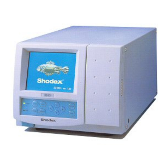
Shodex RI-101 1 Shodex RI-101 Control Module 1 Shodex RI-101 Control Module This manual describes the setting of the Shodex RI-101 , RI-102 and RI- 104 detector. The control module enables direct control of the instrument over serial line. Fig 1: Shodex RI-101 detector Direct control means that the detector can be completely controlled from the Clarity environment. -
Page 6: Requirements
Shodex RI-101 2 Requirements 2 Requirements Clarity Installation DVD-ROM with LC Control (p/n A24) or GC Control module (p/n A23) license. Free serial COM port in the PC. Note: Modern computers usually have only one (if any) serial (COM) port installed. -
Page 7: Installation Procedure
3 Installation Procedure 3 Installation Procedure 3.1 Shodex RI-101 detector communication The Shodex RI-101 is controlled by serial (RS232) communication. It uses a standard serial DB9F-DB9M straight cable (p/n SK02) described in the picture below. Fig 2: Serial DB9F-DB9M straight cable... -
Page 8: Clarity Configuration
3 Installation Procedure Clarity Controls 3.2 Clarity Configuration Fig 3: How to Add Shodex RI-101 module Start the Clarity station by clicking on the icon on the desktop. Invoke the System Configuration dialog accessible from the Clarity window using the System - Configuration... command. - Page 9 You may fill in the custom Device Name. Note: DataApex UNI Setup dialog is described in detail in the chapter "DataApex UNI Setup" on pg 12. ④ The Shodex RI-101 item will appear in the Setup Control Modules list of the System Configuration dialog.
-
Page 10: Using The Control Module
Shodex RI-101 4 Using the control module 4 Using the control module After adding and setting up the detector a new Acquisition tab will appear in the Method Setup dialog. A new Shodex RI- 101 detector section enabling the monitoring of the current detector state will be also created in Device Monitor window. -
Page 11: Method Setup - Acquisition
Method Setup - Acquisition tab serves for setting the common parameters of the Shodex RI-101 detector. If more than one detector is available, it is possible to select between them by using the Select Detector combobox on the top of the dialog. - Page 12 Setting this parameter to other value than Sampling Period means that the detector will filter the data and only send averaged values to Clarity. Temperature [°C] Defines the working temperature of the Shodex RI-101 detector. Equilibration Temperature Tolerance [°C] Serves for the setting of the target temperature tolerance. When the temperature reaches the desired value with the tolerance set here, the detector gets to the READY state.
-
Page 13: Method Setup - Advanced
4.2 Method Setup - Advanced Method Setup - Advanced tab serves for setting the usage of auxiliary signals of the Shodex RI-101 detector. Fig 6: Method Setup - Advanced The list of available auxiliary signals is shown in the table in the lower part of the dialog. -
Page 14: Hardware Configuration
4.3 Hardware Configuration Hardware Configuration dialog (invoked by using the Det Status button from the Method Setup - Acquisition dialog) displays the configuration of the Shodex RI-101, namely the communication type and its parameters. Fig 7: Hardware Configuration - 10 -... -
Page 15: Device Monitor
4 Using the control module Clarity Controls 4.4 Device Monitor The window with the detector status can be invoked by the Monitor - Device Monitor command from the Instrument window or using the Device Monitor icon. Fig 8: Device Monitor - Detector Autozero Zeroes the connected detector. -
Page 16: Dataapex Uni Setup
Fig 9: DataApex UNI Setup Ruby Script Displays the selected Ruby Script. The correct SHODEXRI101DET.RB script for the Shodex RI-101 detector can be found in the UTILS/UNI_ DRIVERS/SHODEX subdirectory (accessible through the button) of the Clarity installation folder (C:\CLARITY\BIN by default). -
Page 17: Report Setup
Shodex RI-101 5 Report Setup 5 Report Setup The detector section on the method report can be enabled by checking the Instrument Control checkbox on the Method tab of the Report Setup dialog. Auxiliary signals setting made on Method Setup - Advanced will be also printed. -
Page 18: Troubleshooting
Note: Instead of COM1, type the communication port used to communicate with the Shodex RI-101 detector. This port number is displayed when the Det Status button in the Method Setup - Acquisition dialog is invoked. Note: %D (or %d) in the filename parameter means that the log will be created separately for each day.
Need help?
Do you have a question about the Shodex RI-101 and is the answer not in the manual?
Questions and answers