
Summary of Contents for Digitus DS-72001
- Page 1 ® DIGITUS TFT Console User Manual DS-72001 • DS-72002 • DS-72003 DS-72011 • DS-72012 • DS-72013...
-
Page 2: Table Of Contents
INTRODUCTION ........................... 3 FEATURES ........................... 4 PRODUCT TYPE .......................... 5 VIEW OF PRODUCT ........................6 Front View ..........................6 Dimension ..........................8 KVM SWITCHES PACKING LIST ....................9 KVM Control Platform Connecting Wire ................10 KVM Control Platform Power Wire ..................10 OPERATION .......................... -
Page 3: Introduction
INTRODUCTION A KVM control platform integrates a multiple-port KVM switch into a 1U height. It controls multiple PCs from only one platform (keyboard, mouse and monitor). A KVM switch can control 8/16 PCs by direct connection and 256 PCs by 2 level cascade connection. -
Page 4: Features
FEATURES Control Platform Control platform with LCD, keyboard, mouse and multiple ports KVM switch 1U height, suitable for 19’’ standard cabinet installation and metal structure 17/19’’ LCD screen with high brightness, high clear and high resolution Control platform can be totally pulled out from the cabinet and the LCD screen can be turned on to 120 degrees ... -
Page 5: Product Type
PRODUCT TYPE Type Function Note DS-72001GE/US 17 inches LCD screen, keyboard and mouse DS-72002GE/US 17 inches LCD screen, keyboard, mouse and 8/16 DS-72003GE/US ports USB KVM DS-72011GE/US 19 inches LCD screen, keyboard and mouse DS-72012GE/US 19 inches LCD screen, keyboard, mouse and 8/16 DS-72013GE/US ports USB KVM... -
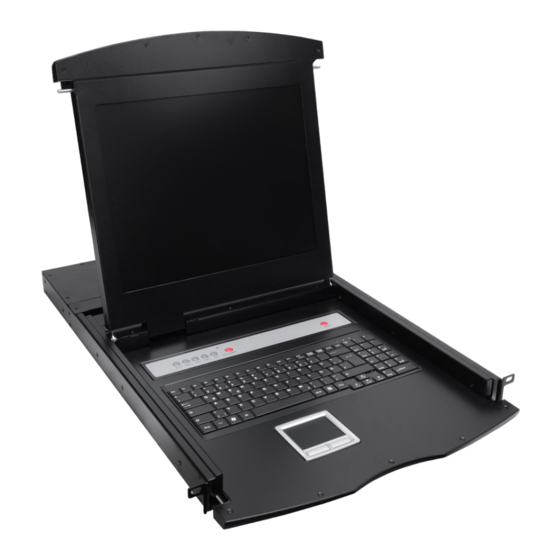
Page 6: View Of Product
VIEW OF PRODUCT FRONT VIEW 1. Front Panel 2. Handle 3. LCD screen 4. Keyboard 5. Mouse touch board 6. Rear hang ear channel 7. Guide 8. Front hang ear 9. LCD OSD control key... -
Page 7: Rear View
REAR VIEW DS-72001GE/US – DS-72011GE/US DC 12V DS-72002GE/US – DS-72012GE/US DC 12V 1 2 3 4 DS-72003GE/US – DS-72013GE/US... -
Page 8: Dimension
1. IP Module Restore to Default Plug needle or ballpoint pen into the hole to restore the IP module to default setting. 2. RJ45 Port CAT UTP can be plugged into it to be connected to the LAN including the controlling computer. -
Page 9: Kvm Switches Packing List
19’’ / 19”wide screen: PACKING LIST Type Name Num/Unit Note 17 inches LCD screen, DS-72001GE/US KVM Control Platform keyboard and mouse control DS-72002GE/US platform integrated KVM switch DS-72003GE/US with multiple ports (8/16ports). 19 inches LCD screen, DS-72011GE/US KVM Control Platform keyboard and mouse control DS-72012GE/US platform integrated KVM switch... -
Page 10: Kvm Control Platform Connecting Wire
KVM CONTROL PLATFORM CONNECTING WIRE Cable Type KVM Port PC, or Server Port VGA port VGA, Keyboard, Mouse USB and PS/2 (Keyboard, mouse and (Standard USB & Connecting Cable monitor) PS/2 Interface) USB and PS/2 Connecting Cable KVM CONTROL PLATFORM POWER WIRE Wire Type Note Voltage Range... -
Page 11: Operation
OPERATION CONNECTION OF KVM SIGNAL WIRE Connect the end with 8 sockets to the KVM control platform, and the other one to the computer. DC 12V Power supply Before Use Make sure all the devices are safely grounded ... -
Page 12: After Use
Then open the front panel and the LCD can be turn on to 120 degrees. As shown below: AUTO LOCK UNLOCK Press LCD power key (red), the LCD is on After Use Press LCD power key -> the LCD power turns off ... -
Page 13: Assembling & Disassembling
Assembling & Disassembling The device can be assembled and disassembled as follows:... - Page 14 STANDARD RACK INSTALLATION 1. Screw the front flange to the rack first. Slide the bars with the rear flange towards the rack until the flanges gets contact with the rack, then screw the rear flanges to the rack. 2. Slide the switch onto the support flanges. Use the screws supplied with this package to loosely attach the front of the switch to the front of the rack.
-
Page 15: Single Stage Installation
4. Use the screws supplied with this package to attach the bars to the rear of the switch. SINGLE STAGE INSTALLATION To set up your installation, do the following: 1. Plug your USB / PS/2 keyboard, USB / PS/2 mouse and monitor into the console port section located on the unit’s rear panel 2. -
Page 16: Cascade Installation
CASCADE INSTALLATION To set up cascade installation, do the following: 1. Set up single installation as mentioned in SINGLE STAGE INSTALLATION. 2. Connect one end of HDB15 cable to IN port of upper KVM, and the other end to OUT port of lower KVM. - Page 17 Level LCD KVM or KVM 2nd Level KVMs DESCRIPTION FOR CASCADE: 1. Before cascade KVMs. Need to change the OSD hotkey. The 1st level KVM and the 2nd level of KVM hotkey must be different; The default hotkey setting for hotkey is: [Ctrl][Ctrl] 2.
-
Page 18: Osd Operation
OSD OPERATION OSD OVERVIEW The On Screen Display (OSD) is used to handle all computer control and switching procedures. All procedures start from the OSD main menu. To pop up the main menu, tap the [Ctrl] twice. Note: You can optionally change the hotkey to the [Scroll Lock] or [Shift] or [Alt] in OSD F6 SET function. -
Page 19: Osd Main Screen Headings
OSD MAIN SCREEN HEADINGS Heading Explanation This column lists the port numbers for all the CPU ports on the installation. The simplest method to access a particular computer is to move the highlight bar to it, then press [Enter]. If a port has been selected for Quick View scanning, an arrowhead symbol displays in this column to indicate so. - Page 20 Choice Meaning Lists all of the ports on the installation. QVIEW Lists only the ports that have been selected as Quick View Ports. POWERED ON Lists only the ports that have their attached computers powered on. POWERED ON + Lists only the ports that have their attached computers powered on QVIEW and have been selected as Quick View Ports.
- Page 21 CHANNEL DISPLAY DURATION Time the tip window last. Options are following: 3 SECOND the tip window lasts for 3seconds. ALWAYS ON The tip window always on the screen. Move the highlight bar to an option and press [Enter] to select it. CHANNEL DISPLAY POSITION Position of the tip window: A small blue window appears on the screen.
-
Page 22: Safety Guide
SAFETY GUIDE Please follow the directions below when installing, using and maintaining it in order to guarantee the device to work well. When installing and operating the device, please make sure proper power supply first, and then do other operations after it is initialized. ...
Need help?
Do you have a question about the DS-72001 and is the answer not in the manual?
Questions and answers