Table of Contents
Advertisement
Advertisement
Table of Contents

Related Manuals for Saitek X52

Summary of Contents for Saitek X52
- Page 1 WINDBOX JOYSTICK RADIO CONTROL SYSTEM INSTRUCTION MANUAL...
-
Page 2: Table Of Contents
2.OverallLayoutofGroundStation ........5 2.1Exterior&Interface ......... 5 2.2BasicOperation ..........6 2.3InsertNewJoystick .......... 7 2.4ThrottleAlarm ..........8 2.5DefaultsettingofJoystickX52orX52pro ..... 9 3.InstructionofMenuOperation ........10 3.1WINDBOXButtonsforMenuOperation ..... 10 3.2SystemHomeScreen ........11 3.3Sub-menuOperations ........11 ... - Page 3 4.9Output16ChannelsofPWMSignalswithUsingTwoReceivers21 4.10FailSafeSetting ........... 22 4.11ButtonMonitor ........... 23 4.12ButtonMapping .......... 24 4.13CancelButtonMapping ........27 4.14ShortcutSettingforUnlockingActionofmulti-rotorcraft ..28 4.15SetSix-segmentSwitchofAPM/PIXFlyController ..30 4.16MappingLinearaxisoftheJoysticktotheChannel ..31 4.17CanceltheMappingoftheaxisofJoystick ....32 4.18TrainerSetting ..........33 4.19Connectwith433/915MRangeExtender ....35 ...
-
Page 4: Introduction
1. Introduction ThankyouforpurchasingaWINDBOXseriesdigitalproportionalR/C system.Thissystemisextremelyversatileandmaybeusedbybeginners andprosalike.Inorderforyoutomakethebestuseofyoursystemand toflysafely,pleasereadthismanualcarefully.Duetounforeseen changesinproductionprocedures,theinformationcontainedinthis manualissubjecttochangewithoutnotice. ThisRCControlsystembridgesthegapfromconventionalreal aircraftandRCaircraftallowingforRCpilotstoexperiencearealistic experienceandrealaircraftpilotsafamiliarcontrolinterfacewhen transitioningtohobbymodels.TheGroundcontrolsystemisalso perfectforroboticsandotherRChobbyuses.... -
Page 5: OverallLayoutOfGroundStation
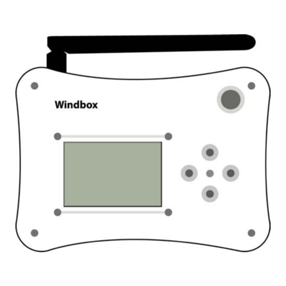
2. Overall Layout of Ground Station 2.1 Exterior & Interface ... -
Page 6: BasicOperation
2.2 Basic Operation 1. Screwtheantennaintotheantennainterfacefromthetop,and inserttheUSBflightjoystickintotheUSBinterfaceatthebottomof theequipment,andconnecttheextensioncordfromthepower interfacewiththebatterywhichcanbe2S(8.4V)or3S(12.6V). 2. PressthepowerswitchtoelectrifytheequipmentandtheLCD screenisthereforeturnedon.Atthistime,theequipmentwillstart toworknormally.Presstherightbuttononthemainpaneltoenter intomenusettingsandpresstheup-downbuttonstoselectthe menu.... -
Page 7: InsertNewJoystick
3. Linkthereceivertothecontrolledequipment,andthenthe controlledequipmentcanberemotelycontrolledthroughtheUSB flightjoystick. 2.3 Insert New Joystick WhenthesystemdetectednewUSBjoystick,itwillaskwhetherto activatethenewjoystick.Iftheanswerisyes,thesystemwillclear currentconfigurationandacceptthenewlyinsertedjoystickas primarydevice. ... -
Page 8: ThrottleAlarm
2.4 Throttle Alarm Duringtheinitiationofthesystem,ifthethrottleisnotatthelowest position,thesystemwillalarm,andsuspenduntiltheuseradjustthe throttletothelowestposition.Iftheuserclicked“CloseRF”,theRF systemwillbeshutdowntoprotecttheuserwhenthesystemis initiated. ... -
Page 9: DefaultSettingOfJoystickX52OrX52Pro
2.5 Default setting of Joystick X52 or X52pro 1. CH6/Twistswitch 2. CH5/Twistswitch 3. Throttle 4. Aileron 5. Rudder 6. Elevator 7. CH8/3Gradesswitch 8. Roll/Pitchmintrimswitch 9. Multi-rotorunlockkey 10. Yawmintrimswitch 11. CH7/3Gradesswitch... -
Page 10: InstructionOfMenuOperation
12. Systemmenukey 3. Instruction of Menu Operation 3.1 WINDBOX Buttons for Menu Operation Press“MenuRightButton”toentermainmenuwhenunderthe systemhomescreen.... -
Page 11: SystemHomeScreen
3.2 System Home Screen A.Atimerisontheleftoftheinformationbar B.InsertedUSBjoystickstatusisinthemiddleoftheinformationbar C.Thebatteryvoltageisontherightoftheinformationbar D.4-channelsdataisinthemiddleofthescreen 3.3 Sub-menu Operations ... - Page 12 Forenteringsub-menu,press“MenuRightButton”whenundermain menu. Sub-menuOperation A.Back:press“MenuLeftButton”toreturntoupperlevelmenu.Press “MenuUp”and“MenuDown”buttonstoselectsub-menu. B.Menuwithoutoptions:press“MenuLeftButton”toreturntoupper levelmenu.Press“MenuRightButton”toentersub-menu. C.Menuwithoptions:press“MenuLeft”and“MenuRight”button tosettheparameters. D.Theuparrowattheuprightcornerofthemenuscreenindicates previouspageavailable. E.Thedownarrowatthedownrightcornerofthemenuscreenindicates nextpageavailable. ...
-
Page 13: Functions
4. Functions 4.1 Servo Monitor Thisfunctioncanbeusedtomonitorthevaluesofallchannels.Thefirst pageshowsthevaluesofthefirsteightchannels;press“MenuDown Button”tomovetonextpageforthevaluesofothereightchannels. Press“MenuLeftButton”toreturntoupperlevelmenu. ... -
Page 14: TrimSetting
4.2 Trim Setting ●Optionone:selecttargetedchannel ●Optiontwo:thevalueoftrim ●Optionthree:Resettrim.sub-trimisresettotheinitialvalue. 4.3 D/R Setting Thisfunctioncanbeusedtoadjusttheoutputrangeofthechannel. ●Optionone:disableorenableallchannelsdualratefunctions. ●Optiontwo:choosetargetedchannel.... -
Page 15: ChReverseSetting
●Optionthree:changetheratevalueofthetargetedchannel.The defaultvalueis100%;adjustablerangefrom50%to150%. 4.4 CH Reverse Setting Thisfunctionreversestheoperationdirectionofthesticks,switches, trimmerlevers,andknobs ● Optionone:choosetargetedchannel ● Optiontwo: "NORM":Normaloperationdirection "Reverse": Operationdirectionisreversed.... -
Page 16: LinearCurveSetting
4.5 Linear Curve Setting Thisfunctioncanbeusedtoadjustthelinearcurveofspecificchannels. ●Optionone:enableordisablethecurvefunctionsofallchannels ●Optiontwo:choosethetargetedchannel ●Optionthree:selectthepointforformingthecurve(Atotalof5points) ●Optionfour:thevalueofselectedpointinx-coordinate ●Optionfive:thevalueofselectedpointiny-coordinate Therevisedcurvecanbepreviewed. Note: 1.Thex-valueofthe1 and5 pointcannotbemodified... -
Page 17: MixingSetting
2.Thex-valueofcurrentpointshouldbelargerthanthex-valueof previouspoint,andsmallerthanthex-valueofnextpoint. 4.6 Mixing Setting ●Optionone:enableordisablethemixingfunctions ●Optiontwo:setthemainmixingchannel ●Optionthree:setthesecondarymixingchannel ●Optionfour:setmixingrate ●Optionfive:setmixingmode:Deltawing,carcontroller,andwingflap Forexample:ForDeltawing,choose:mixingchannels:1and2;ratio:50%;mixing mode:Deltawing.... -
Page 18: ReceiverLinkProcedure
FormixingofacarcontrolleroraUSBsteeringwheel,throttleandbrakepedal shouldbemixedtoamainchannel. 4.7 Receiver Link Procedure Eachtransmitterhasanindividuallyassigned,uniqueIDcode.Inorderto startoperation,thereceivermustbelinkedwiththeIDcodeofthe transmitterwithwhichitisbeingpaired.Oncethelinkismade,theID codeisstoredinthereceiverandnofurtherlinkingisnecessaryunless thereceiveristobeusedwithanothertransmitter ●Whenpaired,theWINDBOXmustconnectwiththeUSBjoystick.The settingstepsareasbelow: 1. Takeoutanewreceiver,anddon'tturnonthereceiver; ... -
Page 19: SwitchBetweenPpmAndPwmModeOfTheReceiver
2. Open“OutputMode”menu; 3. Option1:select“Built-in2.4G”; 4. Option5:select“12CH-FHSS”; 5. Option6:regeneratetheuniqueIDofcontrollerforavoiding interferencebetweencontrollersinaction; 6. Option2:select“MatchCodeOn”; 7. Turnonthereceiver ; 8. Indicatorlightofthereceiverquicklyflashedfor10timesandturned off. 9. Option2:select“ModeCodeOff”’ 10. Re-electrifythereceiver.Ifthereceiverisconnected,theindicator lightofthereceiverwillkeepon;otherwise,theindicatorlightwillbe turnedoff.Incaseofthelatersituation,repeatabovesettingsteps. 4.8 Switch between PPM and PWM Mode of the Receiver ●Thereceivercanworkunderfollowingtwomodes: 1.PWMmode:PWMsignaloutputfromtheNo.1toNo.12portinthe frontofthereceiver,andSBUSsignaloutputfromtheSBUSport.... - Page 20 2.PPMmode:theSBUSportofthereceiveroutput theNo.1PPM channel,andCH12portoutputtheNo.2PPMchannel.EachPPM channelcontainseightsignalchannels. ●Howtoswitchthemodeofreceiver: 1.Judgethecurrentmodeofthereceiverwithusingfollowingmethod: re-electrifythereceiver,thentheindicatorlightslowlyflashesfor threetimes,suggestingthatthereceiverisworkingonPWMmode;if theindicatorlightslowlyflashesforfourtimes,itsuggeststhatthe receiverisworkingonPPMmode. 2.IfthecurrentcodeisPPM,thewaytoswitchtoPWMmodeisas following:re-electrifythereceiver,thenpress“Reset”buttonfor threetimesquickly.Iftheindicatorlightquicklyflashesforseveral times,thatmeanstheswitchissuccessful. 3.Poweroffthereceiver,thenre-electrifyit.Iftheindicatorlightflashes forthreetimes,thatmeansswitchingtoPWMissuccessful. 4.ThewayforswitchingPWMmodetoPPMmodeisthesameasabove operations. ...
-
Page 21: Output16ChannelsOfPwmSignalsWithUsingTwoReceivers21
4.9 Output 16 Channels of PWM Signals with Using Two Receivers ●Areceiveronlyhas12ports.Forenablingoutput16channelsofPWM signals,musttousetworeceivers.The1-12portsofthefirstreceiver canbeoutputCH1-CH12PWMsignalsf;the1-8portsofthesecond receivercanbeoutputCH1-CH8PWMsignals.the9-12portsofthe secondreceivercanbeoutputCH9-CH16PWMsignals. ●Themethodtoset9-12portsofthereceiveroutputCH9-CH16 PWM signalsisasfollows: 1. Option5:Select“16CH-FHSS”,andpairedforthereceiveragain.... -
Page 22: FailSafeSetting
2. Judgethecurrentmodeofthereceiver.Iftheindicatorlightslowly flashesforthreetimesafterelectrified,itmeansthereceiveris workinginPWMmode;Iftheindicatorlightslowlyflashesforfour timesafterelectrified,itmeansthereceiverisworkinginPPMmode. 16channelsareonlyavailableinPWMmode. 3. Re-electrifythereceiver,quicklypress“Reset”buttonforfourtimes whentheindicatinglightisflashing.Iftheindicatorlightfastflashed for10times,thatmeanstheswitchingissuccessful. 4. Repeatingaboveoperationcanswitchtoothermode. 4.10 Fail Safe Setting TheFailsafefunctionmaybeusedtosetuppositionsthattheservos movetointhecaseofradiointerference. ●Whensettingfailsafefunction,theWINDBOXmustconnectwithUSB joystick.Thesettingstepsareasfollowing: 1. Open“OutputMode”menu;... -
Page 23: ButtonMonitor
2. Option1:Select“Build-in2.4G”; 3. Electrifythereceiver,andtheindicatorlightwillbeonconstantly; 4. Keepallchannelsofthejoystickatthepositionatwhichyouwantto initiatefailsafeprotection; 5. Option3:select“FailsafeON”,thentheindicatorlightofthereceiver willbeturnedoff,thenwaitfor2or3seconds; 6. Option3:select“FailsafeOFF”,thentheindicatorlightofthe receiverwillbeturnedonandbesolid,indicatingthatthesettingis successful.Usercanreleasethejoysticknow; 7. TurnoffWINDBOX,andcheckwhethertheservosatsettingposition. 4.11 Button Monitor Onthebuttonmonitorscreen,whenpressanybutton,corresponding numberonthescreenwillflash.Thusthenumberrelatedtothat buttoncanbeconfirmed.Suchnumberwillbeusedinbutton mappingwhichwewillexplaininnextchapter. ... -
Page 24: ButtonMapping
4.12 Button Mapping WINDBOXcanmapanybuttonofthejoysticktoaspecificaction.For instance,a3-segmentswitch,shortcutforunlockmulti-rotorscraft, trimbutton,andsoon. ●Option1:selecttargetedbutton ●Option2:selecttargetedchannel(ifthefollowingactionisselectedfor allchannels,ignorethis) ●Option3:selectaction Optionalactionsforoption3: Close:donotmapthecurrentbutton High:Setchannelasathree-stageswitchandsetittohigh Middle:Setchannelasathree-stageswitchandsetittomiddle... - Page 25 Low:Setchannelasathree-stageswitchandsetittoLow Three-stageSwitch:Setchannelasathree-stageswitch,switchthethreestage byorder. Two-stageSwitch:Setchannelasatwo-stageswitch,switchthetwostageby order. Thechannelvalue+:Pressthebutton,thechannelvalueisincreased. Thechannelvalue-:Pressthebutton,thechannelvalueisdecreased. Trim+:Pressthebutton,theTrimvalueisincreased. Trim-:Pressthebutton,theTrimvalueisdecreased. switch D/R:OpenorclosetheProportion(D/R) function switchCurve:Openorclosethelinearcurvefunction Mapbuttonstothemenucontrol:down,up,left,right. Cleartimer Trainerswitchon:enablethetrainerfunction Trainerswitchoff:disablethetrainerfunction SwitchthetrainerON/OFF ThrotCutON:Enablethrocutfunction ThroCutOFF:Disablethrocutfunction SwitchtheThroCutON/OFF UnlockShortcut:triggerunlockactionofmulti-rotorcraft APM1-6:trigger segmentofsix-segmentAPMswitch ...
- Page 26 Note: Ifthechannelwasalreadymappedtojoysticklinearaxis,it’sa musttocancelmappingfirst,otherwise,therewillbeconflict.Theway ofcancelingmappingisreferredtothechapter“CancelMappingto Joysticklinearaxis”. Example1:IfwewanttomapthebuttonofSaitekX52ProJoysticktothe 3-segmentswitchofCH8, 1. Open“ButtonMonitor”menu,pressthefirstbutton,thenwewill observebuttonnumber30flashonthescreen; 2. Backto“ButtonMapping”menu,selectbutton30foroption1; 3. SelectCH8foroption2; 4. Select“High”foroption3.Thenthebuttonmappingforfirstbutton isfinished. 5. Refertostep1tofindthebuttonnumberforthesecondbuttonofthe joystick,i.e.,29.SelectCH8foroption2;select“Middle”foroption 6. Refertostep1tofindthebuttonnumberforthethirdbuttonofthe joystick,i.e.,28.SelectCH8foroption2;select“Low”foroption3. Thenthethreebuttonsaremappedtothe3-segmentswitchinCH8. ...
-
Page 27: CancelButtonMapping
Example2:thewaytomapthePOVhatbuttonofthejoysticktothe menubuttonoftheWINDBOXisasfollows(basedonSaitekX52) 1. Firstlyopen“ButtonMonitor”,findthenumberofthePoVhat; 2. Presstheup,down,leftandrightbuttonofPoVhatofthejoystick, thennumber42,43,40and41flashonthescreenrespectively; 3. Returnto“ButtonMapping”menu.Option1SelectbuttonNo.40 . Ignoreoptions2; 4. Select“MenuLeftButton”foroption3.ThentheleftbuttonofPoV hatismappedto“MenuLeftButton”. 5. RefertoabovestepstomaptherestbuttonsofPoVhatto“Menu RightButton”,“MenuUpButton”“MenuDownButton”. Note:ForcommonjoysticksuchasX52,X52proandX55,thereare defaultmappingbuttonandchannelswheninsertedintothesystem. Usercanrevisebasedondefaultsettings. 4.13 Cancel Button Mapping Sometimes,weneedtoreleaseonechannelforlinearaxisofthejoystick. Then,wehavetocheckwhetherthechannelismappedtocertain button. ... -
Page 28: ShortcutSettingForUnlockingActionOfMulti-Rotorcraft
Forexample:forcancelingthemappingbetweenthebuttonofSaitek X52andCH8, 1. Open“ButtonMapping”menu.Selectbutton30foroption1,and CH8foroption2; 2. Select“Close”foroption3; 3. Refertostep1,settheactionofButton28and29as“Close”; 4. ThenthemappingbetweenbuttonsandCH8iscanceled.Formapping thischanneltojoysticklinearaxisagain,pleaseoperateaccordingto chapter“JoystickLinearaxisMappingSetting”. 4.14 Shortcut Setting for Unlocking Action of multi-rotorcraft Thisfunctioncanbeusedtorecordthespecificunlockingactionofthe flycontroller,andassignaspecificbuttontotriggersuchaction,thusto simplifytheunlockingprocessformulti-rotorcraftforusers. ●Option1:recordthespecificactionsofunlocking; ... - Page 29 ●Option2:setholdtimeofunlockingaction. Thewaytorecordspecificunlockingaction: 1.Selectoption1andthenpressrightbuttontorecordtheunlocking action; 2.Keepthejoystickatunlockingpositionspecifiedbyflycontroller,and keepsuchposition; 3.Selectoption1andthenpresspressleftbuttontostoprecording. Note:Pleasekeeptheunlockingpositionuntiltheendofthe recording. Thewaytosetunlockingbuttonshortcut: 1.Open“ButtonMonitor”menu,pressthebuttonofjoystickwhichis selectedastheunlockingshortcut,thenconfirmthenumberofthat button(assumedas2); 2.Open“ButtonMapping”menu; 3.Select“Button2”foroption1. Ignoreoptions2. 4.Select“Unlock”foroption3.Thenthesettingforunlockingshortcut iscompleted.Pressbutton2candirectlyunlockthemulti-rotorcraft. Attentions:pressingunlockingshortcutisequaltoconductunlocking action,themotorwillrunwithidlingspeed.Pleasebecareful.It’s...
-
Page 30: SetSix-SegmentSwitchOfApm/PixFlyController
4.15 Set Six-segment Switch of APM/PIX Fly Controller ForsixsegmentswitchofAPM/PIX4flycontroller,thesixsegmentcan bemappedtosixbuttons,thustoswitchatanytime.Thismenucanbe usedtorevisethevalueofaspecificgear. ●Option1:1 gear,pressLeftandRightbuttontoselect. ●Option2:ValueofAPMgear.PressLeftandRightbuttontoselect. Thewaytomapbuttonstoeachsegmentofasix-segmentswitch: 1.Open“ButtonMonitor”,pressspecificbuttonofthejoystick,and confirmedthenumberofthatbutton(assumedasbutton2); 2.Open“ButtonMapping”menu; 3.Select“Button2”foroption1,andselecttheplannedmapping channelforoption2; ... -
Page 31: MappingLinearAxisOfTheJoystickToTheChannel
4.Select“APM1”foroption3; 5.Refertoabovestepstosetotherfivesegmentsoftheswitch. 4.16 Mapping Linear axis of the Joystick to the Channel WINDBOXcanmapalllinearaxisofthejoysticktospecificchannel. ●Option1:joystickdisplaymenu.Clickittoentersub-menutoviewthe axisnamesofthejoystick; ●Option2:selectthenameoftargetedaxisoftheUSBjoystick; ●Option3:selectthechannelnumbertobemappedtothetargeted axis. ... -
Page 32: CancelTheMappingOfTheAxisOfJoystick
Forexample:formappingtheleftandrightdirectionaxisofjoystick tochannel1, 1.Clickoption1toenterjoystickdisplaysub-menu.Pullthejoystick leftwardsandrightwards,thenwecanfindtheindicatingrodforRX axisisalsomovingleftwardandrightwards.Thenthenameoftheaxis ofthejoystickisRX. 2. Select“RX”foroption2; 3. Select“CH1”foroption3; 4. ThentheRXaxisofthejoystickissuccessfullymappedtoCH1. 4.17 Cancel the Mapping of the axis of Joystick Thesystemalreadymappedallthelinearaxisofthejoystickto channels.Butsometimes,wewanttousebuttontocontrolthese channels,forexample,mappingathree-segmentswitchwitha channel.Then,wehavetocancelpreviousmappingforaxis. Thewaytocancelthemappingforaxisofthejoystickisasfollows: (assumption:cancelthemappingbetweenRXaxisandCH6) Select“RX”foroption2 Select“CH13”foroption3(i.e.,themaximumchannelnumber +1). ... -
Page 33: TrainerSetting
4.18 Trainer Setting TheTrainerfunctionmakesitpossiblefortheinstructortochoosewhich channelsaretobeusedforinstruction,makingitpossibletomatchthe trainingabilitytothestudent'sskilllevel.Twotransmitters(eg:another WINDBOX,orFutab,JR,Frysky,WFLYtransmitters)mustbeconnected byanoptionaltrainercord,andtheinstructor'stransmittershouldbe programmedfortraineroperation,asdescribedbelow. Youcanalsousethebuttonmappingfunction,Forassigningabuttonof thejoystickasaswitchtodeterminethecontrolright. ●Option1:TrainerswitchON/OFF.Abuttonofthejoystickcanalsobe mappedtoaswitchtoenableanddisablesuchfunction. ●Option2:selectthetargetedchannelfortheTrainer. ●Option3:selectsourcechannel.... - Page 34 ●Option4:selectthedatasource:Joystick,PPMIN. Forexample,forusingaWINDBOXasTrainer,thesettingisasfollowing: 1.Settheoutputoftrainee’sremotecontrollertoPPMsignal,then usetrainercabletoconnecttrainee’s Transmitter withthe WINDBOX; 2.Select“ON”foroption1; 3.Select“PPMIN”foroption4; 4.TurnonTrainerfunction,shakethejoystickofthetrainee.Inthe channeldisplaymenu,youcantracetheactionofthetrainee. Forexample,howtomappingthechannelofthetraineecontrollertothe specificchannelofcoachcontroller? Indefaultsituation,theCH1ofthetraineecontrollerwillbemapped totheCH1ofthecoachTransmitter,andtheCH2ofthetrainee TransmitterwillbemappedtotheCH2ofthecoachTransmitter,and theotherchannelsfollowthesamerule.Ifwewanttochangethe correspondingrelationships,forexample,settheCH1ofcoach TransmittertocorrespondtotheCH3ofthetraineeTransmitter,we canselect“CH1”foroption2,andselect“PPMCH3”foroption3. ...
-
Page 35: ConnectWith433/915MRangeExtender
Forexample,ifWINDBOXtobesetastraineecontroller,thetraining functionshouldbedisabled.Whiletheoutputmodeshouldbe changedtoPPMsignaloutput. 1. In“TrainerSetting”menu,select“OFF”foroption1; 2. Open“OutputMode”menu; Setthevalueofoption1from“Built-in2.4G”to“futabaPPM”, thenconnectWINDBOXwithcoachTransmitterviatrainercable. 4.19 Connect with 433/915M Range Extender WINDBOXcanworkwith433/915Mrangeextendertoincrease remotecontroldistance.TheWINDBOXwilloutputPPMsignalstoa 433Mtransmittermodule,andtherewillbea433Mbpsreceiveron theaircraft. Settingwithcable: 1. Connecting:Onesideofthesimulatorcableshouldbeconnected tothePPMinputportofthe433Mrangeextender; 2. Theothersideofthesimulatorcableshouldbeconnectedtothe PPMoutputportofWINDBOX; 3. Open“OutputMode”menuoftheWINDBOX; 4. Select“futabaPPM”foroption2. ... -
Page 36: ConnectWindboxWithPcFlightSimulator
Settingwithusing2.4GreceiverForward: 1. Set2.4GreceivertoPPMoutputmode(pleaseoperateaccording tochapter“4.8SwitchbetweenPPMandPWMModeofthe Receiver”); 2. ConnecttheSBUSportofthereceiverwiththePPMinputport1of the433Mrangeextender; 3. ConnecttheCH12portofthereceiverwiththePPMinputport2 ofthe433Mrangeextender(iftherangeextenderonlyhaveone PPMinputport,thenskipthisstep); 4. In“OutputMode”ofWINDBOX,select“Built-in2.4G”. 4.20 Connect WINDBOX with PC Flight Simulator 1. InstallsimulatorinthePC; 2. Wiring.Inserttheaudioplugintothesoftdogofthesimulator; 3. TheothersideofthesimulatorcableshouldconnectwiththePPM outputportofWINDBOX; 4. Openthe“OutputMode”menuoftheWINDBOX; 5. Select“futabaPPM”foroption2. Ifthesimulatorcablewasmadebyusersthemselves,connectthetwo wiresoftheaudioplugwiththePPMconnectorofWINDBOX. ... -
Page 37: LowBatteryAlarmSetting
Thesignalwireinthemiddleoftheaudioplugofthesimulatorcable <—>PPMpinofthePPMconnectorofWINDBOX Thegroundingwireattheedgeoftheaudioplugofthesimulator cable <—>GNDpinofthePPMconnectorofWINDBOX 4.21 Low Battery Alarm Setting Option1:selectalarmvoltage.Ifthevoltageislowerthanthis value,thebuzzerwillalarm.If2Slithiumbatteryisused,pleaseset thisvalueto7v.If3Slithiumbatteryisused,pleasesetthevalue to10.8v; Option2:selectthetypeofbattery; Option3:enableordisablelowbatteryalarmfunction. ... -
Page 38: ConfigurationSetting
4.22 Configuration Setting WINDBOXcansavefiveconfigurationformodelaircraftatmost. Option1:toswitchtheconfigurations.(ifapplythenew configuration,pleasesavetheconfiguration,repoweronthe windbox) Option2:savecurrentconfiguration. Option3:resetcurrentconfiguration,alltheconfigurationswillbe cleared.Insertedjoystickwillberegardedasnewdevice. Option4:displaythesystemversion. Ingeneral,ifaconfigurationisrevised,thesystemwillautomaticallysave theconfigurationwhenthethrottleatthelowestposition.Sometimes,... -
Page 39: ThrottleSetting
thereisa“beep”tonewhenthethrottleisatthelowestposition,that meansthesystemsavedtherevisedconfigurationautomatically. 4.23 Throttle Setting WhentheThrottleOfffunctionisenabled,thethrottleoutputwill alwaysatthelowest,nomatterwhat’sthepositionofthethrottleaxis ofthejoystick.Thisfunctioncouldprotectuserswhenusinga gasoline-poweredengine.Youcanalsomapabuttontoenableor disablethisfunction. Option1:EnableorDisablethisFunction . Option2andOption3areforspecifyingthetypeofchannel: non-throttleorthrottle.Accordingtousualpractice,CH3is throttlechannel,andotherchannelsareallnon-throttlechannels. ... -
Page 40: CompatibleDevices
5. Compatible Devices ...
Need help?
Do you have a question about the X52 and is the answer not in the manual?
Questions and answers