
Subscribe to Our Youtube Channel
Summary of Contents for MYDATA MY500 JetPrinter
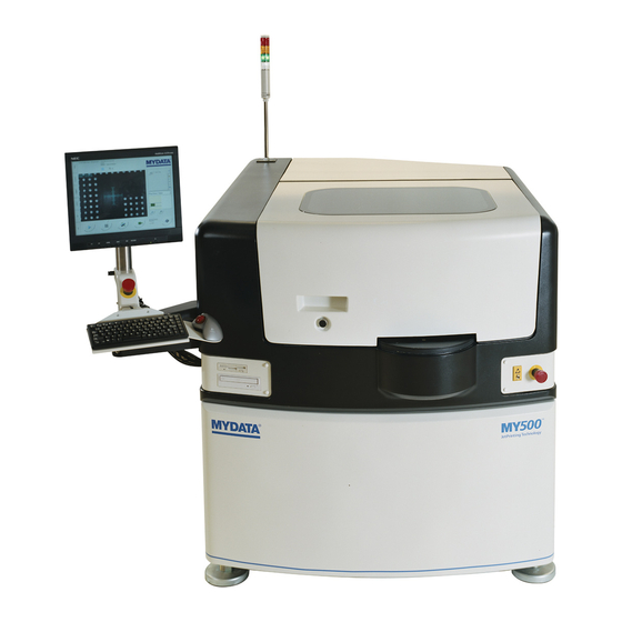
- Page 1 MY500 JetPrinter™ Service Manual English P-030-0014-EN ® For a fast changing world...
- Page 3 MYDATA MY500 JetPrinter Preface MY500 JetPrinter™ Service Manual English P-030-0014-EN – Service Manual Rev. 0003 2008-06...
- Page 4 MYDATA and its suppliers shall not be liable for any damages related to this software or hardware, or for any other damages whatsoever caused by the use of or inability to use any MYDATA product. This is applicable even if MYDATA has been advised of the damage risk. Under any circumstances, MYDATA’s entire liability shall be limited to replace such defective software or hardware that was originally purchased from MYDATA.
-
Page 5: Table Of Contents
MYDATA MY500 JetPrinter Preface Table of Contents ext Conventions ......................vi Danger, Warning, Caution, and Note ..............vi Italic Font ......................vii Bold Font ......................vii Menu Selections ....................vii Lists ........................vii . Safety ........................1-1 Emergency Stop Buttons ..................1-2 Emergency Movement of Machine Elements ............ - Page 6 Software Installation ................... 2-22 Optional Equipment ................... 2-22 . Machine Systems ....................... 3-1 MY500 JetPrinter ....................3-1 Jet Printing ....................3-1 MY500 JetPrinter Main Parts ................3-2 Inputs and Controls .................... 3-4 Touch Screen ....................3-4 Keyboard ....................... 3-5 Trackball ......................3-5 Barcode Scanner ....................
- Page 7 MYDATA MY500 JetPrinter Preface ppendix A – Specifications ..................A-1 ppendix B – About the Documentation ..............B-1 Operator's Manual ....................B-2 Programming Manual ..................B-2 MYCamJP ......................B-2 Service Manual ....................B-3 Spare Parts Catalog .................... B-3 ndex ..........................I-1 P-030-0014-EN –...
-
Page 8: Text Conventions
MYDATA Preface MY500 JetPrinter Text Conventions This document uses text conventions to present information in various situations. This is explained below. Danger, Warning, Caution, and Note In this document a particular text layout is used to make danger, warning, and caution information evident. -
Page 9: Italic Font
MYDATA MY500 JetPrinter Preface Italic Font Italic font is used for software screen text (for example Parameter 1), names (for example Spare Parts Catalog), and for warning text (described in the previous section). Bold Font Bold font is used for particular important words (for example This must not be done in reverse order). - Page 10 MYDATA Preface MY500 JetPrinter viii P-030-0014-EN – Service Manual Rev. 0003 2008-06...
-
Page 11: Safety
• Do not disable or disengage any safety switch or sensor. • Do not configure or modify MYDATA machines or devices without consulting MYDATA. The machines, devices or the interfaces between them might become unsafe. •... -
Page 12: Emergency Stop Buttons
Emergency stop buttons are released by being turned clockwise. When the front hood is lifted, a safety switch is activated and all movements in the MY500 JetPrinter are stopped immediately. Extra, auxiliary safety buttons can be connected at the rear of the machine. -
Page 13: Emergency Movement Of Machine Elements
MYDATA MY500 JetPrinter Safety Emergency Movement of Machine Elements If an accident has occurred and an emergency movement of a machine element is required, use the following procedure: 1. Press down an emergency stop button. This will disconnect the motors used to position the machine elements. -
Page 14: Warning Signs
MYDATA Safety MY500 JetPrinter Warning Signs The warning signs on the machine must be observed as this machine contains fast moving parts, magnetic fields, and high voltage. The machine has warning signs placed as shown on the following pages. At least one manual that describes the warning signs of the particular machine type must always be kept, for instance if the machine is upgraded with a later TPSys version. - Page 15 MYDATA MY500 JetPrinter Safety Figure 1-4. Warning sign on the machine’s left side hood. Figure 1-5. Warning signs on the machine’s right side hood. 1 - 5 P-030-0014-EN – Service Manual Rev. 0003 2008-06...
-
Page 16: Dangerous Voltage
MYDATA Safety MY500 JetPrinter Dangerous Voltage These signs warns of electric shock. Units on which this sign is placed contain dangerous voltage levels. Power must be switched off before opening the unit. Only authorized service personnel are allowed to operate the machine when such a unit is open. -
Page 17: Laser Classification
MY500 JetPrinter Safety Figure 1-7. Warning sign at the connection plate inside. Laser Classification Sign 3 states the laser classification for the MY500 JetPrinter. One certification sign is applied as shown in Figure 1-6. 1 - 7 P-030-0014-EN – Service Manual... -
Page 18: Magnetic Fields
MYDATA Safety MY500 JetPrinter Magnetic Fields European and US standards Canadian standards Sign 4 warns for magnetic fields. One warning sign is applied as shown in Figure 1-8. Figure 1-8. Warning signs inside the machine. 1 - 8 P-030-0014-EN – Service Manual... -
Page 19: Type Plate
Figure 1-9. Machine type plate. The type plate is found at the back of the machine, see '5' in Figure 1-6. Noise For the MY500 JetPrinter, the equivalent continuous sound pressure level is measured to be 68 dB(A). 1 - 9 P-030-0014-EN –... -
Page 20: Equipment Precautions
MYDATA Safety MY500 JetPrinter Equipment Precautions This section has to be read before handling the machine. CAUTION! Always ensure that there are no foreign objects on the conveyor or within the X wagon and Y beam moving areas before operating the machine. -
Page 21: Compressed Air
MYDATA MY500 JetPrinter Safety Compressed Air This machine uses compressed air for its operation. WARNING! Compressed air can be dangerous if handled incorrectly. Assembly, handling, or repair of pneumatic systems must be performed by trained and experienced personnel. Solder Paste, Glue and Conditioner Cassettes for the machine contain solder paste, which is a mixture of powder and flux. -
Page 22: Material Safety Data Sheets
MYDATA support. Greases GREASE PASTE OKS 270, part number K-013-0014 MSDS is found at http://www.mydata.com, document number P-040- 0137-EN. A logon user name and password may be required. GREASE AFA+70 THK, part number K-035-0095 MSDS is found at http://www.mydata.com, document number P-035- 0095-EN. -
Page 23: In Case Of Fire
If it is necessary, make sure that you do not touch pins or printed conductors. All MYDATA machines have jacks for wrist straps. They are marked with an ESD sign. 1 - 13 P-030-0014-EN –... - Page 24 MYDATA Safety MY500 JetPrinter 1 - 14 P-030-0014-EN – Service Manual Rev. 0003 2008-06...
-
Page 25: Installation
MYDATA MY500 JetPrinter Installation Installation In this chapter you will find the following information: – Site Preparation on page 2-2. Describes what is required of the site for a successful installation. – Installation on page 2-7. Describes how to install the machine at the site. There is also site preparation check list on page 2-22. -
Page 26: Site Preparation
Site Preparation In this section you will find prerequisites of what is required of the site for a successful installation of a MYDATA MY500 JetPrinter. Details about the working area, environmental and electrical requirements, and regulatory compliance are given. Follow these directions to ensure a safe and proper installation, as well as ongoing operating efficiency. - Page 27 One cable, 1 m of length, for the connection of the offline station to a gateway. One cable, 30 m of length, for the connection of the MY500 JetPrinter. CAUTION! Always make sure that the way cables and tubes are placed do not present a hazard.
- Page 28 MYDATA Installation MY500 JetPrinter 1070 Bottom view Figure 2-2. Machine footprint. Power, network and compressed air in. 1 000 mm 1 000 mm 1 000 mm Figure 2-3. Clear space required around the machine. 2 - 4 P-030-0014-EN – Service Manual...
-
Page 29: Environmental Requirements
<95 %, non-condensing Storage: 100 % Altitude The MY500 JetPrinter is capable to operate correctly at altitudes up to 1 000 m above mean sea level. Dust and dirt The machine does not require a clean-room environment but dust and dirt must be kept as low as possible. -
Page 30: Electrical Requirements
MYDATA Installation MY500 JetPrinter Electrical Requirements Always follow the existing local, national or international regulations when installing this equipment. Acceptable voltages (±10 %): 230/115 VAC. Compressed Air The pneumatic system in the machine requires compressed air. Minimum pressure required is 7 bar, maximum allowed is 10 bar. -
Page 31: Installation
MYDATA MY500 JetPrinter Installation Installation Upon arrival the machine must be unpacked, lifted, moved to the machine site and leveled. This section describes how to perform the installation tasks and is divided into the following main parts: – Unpacking on page 2-9. -
Page 32: Installation Summary
Installation MY500 JetPrinter Installation Summary This is a summary of the installation process of a MY500 JetPrinter: – Unpack the machine and all other packages. – Check the ’Shock Watch’ and ’Tilt Watch’ gages. – Check that all ordered parts are delivered. -
Page 33: Unpacking
Unpacking The machine is shipped in a wooden crate (outside Europe) and must be handled with care. It is strongly recommended that a MYDATA representative is present when the machine is unpacked. 1. Inspect the ’Shock Watch’ and ’Tilt Watch’ gages for activation and the crate for damages. -
Page 34: Lifting The Machine
MYDATA Installation MY500 JetPrinter Lifting the Machine To avoid tilting or damaging the machine, always lift the machine as described below. The description includes fork lift as well as crane lift. The machine weighs 2 000 kg net. WARNING! Lift the machine as described below. Otherwise, the machine may become damaged and the lifting may become dangerous. - Page 35 Installation Crane lift We recommend using four flat webbing slings to lift the MY500 JetPrinter with a crane. They are slung around the leveling feet of the machine. The slings must be able to carry 1.6 tons each when snared. This is indicated on the label on the sling, see Figure 2-6.
-
Page 36: Moving And Placing The Machine
MYDATA Installation MY500 JetPrinter Moving and Placing the Machine Move the machine to the final position and put it on the leveling feet. You can use either a fork lift or a crane. CAUTION! Always ensure that the transport lock is attached before moving the machine. -
Page 37: Main Machine Connections
MYDATA MY500 JetPrinter Installation Main Machine Connections The main connection points are found on the back of the machine. These points are placed on the outside of the connection plate (the lower door). This door can only be unlocked by a special key, which is provided with the machine. -
Page 38: Powering
Installation MY500 JetPrinter Powering MYDATA machines are set up for adequate mains supply before delivery according to the customer order. This means, that normally only the mains power needs to be connected without alterations inside the machine. Knowing your mains power supply, you can verify that the machine is properly set up by reading on the type label. -
Page 39: Electrical Connection
MYDATA MY500 JetPrinter Installation Electrical Connection This machine is intended to be stationary and movable to accommodate the changing production needs of the end use factory (this is in compliance with the NEC Article 400-7 and -8). Power Plug Connection The machine mains transformer is connected by the mains power cord shown in Figure 2-10. -
Page 40: Pneumatic Connection
7 bar. The pressure hose is connected to the regulator on the backside of the machine. Figure 2-13. Pneumatic valve on the MY500 JetPrinter. There are two optional pneumatic air units available for installation – the air cooling unit and the micro mist unit. -
Page 41: Optional Air Cooling Unit
MY500 JetPrinter. CAUTION! Do not use any other tube than L-030-0045, to connect the Cooling Unit with the MY500 JetPrinter. This because the MY500 JetPrinter need both dried and cooled compressed air. Electric connection Connect the electrical cable to an grounded outlet with a voltage of: –... -
Page 42: Optional Micro Mist Separator Unit
The Cooling Unit must have a minimum distance of 0.4 m to nearest wall or machine. Optional Micro Mist Separator Unit Air in To MY500 JetPrinter Figure 2-15. Micro mist separator unit. Connect ’Air in’ of the Micro Mist Separator Unit to compressed air 0.8– 1.0 Mpa. -
Page 43: Network Connection
MY500 JetPrinter is handled by SMEMA-standardized connectors. The MY500 JetPrinter connection plate have are two SMEMA connectors – SMEMA OUT and SMEMA IN. An external equipment’s SMEMA IN is connected to the MY500 JetPrinter SMEMA OUT. SMEMA IN on the MY500 JetPrinter is connected to the SMEMA OUT on the external equipment. -
Page 44: Transport Lock
MYDATA Installation MY500 JetPrinter Transport Lock CAUTION! Always remove the transport lock before powering up the machine for the first time! The Y beam and X wagon are locked in position during transport. These locks must be removed before starting the machine. - Page 45 MYDATA MY500 JetPrinter Installation 2. Pull the Y beam slighltly forward, and remove the lock, see 2-18. Figure 2-18. Transport lock. The lock is placed behind the bottom magnet on the Y beam, but in frot of the conveyor. Figure 2-19. Transport lock.
-
Page 46: Software Installation
MYDATA Installation MY500 JetPrinter Software Installation When the machine has arrived at its location in the workshop, it is time to do software installation procedures. These procedures are described in a separate installation guide. Optional Equipment Optional equipment, like for instance the manual load table, are provided with their own installation guides. -
Page 47: Machine Systems
Machine Systems This chapter contains brief descriptions of the various systems that make up the MY500 JetPrinter machine. The object is to give an orientation rather than an in-depth understanding of the systems. At the end of the chapter you will find block diagrams. -
Page 48: My500 Jetprinter Main Parts
MYDATA Machine Systems MY500 JetPrinter MY500 JetPrinter Main Parts Figure 3-1. MY500 JetPrinter, components on the outside. Outside: 1. Main switch. 2. Emergency stop buttons. 3. Touch screen. 4. Keyboard 5. Trackball 6. Front hood. 7. Front hood handle. 8. Light tower (optional). - Page 49 MYDATA MY500 JetPrinter Machine Systems Figure 3-2. MY500 JetPrinter, components on the inside. Inside: 12. Y beam. 13. X wagon. 14. Solder paste cassette. 15. Camera calibration unit. 16. Cassette calibration unit. 17. Internal conveyor. 18. Electric cable harness. 3 - 3 P-030-0014-EN –...
-
Page 50: Inputs And Controls
Touch Screen You can operate the MY500 JetPrinter machine by using the LCD (liquid crystal display) touch screen. Functions such as start, stop, toggle and so on are triggered when you touch the designated buttons on the screen with your finger. -
Page 51: Keyboard
Machine Systems Keyboard A keyboard is provided with the MY500 JetPrinter. It acts as the standard input tool for the JPSys software. It can also control the system in a normal Windows way if so desired. For more information on how to use a keyboard to control Windows we refer you to the Microsoft Windows help or user’s... -
Page 52: Framework
MYDATA Machine Systems MY500 JetPrinter Framework To be able to withstand high stresses, from accelerating movements, the frame of the printer is made in a heavy stone-epoxy composite material. This is a mineral casting mixed with epoxy. Mineral casting have outstanding dampening, high rigidity and ensure dimensional accuracy. -
Page 53: Movement Systems
MYDATA MY500 JetPrinter Machine Systems Movement Systems The movement system is a three-dimensional system, based upon a carbon fiber beam and two wagons. The motion system operates together with an optic positioning system. The machine contains the following movement systems: •... -
Page 54: The Y Beam
MYDATA Machine Systems MY500 JetPrinter The Y Beam The Y beam is a carbon fiber epoxy structure. This material has an advantageous combination of good mechanical properties and low weight. It is used for very stiff and light structures within sports equipment, aerospace, and medical equipment. -
Page 55: The X Wagon
MYDATA MY500 JetPrinter Machine Systems The X Wagon On the Y beam the X wagon is attached, which generates the X movements. On the X wagon there is a solder paste cassette interface and a positioning camera. Figure 3-8. X wagon. - Page 56 MYDATA Machine Systems MY500 JetPrinter The X wagons positioning accuracy is, like the Y beam's, governed by a linear encoder system. The linear scale for the X wagon is located on the Y beam. Figure 3-10. X wagon linear scale.
- Page 57 MYDATA MY500 JetPrinter Machine Systems Cassette interface Figure 3-12. Cassette interface main parts. The cassette interface is divided into the following main parts: 1. Attachment unit. 2. Motor unit. Attachment unit Figure 3-13. Attachment unit main parts. 1. Attach claw.
-
Page 58: Motor Unit
MYDATA Machine Systems MY500 JetPrinter Motor unit Figure 3-14. Motor unit main parts. 1. Motor unit. 2. Sleigh unit. 3 - 12 P-030-0014-EN – Service Manual Rev. 0003 2008-06... -
Page 59: The Cassette
MYDATA MY500 JetPrinter Machine Systems The Cassette The solder paste cassette is made up of a holder with a motor assembly and a paste cartridge. Figure 3-15. Solder paste cassette. On the backside of the holder you will find a circuit board which connects the cassette and machine. - Page 60 MYDATA Machine Systems MY500 JetPrinter The holder assembly The holder assembly is the carrier of the solder paste cartridge and the interface between the machine and the cartridge. It carries the ejector assembly and the motor unit. Figure 3-16. Holder.
- Page 61 MYDATA MY500 JetPrinter Machine Systems The ejector The ejector is a wear part. It requires no internal cleaning or disassembling. The ejector carry the piezo unit which generates the force needed to eject the solder paste through the ejectors nozzle.
- Page 62 MYDATA Machine Systems MY500 JetPrinter Figure 3-18. Filter box. The main parts of the filter box are: 1. Lid 2. Box 3. Suction cups. WARNING! Solder paste, during handling or use, may be hazardous to health or the environment. Read the Material Safety Data Sheet and warning label before using.
- Page 63 MYDATA MY500 JetPrinter Machine Systems The solder paste cartridge The solder paste cartridge is a disposable container that is discarded after use. Figure 3-19. Solder paste cartridge. It has the following main parts at delivery: 1. Cap (removed when installed into the holder). Used for transport and storage when not in holder.
-
Page 64: Conveyor
MYDATA Machine Systems MY500 JetPrinter Conveyor The board is transported into and out of the machine by an internal conveyor. This is a top reference conveyor which accept cards with the following specifications: – Maximum PWB width and length: 508 × 508 mm. -
Page 65: Manual Load Table
Manual Load Table The intention is that the internal conveyor is connected to an external conveyor system. As an option MYDATA have a manual load table for the cases where an external conveyor system is not available. Figure 3-21. Manual load table. -
Page 66: Machine Electronics
MYDATA Machine Systems MY500 JetPrinter Machine Electronics The following amplifier and control units are found in the machine behind the front hood. Block diagrams describing these units are found in the next section. Figure 3-22. Machine electronic units. Units: 1. PC Runs the JPSys machine software. - Page 67 MYDATA MY500 JetPrinter Machine Systems 5. MOT–CTRL Safety module which monitors the safety loop, and controls the X and Y motor, conveyor, piezo drive, laser and stepper motor. External safety switches can be added to the AUX EMERG connector on the back of the machine.
-
Page 68: Block Diagrams
MYDATA Machine Systems MY500 JetPrinter Block Diagrams Below you will find block diagrams for the MY500 JetPrinter. ZG-031-0046 This diagram provides an overview of the connection plate on the back of the machine. ZG-030-0013 This block diagram provides an overview of the electronic, safety and pneumatic system. - Page 69 MYDATA MY500 JetPrinter Machine Systems This document is our property. It must not be copied and its contents must not be imparted to third persons without our written permission. Infringement of the above will be prosecuted. 10AT (x2) Safety Relay...
- Page 70 MYDATA Machine Systems MY500 JetPrinter This document is our property. It must not be copied and its contents must not be imparted to third persons without our written permission. Infringement of the above will be prosecuted. +24V RUE250 MMI - module...
- Page 71 MYDATA MY500 JetPrinter Machine Systems This document is our property. It must not be copied and its contents must not be imparted to third persons without our written permission. Infringement of the above will be prosecuted. LINE LOAD LINE LINE...
- Page 72 MYDATA Machine Systems MY500 JetPrinter This document is our property. It must not be copied and its contents must not be imparted to third persons without our written permission. Infringement of the above will be prosecuted. 3 - 26 P-030-0014-EN – Service Manual...
- Page 73 MYDATA MY500 JetPrinter Machine Systems This document is our property. It must not be copied and its contents must not be imparted to third persons without our written permission. Infringement of the above will be prosecuted. AMP X AMP Y...
- Page 74 MYDATA Machine Systems MY500 JetPrinter This document is our property. It must not be copied and its contents must not be imparted to third persons without our written permission. Infringement of the above will be prosecuted. CABLECHAIN 3 - 28 P-030-0014-EN –...
- Page 75 MYDATA MY500 JetPrinter Machine Systems 3 - 29 P-030-0014-EN – Service Manual Rev. 0003 2008-06...
- Page 76 MYDATA Machine Systems MY500 JetPrinter 3 - 30 P-030-0014-EN – Service Manual Rev. 0003 2008-06...
-
Page 77: Adjustments
MYDATA MY500 JetPrinter Adjustments Adjustments The JPSys system includes a service system. This is a tool used to calibrate and adjust the machine systems. In this manual we will not describe the service system. This chapter is only a brief orientation. -
Page 78: System Overview
MYDATA Adjustments MY500 JetPrinter System Overview When you start the service system you will get a system overview, see Figure 4-2. You are shown information about the machine and its software. In a listing to the left you can select the systems you would like to test. -
Page 79: Screen Examples
MYDATA MY500 JetPrinter Adjustments Screen Examples The system is self-instructing. The initial screens are overview screens with a brief description, and information, of the system. The following screens are used to test and calibrate system and hardware. In the hardware window manual adjustments can be made. - Page 80 MYDATA Adjustments MY500 JetPrinter Figure 4-4. The movement system test screen. Figure 4-5. The movement system hardware screen. 4 - 4 P-030-0014-EN – Service Manual Rev. 0003 2008-06...
-
Page 81: Routine Maintenance
MYDATA MY500 JetPrinter Routine Maintenance Routine Maintenance This chapter informs about preventive maintenance for the MY500 JetPrinter. The described maintenance should be performed at stated intervals. The warranty on the machine and parts applies only if these instructions are followed. - Page 82 MYDATA Routine Maintenance MY500 JetPrinter Maintenance intervals The intervals for daily and weekly maintenance are fixed. All other maintenance intervals are dependent on the usage of the machine. CAUTION! The maintenance intervals apply to a clean environment and an indoor temperature of maximum 25°C.
-
Page 83: Daily Maintenance
MYDATA MY500 JetPrinter Routine Maintenance Daily Maintenance Equipment – Lint-free cotton wool buds. – Lint-free cloths. Cassette – Check the guide pins on the holder for wear or damage. If the guide pins are damaged, replace the holder. – Wipe off any solder paste or dirt from the holder´s backside with a lint-free cloth. -
Page 84: Machine
MYDATA Routine Maintenance MY500 JetPrinter Machine WARNING! Before commencing, press an emergency stop button down. – Inspect the Cassette interface. Wipe off any solder paste using a lint- free cloth. Be careful with the connector surfaces. Cassette interface Figure 5-3. Cassette interface. -
Page 85: Calibration Units
Figure 5-5. Calibration unit. – Check if the waste container (B) is getting full. Replace the waste container if necessary, see the MY500 JetPrinter, Service Manual. – Check the quantity of paper (C). Reload if there is a red line on the paper´s side, see the MY500 JetPrinter, Service Manual. -
Page 86: Filters
MYDATA Routine Maintenance MY500 JetPrinter Filters The air filter indicator (’A’ in the figure) is located on one of the two air filters. Figure 5-7. Air filter indicator. If the machine is equipped with an optional Refrigerated Air Dryer unit, the air filters are located on that unit. -
Page 87: Weekly Maintenance
MYDATA MY500 JetPrinter Routine Maintenance Weekly Maintenance This preventive maintenance shall only be carried out by authorized service engineers. Equipment – Lint-free cloths. WARNING! Before commencing, switch the power off, and lock out and tag the main switch. -
Page 88: Others
Do not use abrasives or cleaning solutions! – Warning signs on the machine must be clean and readable. If needed, clean or replace the signs (refer to the MY500 JetPrinter, Operator’s Manual). 5 - 8 P-030-0014-EN – Service Manual... -
Page 89: Monthly Maintenance
MYDATA MY500 JetPrinter Routine Maintenance Monthly Maintenance This preventive maintenance shall only be carried out by authorized service engineers. Equipment – Lint-free cloths. – Vacuum cleaner or blow nozzle. Machine – Remove dust from the ventilation areas on the top back hood. -
Page 90: Yearly Maintenance
MYDATA service engineers. There is a specific instruction for the yearly maintenance that has to be followed. Please contact your MYDATA Service Department to arrange for a visit by a MYDATA field service engineer. This service will affect for example: –... -
Page 91: Changing Calibration Paper
MYDATA MY500 JetPrinter Routine Maintenance Changing Calibration Paper This preventive maintenance shall only be carried out by authorized service engineers. WARNING! Before commencing, switch the power off, and lock out and tag the main switch. The solder paste cassette is calibrated every time you change it or initiate the hardware. - Page 92 MYDATA Routine Maintenance MY500 JetPrinter 1. Remove the empty roll and spent paper. 2. Push a new paper roll onto the first shaft and place it in the holder. Feed the paper into the slot in the paper guide and pull it through.
- Page 93 MYDATA MY500 JetPrinter Routine Maintenance 3. On the other side of the paper guide, push the paper into the feeder shaft slot. Roll the wheel to secure the paper to the wheel. 5 - 13 P-030-0014-EN – Service Manual Rev. 0003 2008-06...
-
Page 94: Changing Waste Container
MYDATA Routine Maintenance MY500 JetPrinter Changing Waste Container When you use the Purge button, the cassette will do ’dummy’ shots into a waste container on the cassette calibration unit. Check the container regularly. Change if the container is 2/3 full, otherwise solder paste may splash outside of the container when purging. -
Page 95: Changing Cassette Ejector
MYDATA MY500 JetPrinter Routine Maintenance Changing Cassette Ejector An ejector, at the bottom of the holder, carries the piezo unit and a nozzle. The piezo unit generates the force needed to eject the solder paste through the nozzle. This ejector is good for 30 solder paste cartridges. After that it must be changed. - Page 96 MYDATA Routine Maintenance MY500 JetPrinter 3. Tilt the ejector up-wards slightly. Figure 5-13. Tilting the ejector. 4. Pull the ejector out from the holder to the left. Figure 5-14. Pulling the ejector out. 5. Lift the ejector away from the holder.
- Page 97 MYDATA MY500 JetPrinter Routine Maintenance 6. Remove the two yellow, protective plastic caps. Slip a the ejector into the holder from the left. Push it onto the pin, see Figure 5-16. Figure 5-16. Slipping the ejector into the holder. 7. Push down and swing the motor back in place. Re-tighten the two torx- screws which you loosened in step 1, see Figure 5-11.
- Page 98 MYDATA Routine Maintenance MY500 JetPrinter Be careful not to loose the spring, highlighted in Figure 5-18, when you take a new ejector out of its packing. Figure 5-18. Ejector spring. In a new ejector there is a conditioner that must be removed before it can used in production.
-
Page 99: Lubricating X Wagon Rail - 720 Operating Hours
Figure 5-19. X-wagon rail and bearings. Equipment – Grease gun from the spare parts kit. – AFA lubricant, MYDATA part number K-035-0095. Performing 1. Turn off the power, and lock and tag the main switch. 2. Open the machine front hood. -
Page 100: Testing The Safety System
MYDATA Routine Maintenance MY500 JetPrinter Testing the Safety System This maintenance shall only be carried out by authorized service engineers. The safety system should be tested at regular intervals. WARNING! Ensure no hands, fingers, or other objects are entered within the shielded area before the machine has stopped. -
Page 101: Maintenance Tables
MYDATA MY500 JetPrinter Routine Maintenance Maintenance Tables This section shows the previous described maintenance as tables that can be copied and used as service protocols. Daily Maintenance Place Maintenance action Completed Cassette – Inspect the cassette holder for wear or damage. -
Page 102: Monthly Maintenance
MYDATA Routine Maintenance MY500 JetPrinter Monthly Maintenance Place Maintenance action Completed Machine Clean the ventilation areas. Refrigerated Air Clean ventilation area, and check connections and tubing. Dryer (optional) 720 Operating Hours Place Maintenance action Completed X-wagon rail and Lubricate x-wagon rail and bearings. -
Page 103: Appendix A - Specifications
MYDATA MY500 JetPrinter Appendix A – Specifications Appendix A – Specifications Length Width Height These specifications can be changed at any time without prior notice. For updated data, please contact your MYDATA representative. Machine data Weight 2 000 kg. Noise 68 dB(A). - Page 104 MYDATA Appendix A – Specifications MY500 JetPrinter A - 2 P-030-0014-EN – Service Manual Rev. 0003 2008-06...
-
Page 105: Appendix B - About The Documentation
MYDATA MY500 JetPrinter Appendix B – About the Documentation Appendix B – About the Documentation The documentation of the MYDATA machines comprises the following parts: • Operator’s manual. • Programming manual. • Service manual. • Spare parts catalog. These documents are described on the following pages. -
Page 106: Operator's Manual
MYDATA Appendix B – About the Documentation MY500 JetPrinter Operator's Manual An operator’s manual is available for the MY500 JetPrintert machines. This manual is provided with each machine. The operator’s manual is available in the same languages as the JPSys software. -
Page 107: Service Manual
Spare Parts Catalog A spare parts catalog, containing information, figures and part numbers on the most common spare and consumable parts, is available from MYDATA. The spare parts catalog is available in English only. Spare Parts... - Page 108 MYDATA Appendix B – About the Documentation MY500 JetPrinter P-030-0014-EN – Service Manual Rev. 0003 2008-06...
-
Page 109: Index
MYDATA MY500 JetPrinter Index Index Cassette ....................... 3-11 attachment unit ........................3-15 ejector ....................... 3-15 filter box ...................... 3-14 holder assembly ....................... 3-11 interface ......................3-12 motor unit ....................3-17 solder paste cartridge ......................3-11 Cassette interface ......................... 3-21 CTRL-HIP ....................... - Page 110 MYDATA Index MY500 JetPrinter ........................3-3 inside ........................3-2 outside ....................3-17 solder paste cartridge ....................... 3-10 X wagon ....................... 3-21 MOT-CTRL ........................3-20 MOT-PIM .......................... 3-1 Piezo ........................1-11 Recykling Site preparation ......................... 2-2 check list ..................... 3-17 Solder paste cartridge X wagon .......................
- Page 112 Tel: + 81 3 3661 7714 Fax: + 81 3 3661 7715 MYDATA automation Ltd. CHINA 14 Wessex Trade Centre MYDATA automation Pte Ltd. Ringwood Road Block 4, No. 700 Gui Ping Road, Poole BH12 3PQ Cao He Jing Hi-Tech Park,...
Need help?
Do you have a question about the MY500 JetPrinter and is the answer not in the manual?
Questions and answers