Table of Contents
Advertisement
Advertisement
Table of Contents

Summary of Contents for JAT ECOSTEP 54
- Page 1 User Manual ECOSTEP®54...
- Page 3 Januar 2013 Revision: remarks of UL file review Oct. 2013 Revision: motor connection, limit switches supply Jan. 2014 Correction chapter 7.2 July 2014 Power supply chapter 6.3.2: Important note added Sep. 2016 JAT-Logo new All rights reserved: Jenaer Antriebstechnik GmbH Buchaer Straße 1...
- Page 4 User Manual ECOSTEP®54 Subject to change without notice!
-
Page 5: Table Of Contents
User Manual ECOSTEP®54 Inhalt About this manual ............................7 Safety instructions ............................7 Symbols ................................. 7 General notes ..............................8 Dangerous voltages ............................8 Danger by hot surfaces ..........................8 Danger by unintentional mechanical movements ................... 8 Prescribed use ............................... 9 Legal notes..............................9 Terms of delivery ............................ - Page 6 User Manual ECOSTEP®54 Accessories ..............................38 Supplementary parts ............................ 38 8.1.1 Heat sink ................................ 38 Annex ................................39 Flowcharts for PLC programming ......................39 9.1.1 Homing ................................39 9.1.2 Operation mode 1 (Profile Positioning Mode): Direct absolute positioning (effective immediately) ..........................40 9.1.3 Operation mode 1 (Profile Positioning Mode): Absolute positioning after setting the control word ............................
-
Page 7: About This Manual
User Manual ECOSTEP®54 About this manual This user manual describes the stepper amplifier series ECOSTEP®54. It concerns all persons who install, commission and operate ECOSTEP®54 drives. Further information: Operation using ECO Studio: „ECO Studio Operation Manual ECOVARIO®, ECOSTEP®, ECOMPACT®“ Programming: manual „Object Dictionary ECOVARIO®, ECOSTEP®, ECOMPACT®“ Motor data: Data sheets series 17S and 23S (stepper motors). -
Page 8: General Notes
User Manual ECOSTEP®54 General notes Only properly qualified personnel are permitted to perform activities such as transport, in- stallation, commissioning and maintenance of the ECOSTEP®54. The manufacturer of the machine must generate a hazard analysis for the machine and take appropriate measures to ensure that unforeseen movements cannot cause injury or damage to any person or property. -
Page 9: Prescribed Use
User Manual ECOSTEP®54 Prescribed use The stepper motor amplifiers ECOSTEP®54 are components which are built into electrical equip- ment or machines and can only be used as integral components of such equipment. All notes about technical data and ambient conditions have to be observed. The device is suitable for pollution degree 2 environment only. -
Page 10: Liability
ECOSTEP54 complies to the standards and directives listet in the appendix, chapter 9.4. 3.3.1 UL/CSA compliance The stepper motor amplifiers ECOSTEP 54 are designed in compliance with UL (Underwriters Laboratories Inc.) or cUL respectively (UL 840 and UL 508C in this case). For further information see UL file number E244038 at www.ul.com. - Page 11 User Manual ECOSTEP®54 Subject to change without notice!
-
Page 12: Technical Data
User Manual ECOSTEP®54 Technical Data Technical data of the power stage Table 4.1: Technical data of the power stage Number of motor outputs Max. phase currrent Step resolution Steps/rev. 12,800 Max. output voltage , cf. table 4.2 DC-BUS Max. output power 4 x 100 Short-circuit strength of motor output current limiting in case of short circuit of motor... -
Page 13: General Technical Data
17S und 23S of Jenaer Antriebstechnik GmbH. Technical data and regulations in this manual only refer to these motors. Technical data of the motors can be retrieved from the motor data sheets or from our homepage www.jat-gmbh.de. Subject to change without notice! -
Page 14: Installation
User Manual ECOSTEP®54 Installation Mounting 5.1.1 Important notes  Make sure that transport and storage did no damage to the units.  The ambient air must not be polluted by dust, greases, aggressive gas etc. Eventually appropri- ate countermeasures have to be taken (installation of filters, frequent cleaning). Â... -
Page 15: Assembly
User Manual ECOSTEP®54 5.1.3 Assembly When mounting the ECOSTEP®54 into the cabinet cable clamps (contained in connector kit AMK40, cf. chap. 8) assure that the connecting cables are laid EMC conform by connecting the cable shield extensively to chassis earth. Maximum cable diameter is 15 mm. It is important that the air flow is not disturbed by components above or below the stepper motor ampli- fiers. -
Page 16: Electrical Installation
User Manual ECOSTEP®54 Electrical Installation 5.2.1 Important notes All installation work may only be carried out if the machine or plant is not live and protected against restart. Never exceed the maximum rated voltage at the connector X11 (power supply) X11! U = 45V Stepper motor amplifier and motor have to be properly grounded. -
Page 17: Interfaces
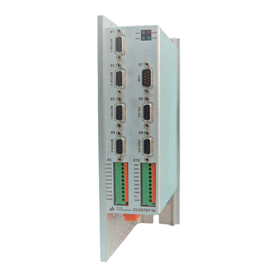
User Manual ECOSTEP®54 Interfaces Arrangement of the interfaces X1 - X4: Stepper motor connector 1 ... 4 Status LEDs X7: CAN interface X8: RS232 interface X9: Analog inputs/outputs X5: Digital outputs X10: Digital inputs X11: Power supply Fig. 6.1: Arrangement of the ECOSTEP®54 interfaces A mating connector for interface X11 (socket connector 6-pole, WAGO type 231-306) is contained in the connector kit SMK40 (siehe Kap. -
Page 18: Control Signals
Load res. 3 OUT3 Load res. +24 V 8 OUT8 Load res. +24 V +24 V Galvanic +24 V External isolation power supply 24 V ECOSTEP 54 Fig. 6.3: Connector X5: Circuit of the digital outputs Subject to change without notice! -
Page 19: X10: Digital Inputs
Control signal IGND DIN2 Control signal IGND DIN3 Control signal IGND DIN8 Control signal IGND IGND n.c. Galvanic External isolation power supply IGND 24V= ECOSTEP 54 Fig. 6.5: Connector X10: Circuit of the digital inputs Subject to change without notice! -
Page 20: X9: Analog Inputs, Analog Output
View of the solder or crimp side n.c. n.c. Analog output +/- 10 V Internal GND Control Power supply 880k 0...5V Analog value 220k ECOSTEP 54 Fig. 6.7: Connector X9: Circuit of the analog inputs and the analog output Subject to change without notice! -
Page 21: Power Connection
User Manual ECOSTEP®54 Power connection 6.3.1 X1 to X4: Motor connector Table 6.4: Pin assignment connectors X1 to X4 Signal Description Phase A Stepper motor connection Phase /A Stepper motor connection Phase B Stepper motor connection Phase /B Stepper motor connection Fig. -
Page 22: X11: Supply Voltage
User Manual ECOSTEP®54 6.3.2 X11: Supply voltage Table 6.5: Pin assignment connector X11 Signal Description 24 V logic supply +24V Incoming supply voltage +20 ... 30V max. 0.2 A GND for logic supply DC link relay + REL+ Switching on the DC link DC link relay - REL - Switching on the DC link... -
Page 23: X8: Rs232 Interface
View of the solder or crimp side n.c. n.c. n.c. shroud Shield connected to GND via housing PC COM ECOSTEP 54 X8 D-Sub 9-pole male 1:1 cabling D-Sub 9-pole female from transmitter to receiver Fig. 6.13: Lines necessary for RS232 communication The communication protocol provides network operation of up to 15 ECOSTEP®54 devices working as... -
Page 24: X7: Can Interface
User Manual ECOSTEP®54 X7: CAN interface Die CAN interface of the ECOSTEP®54 is based on the communication profile CiA DS 301 and the device profile CiA DSP 402 (drives and motion control). It must be supplied with an external voltage. Terminating resistors for busses are not built in the ECOSTEP®54. -
Page 25: Commissioning
User Manual ECOSTEP®54 Commissioning Notes before commissioning Only qualified personnel with a broad knowlege of the fields of electrical engineering, auto- mation and drives are allowed to commission the stepper motor amplifier ECOSTEP®54. If required, Jenaer Antriebstechnik GmbH offers trainings. The manufacturer of the machine must generate a hazard analysis for the machine and take appropriate measures to ensure that unforeseen movements cannot cause injury or damage to any person or property. -
Page 26: Work Schedule Commissioning
User Manual ECOSTEP®54 Work schedule commissioning 1. Check installation The stepper motor amplifier is disconnected from the supply. Check the wiring for completeness, short cir- cuits and ground faults. For commissioning an RS232 connection via a 1:1 cable from socket X8 to COM1 or COM2 of a PC is required. - Page 27 User Manual ECOSTEP®54 Fig. 7.1: Communication: Connect/Disconnect window  ID: The device address (ID) of an ECOSTEP54 is adjusted to 1 by default and results from the sum of object „node-ID“ (Ox100B,00) and object „node-offset“ (Ox2F80,00). The ID can only be changed via the object „node-offset“...
- Page 28 User Manual ECOSTEP®54 Fig. 7.2: Parameter settings for motor and holding brake: Window „Output Mode -> Stepper Motor“ Â Maximum Current: maximum motor current -> please take from motor data sheet. Â Holding Current: phase current at standstill -> please take from motor data sheet. Â...
- Page 29 User Manual ECOSTEP®54 8. Configure limit position switches If the limit position switches at the motor connection X1 ... X4 shall not be used, the limit positions can be configured under Inputs/Outputs -> Digital Inputs. Fig. 7.3: Configuring the limit position switches in the „Digital Inputs“ window Table 7.1: Parameters and possible settings of digital inputs and limit position switches Parameter Description...
- Page 30 User Manual ECOSTEP®54 9. Configure holding brake If the holding brake shall be connected alternatively to connector X5 OUT5 ... 8, the mapping of the respec- tive output has to be set to object 0x21240020. AndMask and CmpMask specify the respective output. The settings are done under Inputs/Outputs ->...
- Page 31 User Manual ECOSTEP®54 Fig. 7.5: Control word and status word in the „Device Status“ window 13. Set „Enable Operation“ bit in the control word The drive is ready now for further commands. The drive can be switched off any time by resetting the „Ope- ration enable“...
- Page 32 User Manual ECOSTEP®54 Fig. 7.6: Homing settings The following homing parameters can be set in the window: Table 7.3: Homing parameters at ECOSTEP54 Parameter Description After homing has been finished the home position can be Zero Shift shifted with this parameter. Reference Switch Velocity of the search travel for the reference switch Search Velocity...
- Page 33 User Manual ECOSTEP®54 15. Select operation mode Besides homing the following operation modes can be selected for the ECOSTEP54 in the navigation area under Motion:  Positioning Mode  Velocity Mode. In the Positioning Mode the following parameters can be configured for the 4 controlled axes in the na- vigation area under Motion ->...
- Page 34 User Manual ECOSTEP®54 Specification of the position window (symmetrical value range around the target position). If the actual position is Position Window within the position window the „target reached“ flag is set in the status word. Limit position in positive direction, determined by the me- Positive Software chanics of the machine or by setting a positive software limit Limit Pos.
- Page 35 User Manual ECOSTEP®54 Table 7.6: Parameters in the Velocity Mode for ECOSTEP54 Parameter Description A target velocity is specified. The travel mode can be speci- fied either with velocity profile by using the acceleration and deceleration ramps (selection profile) or without velocity Target Velocity profile (selection direct) and becomes valid by clicking the Start button.
-
Page 36: Error Case
User Manual ECOSTEP®54 7.3.1 Error case If an error occurs the red „ERR“ LED on the front side of the ECOSTEP54 goes on and in the status word (Device Status) the „Fault“ bit is set. Fault conditions are evaluated individually for each axis and are displayed in the Device Errors tab at the bottom of the main window. - Page 37 User Manual ECOSTEP®54 Table 7.8: Specifying the behaviour of the drive in case of quick stop, shutdown and fault conditions Name Description Options Behaviour in case of „Quick Stop“. 0: Drive is switched off and axis coasts down, no braking ramp (default setting) Note: Default setting is the switching-off of the 1: Slow down on slow down ramp (normal braking drive in case of quick stop.
-
Page 38: Accessories
User Manual ECOSTEP®54 Accessories Table 8.1: Survey of ECOSTEP®54 accessories Order key Description Heat sink SMH41 Heat sink for ECOSTEP®54 with mounting elements Connector Kit SMK40 Socket connector 6-pole (WAGO type 231-306) as mating connector for X11 Strain relief bushing 20 mm and raised-head screw M3 x 12 (Strain relief and shield connection of the connection cables) Software tools... -
Page 39: Annex
User Manual ECOSTEP®54 Annex Flowcharts for PLC programming 9.1.1 Homing Flowchart homing for ECO54 axis, initial situation after power-on: control word = 0x0006, status word = 0x0031. For safety reasons every movement of an axis should be monitored by the PLC via timeout. Set modes_of_operation = 0x06 Start homing and timeout: control word = 0x001F... -
Page 40: Operation Mode 1 (Profile Positioning Mode): Direct Absolute Positioning (Effective Immediately)
User Manual ECOSTEP®54 9.1.2 Operation mode 1 (Profile Positioning Mode): Direct absolute positioning (effective immediately) Flowchart positioning mode absolute direct (1) after homing for ECO54 axis. Status: control word = 0x000F, status word = 0x8437 For safety reasons every movement of an axis should be monitored by the PLC via timeout. The relevant parameters profile_velocity, profile_acceleration, profile_deceleration, quick_stop_deceleration and target_position cannot be manipulated by the PLC if a mapping to other controller parameters (analog input, etc.) exists! -
Page 41: Operation Mode 1 (Profile Positioning Mode): Absolute Positioning After Setting The Control Word
User Manual ECOSTEP®54 9.1.3 Operation mode 1 (Profile Positioning Mode): Absolute positioning after setting the control word Flowchart positioning mode absolute (1) after homing for ECO54 axis 0. Status: control word = 0x000F, status word = 0x8437 For safety reasons every movement of an axis should be monitored by the PLC via timeout. The relevant parameters profile_velocity, profile_acceleration, profile_deceleration, quick_stop_deceleration and target_position cannot be manipulated by the PLC if a mapping to other controller parameters (analog input, etc.) exists! -
Page 42: Operation Mode 1 (Profile Positioning Mode): Relative Positioning
User Manual ECOSTEP®54 9.1.4 Operation mode 1 (Profile Positioning Mode): Relative positioning Flowchart positioning mode relative (1) after homing for ECO54 axis 0, Status: control word = 0x000F, status word = 0x8437 For safety reasons every movement of an axis should be monitored by the PLC via timeout. The relevant parameters profile_velocity, profile_acceleration, profile_deceleration, quick_stop_deceleration and target_position cannot be manipulated by the PLC if a mapping to other controller parameters (analog input, etc.) exists! -
Page 43: Operation Mode 3 (Profile Velocity Mode)
User Manual ECOSTEP®54 9.1.5 Operation mode 3 (Profile Velocity Mode) Flowchart velocity mode (3) for ECO54 axis, Stauts: control word = 0x0006, status word = 0x0031 For safety reasons every movement of an axis should be monitored by the PLC via timeout. The relevant parameter target_velocity cannot be manipulated by the PLC if a mapping to other controller parameters (analog input, etc.) exists! target_velocity = 0x00000000... -
Page 44: Data Protocol Of The Rs232 Interface
User Manual ECOSTEP®54 Data Protocol of the RS232 Interface Generally, the behaviour of the RS232 interface is according to the CAN standard. The CAN pro- tocol is „tunneled“, i.e., the data is transported within the CAN protocol via the serial interface. As device address the CAN Node ID is used. -
Page 45: Download Request (Data Transfer From Host To Slave)
User Manual ECOSTEP®54 Acces to the object dictionary via RS232 will work in the same way as CANopen SDO, excluding segmented data transfer. The 8 byte data of the SDO protocol are extended by 1 byte address (node ID) and 1 byte checksum. The arrangement of the 8 byte data is described in the following. Application of the PDO, SYNC, EMCY and NMT objects is not possible via RS232. -
Page 46: Upload Request (Data Transfer From Slave To Host)
User Manual ECOSTEP®54 9.2.2 Upload Request (Data Transfer from Slave to Host) Upload from not existing objects is responded with an error message. The host sends: Byte 0 Byte 1 Byte 2 Byte 3 Byte 4 Byte 5 Byte 6 Byte 7 INDEX SUBINDEX... -
Page 47: Glossary
User Manual ECOSTEP®54 Glossary Baud rate Unit of measure for the transmission rate of data in serial interfaces. The baud rate indicates the number of possible changes of state of the transmitted signal per second (1 baud = 1 state change/s). The baud rate can be lower than the bit rate (one bit is coded in several signal states). -
Page 48: Index Of Standards And Directives
User Manual ECOSTEP®54 Index of standards and directives DIN EN 954-1: Safety of machinery - Safety related parts of control systems - Part 1: general principles for design DIN EN 50170: General purpose field communication system DIN EN 50178: Electronic equipment for use in power installations DIN EN 60 204: Safety of machinery - electrical equipment of machines - Part 1: General requirements DIN EN 61 800-3: Adjustable speed electrical power drive systems - Part 3: EMC product standard inclu- ding specific test methods...
Need help?
Do you have a question about the ECOSTEP 54 and is the answer not in the manual?
Questions and answers