Table of Contents
Advertisement
Advertisement
Table of Contents

Summary of Contents for Portafill 4000T
- Page 1 4000T 4000T USER MANUAL...
- Page 2 Please contact Portafill International Ltd regarding any part of this manual that requires further clarification. This Manual is structured by different sections as noted in the Contents Page. These are to help you familiarize yourself with the Portafill 4000T and, most importantly, with the safe set-up, operating and maintenance procedures.
-
Page 3: Declaration Of Conformity
4000T Declaration of Conformity Declaration Number T 140 The undersigned representing the following supplier: Portafill International Limited, 29 Farriter Road, Cabragh, Dungannon, Co Tyrone Northern Ireland BT70 1TL Hereby declares that the following equipment: Model Portafill 4000T Type Mobile, Diesel-Hydraulic Powered Screening Machine... - Page 4 Portafill International Ltd. If, however, your only means of access is electronic, permission to print one copy is hereby granted.
-
Page 5: Table Of Contents
4000T SECTION 1 - MACHINE SAFETY ............................. 10 1.1 S ..............................10 AFETY NTRODUCTION 1.2 O .................................. 10 PERATION 1.3 M ................................10 AINTENANCE 1.4 S ................................12 IGNAL YMBOL 1.5 S ................................12 IGNAL ORDS 1.6 S .......................... 12... - Page 6 4000T SECTION 5 - MAINTENANCE ............................51 5.1 O ..................................52 YPES 5.2 M .............................. 52 AINTENANCE CHEDULES 5.2.1 Maintenance Schedule – Daily 10 Hours ......................52 5.2.2 Maintenance Schedule – Weekly 50 Hours ....................... 53 5.2.3 Maintenance Schedule – 100 Hours ........................53 5.2.4 Maintenance Schedule –...
- Page 8 4000T...
-
Page 9: Section 1 - Machine Safety
Only trained and competent personnel should operate / maintain / service mobile track While maintenance and service functions are equipment. If operating procedures are being performed, the Portafill 4000T must be unclear, contact your local distributor for shut down secured that assistance prior to operating. - Page 10 4 0 0 0 T Reading your operator's manual will help you Sections in your operator's manual are placed and others avoid personal injury or damage to in a specific order to help you understand all the machine. Information given in this manual the safety messages and learn the controls so will provide the operator with the safest and you can operate this machine safely.
-
Page 11: Signal Symbol
4000T 1.4 Signal Symbol The signal word “CAUTION” is a reminder of safety practices on or near the machine that may result in personal injury if proper precautions are not taken. This symbol means “Attention! Become 1.6 Safety Instructions and Alert! Your Safety is Involved”... -
Page 12: General Safety Considerations
Sticker Kits can be ordered directly from practices and procedures of this machine. Portafill International on request. It is recommended that you specify Machine Individuals working near or around the Model & Serial Number. -
Page 13: Safety During Maintenance Or Service
4000T ALWAYS keep the machine in good operating 1.10 Safety During Maintenance or condition. Inspect the machine each day for Service damage or defective components before operation. If necessary prevent the machine This machine has been manufactured to from being used by implementing a machine... -
Page 14: Safety When Working With Hazardous Chemicals
4 0 0 0 T ALWAYS ensure that all maintenance and 1.11 Safety When Working with service work is carried out on the machine Hazardous Chemicals whilst the machine is on firm level ground. Always ensure that the machine is secured ALWAYS handle hazardous chemicals with against sudden or unexpected movement or care. -
Page 15: Safety When Working With Batteries
4000T ALWAYS remove paint before welding or Avoid the hazard by: heating. Avoid potentially toxic fumes and Filling batteries in a well-ventilated area. dust. Hazardous fumes can be generated when paint is heated by welding, soldering, or Wearing eye protection and rubber gloves. -
Page 16: Safety During Work On Hydraulic System
4 0 0 0 T 1.14 Safety During Work on Hydraulic 1.15 Safety During Transport System ALWAYS ensure that when transporting the machine, that the vehicle being used is ALWAYS take care when working with the specified for hauling the gross weight of the hydraulic system and high-pressure fluids. -
Page 17: Safety During Machine Tracking
4000T 1.16 Safety During Machine Tracking NEVER attempt to track a machine across a slope. Doing so can cause the machine to tip Some machines are supplied with a tracked over, resulting in serious injury or death. The undercarriage. These machines can be moved machine is fitted with hydraulic brakes to about the site using a remote control. -
Page 18: Machine Layout And Location Of Emergency Stop
1.19 Interlock Switch and make sure that the door and/or feeder and in the closed or operating position. The 4000T is also fitted with two interlock switches on the main screen side door and... -
Page 19: Machine Safety Labels
4000T Interlock Switches 1.20 Machine Safety Labels These labels are fitted to the machine for Each Label is part numbered and positioned your protection, so as to highlight and identify as shown below, so if and when required your hazards, it is advised that you make routine local dealer can be contacted in order to checks on the condition of the stickers;... - Page 20 4 0 0 0 T P.006ENG P.016ENG P.008ENG P.009ENG P.018ENG P.010ENG P.027ENG P.011ENG P.029ENG P.014ENG P.036ENG...
-
Page 21: Machine Serial Plate
4000T P.038ENG P.049ENG P.040ENG 1.21 Machine Serial Plate Each machine is fitted with a serial plate, which is located inside the power pack near the starter panel – this plate will list the Serial No. / Date of Manufacture. When ordering replacement spare... -
Page 22: Section 2 - Machine Familiarisation And Technical Info
4 0 0 0 T Section 2 - Machine Familiarisation and Technical Info. 2.1 Machine Specification and Identification This Section of the Manual will help you identify the Various Controls and functions of the different Assembly Modules of the machine, and will help you identify the terminology used within the Manual and the Spare Parts Manual. -
Page 23: Specification
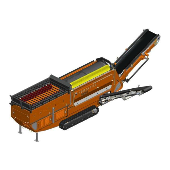
4000T Trommel Screen Reject Grid Oversize Conveyor Fines Conveyor Power Pack 2.2 Specification Feeder Conveyor 900mm wide flat belt DRUM Variable speed Removable Rotary screening drum Feeder drive sensitive to drum load Variable speed Directly driven HOPPER ... -
Page 24: Working Dimensions
4 0 0 0 T 2.3 Working Dimensions... -
Page 25: Transport Dimensions
4000T 2.4 Transport Dimensions *All drawing dimensions approximate and in millimetres. Portafill International reserves the right to alter the specification of this machine without notice. Detailed dimensional drawings can be requested directly to factory. -
Page 26: Sound Pressure Levels
4 0 0 0 T 2.5 Sound Pressure Levels The noise measurements were obtained using Measurements were taken at 1m and 5m type 1 instrumentation that was calibrated from each of the screener units. The ambient before and after use. Noise measurements noise levels were at least 10dB below the were taken in free field conditions during dry, measured noise levels when the plant was... -
Page 27: Section 3 - Application & Functions
4000T Section 3 - Application & Functions The Portafill 4000T is a hydraulically operated self-contained portable screening plant. It has been designed to withstand the rigours and conditions of operating in quarries and within the recycling industry. It is capable of producing a range of product sizes as the trommel drum can be replaced with a different sized drum to cater for different finished product size requirements. -
Page 28: Material Machine Is Capable Of Processing
Light Recycling Debris side of the machine. Green Waste Do not charge the Portafill 4000T front on as For screening requirement not listed above, this may result in damage to the machine. contact your authorized Distributor for assistance. -
Page 29: Section 4 - Operation & Set Up
Portafill 4000T. Following these instructions will reduce danger, greatly improve the efficient operation of the machine and reduce breakdowns. These operating instructions must be followed at all times when operating the Portafill 4000T. Please refer to the safety section of the manual for important information on the safe operation and maintenance of the machine. -
Page 30: Engine Start Up Procedure
4 0 0 0 T 4.1 Engine Start up Procedure 1. Observe all safety and warnings before 3. Set the Throttle Lever (This is located inside operating the machine. Powerpack Canopy beside Control Panel see photo below) at ‘idle’ as indicated by the ‘-‘ 2. -
Page 31: Machine Layout - Front / Back / Sides
4000T 4.2 Machine Layout - Front / Back / Sides RIGHT HAND and LEFT HAND sides are determined by the direction of the material flow through the machine The following direction will be used throughout the manual FRONT BACK... -
Page 32: Removing The Machine From Trailer
4. Ensure the engine is running at idle speed. Control, switch the Tracks button to the AUX This will result in the Portafill 4000T moving at position. A siren will sound and a flashing light much slower and safer speeds when will alert other users that the machine has the dismounting from the loader. -
Page 33: Unloading 4000T On Low Loader Trailer
4000T 4.4 Unloading 4000T on Low Loader Trailer 1. To offload start engine and run on idle for a few minutes to allow the oil to warm up At the rear of the machine pull the GREEN 2 lever to lift the conveyor from the neck of the trailer 4.5 Loading 4000T on Low Loader... -
Page 34: Using The Radio Remote Control
4000T 4.6 Using the Radio Remote Control Some machines are supplied with a radio remote. This can be used to move the machine around the site. Observe all safety and warnings before operating the machine. Description Engine Stop / Transmitter Power Off... -
Page 35: Preparing Machine For Operation
4000T On days where the air temperature is above 5 4.8 Preparing Machine for Operation degree Celsius allow the machine to run on idle speed for 5 minutes to allow the Observe all safety and warnings before hydraulic reach operating operating the machine and ensure there are temperature. -
Page 36: Set Up - Machine Working Position
4 0 0 0 T Grid/ Feeder / Jackleg Controls Located by the engine enclosure Wing Conveyor Raise / lower Wing Conveyor – Mid Section Fold / Unfold Wing Conveyor - Head Section Raise / Lower Oversize Conveyor - Head Section Raise / Lower Oversize Conveyor –... -
Page 37: Set Up -Conveyors To Working Position
4000T 5. Insert locking pin and then raise the jacklegs so that the machine is resting on the pin rather than the ram. 4.11 Set Up –Conveyors to Working Position 1. Observe all safety and warnings before operating the machine. - Page 38 4000T Wing Conveyor Raise / lower Wing Conveyor – Mid Section Fold / Unfold Wing Conveyor - Head Section Raise / Lower Oversize Conveyor - Head Section Raise / Lower Oversize Conveyor – Tail Section Fold / Unfold 4. The stickers show a series of numbers and the 5.
- Page 39 4000T Remove the locking pin and release the oversize conveyor. Do this on both sides of the conveyor. Remove the locking pin and release the wing conveyor transport bracket. Do this on both sides of the conveyor. Adjust angle of oversize...
- Page 40 4 0 0 0 T Remove the retaining clip and remove the locking pin from the conveyor tail section. Insert the locking pin into the top hole to place the conveyor into working position.
-
Page 41: Operating The Screen
4000T 4.12 Operating the Screen 1. Observe all safety and warnings before 4. On the engine control panel there are two operating the machine. control switches named CIRCUIT 1 and CIRCUIT 2. Circuit 1 controls the Feeder, 2. Start the machine by going through the Collection and Oversize Conveyor. - Page 42 4000T Drum Speed Faster /Slower Located inside the engine enclosure Overzise Conveyor Speed Faster /Slower Located inside the engine enclosure Feeder Conveyor Speed Faster /Slower Located inside the engine enclosure 9. To adjust the speed of the conveyors, turn the 10.
-
Page 43: Load Sensing On 4000 Models
4000T 4.13 Load Sensing on 4000 Models On the 4000 track and wheel models there is hydraulic load sensing that will slow the feeder belt down when the pressure rises on the drum circuit. You can find two switches in the engine compartment. -
Page 44: Moving The 4000T About Site
4. Take the Remote Control and walk away from 5. Ensure that all other persons are well away the machine until the cord has been extended from the unit as you move the Portafill 4000T. fully. Emergency Stop Track AUX Switch... -
Page 45: Set Up - Machine Transport Position
4000T 6. To activate the tracks using the Remote 12. The 4000T has a two speed gearbox. To move Control, switch the Tracks button to the AUX both tracks forward or backwards at a faster position. speed use the bottom button. Note the machine can only track in straight lines with 7. - Page 46 4000T 5. The wing conveyor and oversize conveyor can sequence of steps needed to get the machine be moved into their transport positions via from a working position to a transport the main control valve at the rear of the position.
- Page 47 4000T Machine in working position Remove the locking pin from working position...
- Page 48 4 0 0 0 T Insert the locking pin into the bottom hole to place the conveyor into transport position. Raise or lower oversize conveyor if required...
- Page 49 4000T Clamp the wing conveyor transport bracket and insert the locking pin. Do this on both sides of the conveyor. Clamp the oversize conveyor transport bracket and insert the locking pin. Do this on both sides of the conveyor.
-
Page 50: Section 5 - Maintenance
4000T. Following these instructions will reduce danger, greatly improve the efficient operation of the machine and reduce breakdowns. These maintenance instructions must be followed at all times when operating the Portafill 4000T. Warning – The machine MUST be switched off and isolated with the ignition keys removed and stored in safe place - Before making any adjustments. -
Page 51: Oil Types
4000T 5.1 Oil Types Oil Type Specification Hydraulic Oil Hydramax 46 Bearing Grease Lithium Complex Grease Engine Oil 15W-40 Gearbox Oil Prism 80W-90 5.2 Maintenance Schedules 5.2.1 Maintenance Schedule – Daily 10 Hours Maintenance Area Maintenance Operation General Machine Guards... -
Page 52: Maintenance Schedule - Weekly 50 Hours
4 0 0 0 T 5.2.2 Maintenance Schedule – Weekly 50 Hours Maintenance Area Maintenance Operation Carry out Daily 10 Hour Service first Conveyors Belt scrappers Check / Adjust / Replace Skirting Rubber Check / Replace Rollers Check / Replace Drum Support wheels Grease (10 gun strokes or 12.5... -
Page 53: Maintenance Schedule - 250 Hours
4000T 5.2.4 Maintenance Schedule – 250 Hours Maintenance Area Maintenance Operation Carry out Daily 10, 50 and 100 Hour Service 5.2.5 Maintenance Schedule – 500 Hours Maintenance Area Maintenance Operation Carry out Daily 10, 50, 100 and 250 Hour Service... -
Page 54: Maintenance Schedule - 2000 Hours
4 0 0 0 T 5.2.7 Maintenance Schedule – 2000 Hours Maintenance Area Maintenance Operation Carry out Daily 10, 50, 100, 250, 500 and 1000 Hour Service Engine Engine Fuel Injectors Check Engine Valve Clearance Check Alternator and Starter Motor Check 5.3 Engine Maintenance Please refer to the Engine Operational... -
Page 55: Hydraulic System Maintenance
4000T The chrome rod can be cleaned with Nitric Solvent (without Chlorate). The use of anything else may harm or reduce the protection of the chrome. 5.5 Hydraulic System Maintenance It is essential that the Hydraulic System be Hydraulic systems under pressure are very regularly maintained in accordance with the dangerous and unless you’re aware of the... -
Page 56: Hydraulic Tank Maintenance
4 0 0 0 T 5.6 Hydraulic Tank Maintenance Hydraulic Return Filter Filler Cap Level Gauge Suction Filter Hydraulic Shut off Valve... -
Page 57: Checking And Adding Hydraulic Oil
4000T 3. Slowly unscrew the filler cap to release any 5.7 Checking and Adding Hydraulic Oil pressure build up. 1. Make sure you observe all safety warnings 4. Place a suitable sized container under the when working on the machine hydraulics. -
Page 58: Changing The Return Line Filter
4 0 0 0 T 5.9 Changing the Return Line Filter 1. Observe all safety warnings when working on 4. Remove the filter element. the machine hydraulics. 5. Wash out the filter cover with a dry air hose. 2. Clean around the return filter. Do not use a rag. -
Page 59: Fuel System
4000T 5.11 Fuel System The fuel tank is located behind the Side Access Door. Fuel Filler Cap Fuel Level Gauge *Diesel fuel is highly flammable. Never refuel the machine with the engine running. Do not refuel the machine if you are smoking or have any open flames or sparks in the area. -
Page 60: Battery Routine Checks
4 0 0 0 T 1. Battery Charge Warning Light 5.12 Battery Routine Checks Lights upon start up only - if it fails to light Keep battery clean by periodically wiping it there is a fault in the charging circuit. Stop with a damp cloth. -
Page 61: Air Breather Restriction Options
4000T Hour clock - records the number of hours that 9. Machine Stop Activation the engine has been running. Lights only when a Machine Stop has been Ignition Start Switch - used to start and stop pressed by the operator - immediately shuts the engine when required. - Page 62 4 0 0 0 T Track Shoe – A depth gauge should be used to Track Rollers – Wear can occur on the inside measure from the top of the grouser to the diameter of the Track Roller. It is normally shoe plate.
-
Page 63: Tracks - Gear Box Oil
5.18 Bearing Greasing Points 3. Return the screws you had removed. The 4000T provides easy access to greasing 5.17 Tracks – Fault Finding points for bearings. Greasing of the screen bearings and Conveyor bearings is required as To try and remedy faults on the Tracks, we per the Maintenance Schedule. - Page 64 4 0 0 0 T...
-
Page 65: Conveyor Belt Maintenance / Adjustment
4000T 5.19 Conveyor Belt Maintenance / Adjustment 5.19.1 Belt Tensioning / Alignment extend the left hand side of the drum or retract the right hand side. If the conveyor is Tension should be measured at the middle of running off to the right hand side either... -
Page 66: Oversize Conveyor
4 0 0 0 T At the wing conveyor tail section there is a adjust threaded bar B to tension the belt or threaded bar. Again the belt can be tensioned align the belt. Tighten nut A when the or aligned from here. Loosen nut A and then adjustment is over. -
Page 67: Feeder Conveyor
4000T Further alignment or tensioning can be 5.19.4 Feeder Conveyor carried out at the oversize conveyor head The tension of the feeder conveyor can be section. Adjust the rigging screw to tension or adjusted via the drive drum. loose the belt. -
Page 68: Checking For Belt Damage
4000T Loosen the nuts (A) holding the bearing Observe the Safety instruction noted in the slightly and then adjust the belt via the bolt Safety Section. (B). Daily or 10 Hour Checks 5.19.6 Checking for Belt Damage Check the screen area for obstructions or foreign articles. -
Page 69: Mesh Removal / Replacement
4. Open the large side door. The drive gear must have 1-2 mm of clearance (backlash) to the drum pins. 5. The drum can be lifted out from the 4000T using a suitable mechanical lifting device. Take care not to damage the cleaning brushes... - Page 70 4 0 0 0 T Alignment Nuts Turn clockwise moves drive Turn anticlockwise moves drive Sprocket...
- Page 71 4000T Disc Spring Washers When the drum is running it will be apparent that there is insufficient backlash if the noise is harsh at spots during the rotation. Recheck the backlash and loosen off to correct.
-
Page 72: Drum Guide Wheel Adjustment
4 0 0 0 T 5.22.1 Drum Guide Wheel Adjustment The drum guide wheel prevents transverse movement of the drum maintaining drive gear alignment; this should be checked and adjusted if required after drum change and drive gear alignment. Drum guide wheel Drum guide wheel... - Page 73 4000T Ensure wheel is adjusted to flange to prevent transverse movement of the drum 10mm clearance to the drum flange The drive gear should be centred between drum drive flanges, leaving a spacing of 10mm on both sides...
-
Page 74: Daily Maintenance/ Check Before Start Up
4 0 0 0 T 5.22.2 Daily Maintenance/ Check before Start Up To prevent damage to the feeder hopper, clean all material build-up on the inlet side of the trommel drum as part of daily checks before start up. Material build up on drum inlet (arrowed) should be checked daily and cleaned if necessary before machine start-up... -
Page 75: Section 6 - Electrical And Hydraulic Schematics
4000T Section 6 – Electrical and Hydraulic Schematics... - Page 76 4000T...
- Page 77 4000T...
- Page 78 4 0 0 0 T...
- Page 79 4000T...
- Page 80 4 0 0 0 T...
- Page 81 4000T...
- Page 82 4 0 0 0 T...
- Page 83 4000T...
- Page 84 4 0 0 0 T...
- Page 85 4000T...
- Page 86 4 0 0 0 T...
- Page 87 4000T...
- Page 88 4 0 0 0 T...
- Page 89 4000T...
- Page 90 4 0 0 0 T...
- Page 91 4000T...
- Page 92 4 0 0 0 T...
Need help?
Do you have a question about the 4000T and is the answer not in the manual?
Questions and answers