
Summary of Contents for Tettex TTR 2795
-
Page 1: Operating Instructions
Operating Instructions HAEFELY TEST AG TTR 2795 Transformer Turns Ratio Meter Version 1.4. - Page 2 Title Operating Instructions TTR 2795 Transformer Turns Ratio Meter Date 11-2004 Authors Layout Revision History V1.1.0 23/06/04 Initial release of the document V1.2.0 02/12/04 Reformatting and adding new chapters. V1.2.1 09/02/05 Updated new interface for displaying each leg results, changes for tapsetup.
- Page 3 WARNING Before operating the instrument, be sure to read and understand fully the operating instructions. This instrument produces hazardous voltages. It is the responsibility of the user to ensure that the system is operated in a safe manner. This equipment contains exposed terminals carrying hazardous voltages.
- Page 4 Manual Conventions In the manual, the following conventions are used: Indicates a matter of note - if it refers to a sequence of operations, failure to follow the instructions could result in errors in measurement. Indicates hazards. There is a risk of equipment damage or personal injury or death.
-
Page 5: Table Of Contents
Contents Introduction Introduction ....................3 Scope of Supply ................... 3 Technical Data ..................... 4 1.3.1 Standard Features................4 1.3.2 Physical and Environmental Specifications ........4 1.3.3 Measuring System................5 1.3.4 User Interface System ..............5 1.3.5 Tap Changer Interface ..............5 1.3.6 Printer paper Specification .............. - Page 6 Running A Test Running A Test ..................41 Errors & Warnings While Testing ............... 42 Testing Stage 1 - Pretest stage ..............43 Testing an Untapped Transformer ............. 44 Testing A Tapped Transformer using the Tap Changer Button....45 Options When the Test has Completed ............. 45 Saving the Test Results ................
-
Page 7: Introduction
Results stored in the unit can be downloaded to a computer using an RS-232 communications link. The TTR 2795 uses a simple and intuitive user interface to make the process of testing as easy as possible. It guides the user through the measurement of turns ratio, phase angles and phase displacement. -
Page 8: Technical Data
1.3 Technical Data 1.3.1 Standard Features Automatic measurement of Voltage Automatic measurement of Turns Ratio Automatic measurement of Phase Displacement Automatic measurement of Current Automatic determination of three-phase configuration Selectable testing standard Measurement of up to 125 taps Graphical display of ratio for a tapped transformer Internal memory for up to 100 tests Checking of measured ratio against nominal Minimal load on test object (<0.05VA) -
Page 9: Measuring System
1.3.3 Measuring System Test Voltages: 1VRMS, 10VRMS, 40VRMS, 100VRMS Nominal Maximum Input Voltage: 1000V for 5 secs Energizing Frequency: 50Hz or 60Hz depending on local mains Turns Ratio Measuring 0.8 to 20,000 Range: Turns Ratio Resolution: 5 digits Ratio Accuracy @ 1V @ 10V @ 40V... - Page 10 Maximum Roll Diameter: Outer : 50mm, Inner : 10mm Introduction...
-
Page 11: Safety
Do not operate the TTR 2795 from a variable power supply. The TTR 2795 adjusts to the local line voltage at start-up. Changing the line voltage while the unit is in operation may cause damage to the unit and to the test object Hazardous voltages exist on the terminals of the instrument when the “Active”... - Page 12 instrument and represents a significant safety hazard for personnel Never operate the equipment in an explosive environment or where there are flammable gases or fumes Safety...
-
Page 13: Operation Elements
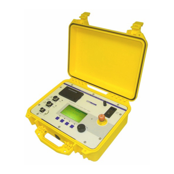
Operation Elements 3.1 Operation Elements 3.2 Front panel Figure 1 : Instrument frontpanel Printer HV cable “H” connection - when the Active lamp is lit, voltage is present on the output LV cable “X” connection - when the Active lamp is lit, voltage may be present on the terminals Tap changer interface connector RS-232 communications port. - Page 14 button locks. Turn it clockwise to release it and allow operation to continue. Power Inlet - Connect only to an earthed power outlet. The unit can be switched on or off using the integrated mains switch. The main fuse holder is also integrated. Grounding Post - used to provide earth continuity to the test object to minimize interference (recommended above transformer ratio 80) Display contrast control *...
-
Page 15: Printer
3.3 Printer The printer on the system is a thermal roll type printer and will only operate with thermal paper. See the specifications for details or the required paper. The supplied paper has a paper low warning indication on it. When the paper is getting towards the end of the roll, there are colored streaks (usually pink or red) on the paper. -
Page 16: Connection And Setup
The following guidelines should be followed. The TTR 2795 has circuitry to minimize the effects of common-mode and high- frequency interference, however good practice in the setting up of the test systems will aid the quality of the measurements made. -
Page 17: Cable Fixing
Ensure, as far as is feasible, that any sources of interference are eliminated from the test area. Equipment such as welding sets and phase-angle furnace controllers should be switched off if at all possible. Keep the “H” and the “X” cables physically separate. This will minimize the effects of any capacitive coupling between them. -
Page 18: Single Phase Transformers
4.5 Single Phase Transformers To connect to a single-phase transformer using the standard three-phase cable set, the cables must be connected to the unit, using the extension leads if required. Ensure that the connectors are locked fully home. The connections should be made as follows: Transformer Terminal TTR Connection... -
Page 19: Current Transformers
If there is no secondary neutral connection the X0 lead (Blue Lead, White plug) should be plugged into the X1 lead (Brown lead, White plug). The connections should be made as follows: Transformer Terminal TTR Connection ANSI, IEEE IEC, VDE “H”... - Page 20 CTs are measured by energizing the secondary and measuring on the primary. For “ring” type current transformers connect the system as follows: Figure 8 : Connecting to a Ring CT For core type current transformers, the “H” connections should be made to the secondary (Low current side) and the “X”...
-
Page 21: Bushing Current Transformers
4.8 Bushing Current Transformers Figure 10 : Connecting to Single Phase BCT It is possible to test bushing current transformers once they are in-situ. This relies on the minimal loading of the test circuit by the secondary measurement system of the TTR instrument. The primary (or secondary depending on the configuration) connections of the transformer should also be jumped out to create a shorted turn and minimize the inductance of the secondary (or primary). - Page 22 Figure 11 : Connecting to three phase BCT Connection and Setup...
-
Page 23: Transformer Look Up Tables
Due to similar reasons the voltage ratio VR and the turns ratio TR is –depending on the winding configuration and phase rotation of the transformer – not always equal. The TTR 2795 therefore internally corrects the entered rated voltages (VR) with the “VR/TR” factor and displays automatically the correct ratio deviation which is calculated out of the rated voltages (boilerplate voltages) as reference and the actually measured (and corrected) ratio value. - Page 24 Note for the transformer configuration look up tables: The “HV Connect” and “LV Connect” give the basic configuration for measuring the transformer to determine the turns ratio (TR). The actual applied configuration depends on the phase rotation of the transformer (see the “Phase Displacement”...
-
Page 25: Tables
4.9.2 Tables The ratio of most transformer configurations can be measured in several ways. Below you can find the tables, which contain the “OLD” style of winding-connections and the “NEW” style of winding- connections. The changes between “New” and “Old” style are made to optimize detection of faults on a specific phase. - Page 26 VECTOR-GROUP TABLE Displ. Phase Winding Winding VR/TR H1-H0 : X1-X2X3 H1-H2H3 : X1-X2 H2-H0 : X2-X1X3 H2-H3H1 : X2-X3 H3-H0 : X3-X1X2 H3-H1H2 : X3-X1 H1-H0 : X2-X1X3 H1-H2H3 : X3-X2 H2-H0 : X3-X1X2 H2-H3H1 : X1-X3 H3-H0 : X1-X2X3 H3-H1H2 : X2-X1 H1-H0 : X3-X1X2 H1-H2H3 : X3-X1...
- Page 27 VECTOR-GROUP TABLE Displ. Phase Winding Winding VR/TR H1-H0 : X1-X2X3 H1-H2H3 : X1-X2 1.154700538 H2-H0 : X2-X1X3 H2-H1H3 : X2-X3 1.154700538 H3-H0 : X3-X1X2 H3-H1H2 : X3-X1 1.154700538 H1-H0 : X2-X1X3 H1-H2H3 : X3-X2 1.154700538 H2-H0 : X3-X1X2 H2-H1H3 : X1-X3 1.154700538 H3-H0 : X1-X2X3 H3-H1H2 : X2-X1...
- Page 28 VECTOR-GROUP TABLE Displ. Phase Winding Winding VR/TR H1-H3 : X1-X3 H1-H2 : X1-X2 H2-H1 : X2-X1 H2-H3 : X2-X3 H3-H2 : X3-X2 H3-H1 : X3-X1 H1-H3 : X2-X1 H1-H2 : X3-X2 H2-H1 : X3-X2 H2-H3 : X1-X3 H3-H2 : X1-X3 H3-H1 : X2-X1 H1-H3 : X3-X2 H1-H2 : X3-X1...
- Page 29 VECTOR-GROUP TABLE Displ. Phase Winding Winding VR/TR H1-H2H3 : X1-X3 H1-H3 : X1-X2X3 0.577350269 H2-H1H3 : X2-X1 H2-H1 : X2-X1X3 0.577350269 H3-H1H2 : X3-X2 H3-H2 : X3-X1X2 0.577350269 H1-H2H3 : X2-X1 H2-H3 : X1-X2X3 0.577350269 H2-H1H3 : X3-X2 H3-H1 : X2-X1X3 0.577350269 H3-H1H2 : X1-X3 H1-H2 : X3-X1X2...
- Page 30 VECTOR-GROUP TABLE Displ. Phase Winding Winding VR/TR H1-H2H3 : X1-X0 H1-H2H3 : X1-X0 0.666666667 H2-H1H3 : X2-X0 H2-H1H3 : X2-X0 0.666666667 H3-H1H2 : X3-X0 H3-H1H2 : X3-X0 0.666666667 H1-H2H3 : X2-X0 H1-H2H3 : X0-X2 0.666666667 H2-H1H3 : X3-X0 H2-H1H3 : X0-X3 0.666666667 H3-H1H2 : X1-X0 H3-H1H2 : X0-X1...
- Page 31 VECTOR-GROUP TABLE Displ. Phase Winding Winding VR/TR H1-H2H3 : X1-X2X3 H1-H2H3 : X1-X2X3 H2-H1H3 : X2-X1X3 H2-H1H3 : X2-X1X3 H3-H1H2 : X3-X1X2 H3-H1H2 : X3-X1X2 H1-H2H3 : X2-X1X3 H1-H2H3 : X1X3-X2 H2-H1H3 : X3-X1X2 H2-H1H3 : X1X2-X3 H3-H1H2 : X1-X2X3 H3-H1H2 : X2X3-X1 H1-H2H3 : X3-X1X2 H1-H2H3 : X3-X1X2...
- Page 32 VECTOR-GROUP TABLE Displ. Phase Winding Winding VR/TR H1-H2H3 : X1-X0 H1-H2H3 : X1-X0 1.154700538 H2-H1H3 : X2-X0 H2-H1H3 : X2-X0 1.154700538 H3-H1H2 : X3-X0 H3-H1H2 : X3-X0 1.154700538 H1-H2H3 : X2-X0 H1-H2H3 : X0-X2 1.154700538 H2-H1H3 : X3-X0 H2-H1H3 : X0-X3 1.154700538 H3-H1H2 : X1-X0 H3-H1H2 : X0-X1...
- Page 33 VECTOR-GROUP TABLE Displ. Phase Winding Winding VR/TR H1-H3 : X1-X2X3 H1-H2H3 : X1-X2 H2-H1 : X2-X1X3 H2-H3H1 : X2-X3 H3-H2 : X3-X1X2 H3-H1H2 : X3-X1 H1-H3 : X2-X1X3 H1-H2H3 : X3-X2 H2-H1 : X3-X1X2 H2-H3H1 : X1-X3 H3-H2 : X1-X2X3 H3-H1H2 : X2-X1 H1-H3 : X3-X1X2 H1-H2H3 : X3-X1...
- Page 34 VECTOR-GROUP TABLE Displ. Phase Winding Winding VR/TR H1-H3 : X1-X2X3 H1-H3 : X1-X2X3 0.866025403 H2-H1 : X2-X1X3 H2-H1 : X2-X3X1 0.866025403 H3-H2 : X3-X1X2 H3-H2 : X3-X1X2 0.866025403 H1-H3 : X2-X1X3 H2-H3 : X1-X2X3 0.866025403 H2-H1 : X3-X1X2 H3-H1 : X2-X3X1 0.866025403 H3-H2 : X1-X2X3 H1-H2 : X3:X1X2...
- Page 35 VECTOR-GROUP TABLE Displ. Phase Winding Winding VR/TR H1-H3 : X1-X2X3 H1-H3 : X1-X2X3 0.866025403 H2-H1 : X2-X1X3 H2-H1 : X2-X3X1 0.866025403 H3-H2 : X3-X1X2 H3-H2 : X3-X1X2 0.866025403 H1-H3 : X2-X1X3 H2-H3 : X1-X2X3 0.866025403 H2-H1 : X3-X1X2 H3-H1 : X2-X3X1 0.866025403 H3-H2 : X1-X2X3 H1-H2 : X3:X1X2...
-
Page 36: Control Knob
Control Knob 5.1 Control Knob The control knob is used once to scroll the selected line item: Rotate the knob to the left and the selector moves down, ..rotate to the right and the selector moves up. To change or edit the selected line item – press (PUSH) the knob..the system then enters an edit screen and allows the value to be edited. - Page 37 By rotating the knob the value can be increased respectively decreased. The cursor jumps to the next edit-field by pressing the knob. Jump one field back by pressing “PREVIOUS”. “DELETE” sets the edit-field back to default (0). List By rotating the knob the entry in the list can be selected. By pressing the knob the selected entry is taken over and the system returns back up to the superior parameter selection list.
-
Page 38: Startup
Startup 6.1 Startup After switching on the system it enters the Startup display: The serial number of this instrument Serial No. The Version of the actual used firmware (system software) FirmWare Version The date of the last factory calibration of the instrument Last Calibration With the soft keys in the bottom line the single sub-menus can be entered: SETUP... -
Page 39: Setting Up Tests
Setting Up Tests 7.1 Setting Up Tests To set-up a new test on the system the set-up menu should be selected from the startup display. Press “UP” until the left most button indicates “SETUP”. Press this button and the system will enter the setup menu. The following screen is shown: Basically the TTR2795 has 3 operating modes;... - Page 40 The LV configuration sets the winding configuration of the LV side of the LV Config transformer. It is not displayed if the HV Configuration is set to “Auto 3 Ph” because the system attempts to determine the LV winding automatically. It is not shown if the HV configuration is set to “CT”...
-
Page 41: Setting Up The Transformer Configuration
The DUT Serial No field allows the user to set a serial number, asset tag number or DUT Serial No. other code to uniquely identify the specific Device Under Test under test. When a set of test results are stored on the unit, they are identified by the DUT Serial No in the memory window. -
Page 42: Setting Test Voltage
If a three-phase transformer is being tested, the best way of performing the measurement is in semi-automatic mode: set the HV Config and LV Config according to the nameplate of the transformer. Set the Ph Displacement to ?? In this mode the TTR will determine the phase displacement (clock-number) of the transformer. It will also double check if the vectorgroup and the phase deviation (clock-number) fit together. - Page 43 If the system is to perform a check on the deviation of the results from the nominal turns ratio, it is necessary to enter values for the “HV Nom Voltage” (the boilerplate voltage for the side connected using the ‘H’ cables) and the “LV Nom Voltage”...
- Page 44 “Nom Tap Number” “Tap Setup” = LV “Step Tap to Tap” = 0.1kV Example 2 A transformer with 16 outputs numbered -7 to +8, each tap gives an adjustment of 5V from a 240V nominal. The primary voltage is 1kV. The nominal tap is tap 0: Primary Secondary Voltage...
-
Page 45: Setting Up A Transformer With Irregularly Spaced Taps
7.5 Setting Up a transformer with irregularly spaced taps If the transformer has irregularly spaced taps, or it has taps on the primary as well as the secondary, it is not possible for the system to calculate the taps for itself and they have to be entered manually. It is still necessary to set the “Total Taps”... -
Page 46: Saving A Setup
The left-hand column shows the description of the data held a specific memory. If this is a Setup (that is, there are no results associated with the entry) the text that is displayed is that held in the “DUT Type” field. If the If the entry in the memory is a set of test results, then the text displayed is the information held in the “DUT Serial No.”... - Page 47 Tap -2 (1 of 5) 3.0 kV 0.90kV Tap -1 (2 of 5) 3.0 kV 0.95kV (3 of 5) 3.0 kV 1.0kV (4 of 5) 3.0 kV 1.05kV (5 of 5) 3.0 kV 1.0kV ******** END OF REPORT ******** Setting Up Tests...
-
Page 48: Running A Test
Running A Test 8.1 Running A Test Before connecting the instrument to the transformer, make sure that the transformer is fully disconnected from both its supply and load and ensure that it is fully de-energized. Ensure that the instrument is correctly connected to the transformer - the ‘X’ cables must be connected to the low voltage side, the ‘H’... -
Page 49: Errors & Warnings While Testing
The user has two menu options available: returns the user to the main menu starts the test procedure running. START 8.2 Errors & Warnings While Testing As soon as the testing process is started, the system check to see if there is still data in the working memory that will be overwritten if the test is run. -
Page 50: Testing Stage 1 - Pretest Stage
transformer - exchange the primary with the secondary connections. If no connection errors are found, there may be short circuit within the transformer itself. A short or overload has been detected on the energization system preventing the Output Voltage Fail required output voltage from being applied to the transformer. -
Page 51: Testing An Untapped Transformer
Press cancel to clear the error box and the system will be ready to start testing again. If the problem persists, go to the OPTIONS menu and turn on the Debug Report. The system will report the measurements made in determining the transformer configuration and where in the process the measurement failed. -
Page 52: Testing A Tapped Transformer Using The Tap Changer Button
When testing large transformers with tap changers, it can be awkward to place the TTR where it can be conveniently operated at the same time as the tap changer system. Tettex supply an optional control button that connects to the system via the Tap Changer socket on the front panel. -
Page 53: Printing The Test Results
If there is insufficient memory to save the results, the instrument reports an error. In this case it will be necessary to go to the memory menu to delete some results or setup and then save the data from there. Saving the results clears them from the main memory so the results displayed on the screen are cleared. -
Page 54: Graphing The Test Results
turns ratio is within the acceptable deviation (Passed), or if no deviation checking is performed. If the ratio is outside the acceptable deviation limit it indicates “F” to show the transformer has failed the test at that point. 8.9 Graphing the Test Results The GRAPH option is only available if a tapped transformer was being tested. -
Page 55: Memory Functions
Memory Functions 9.1 Memory Functions The MEMORY menu allows access to the information stored in the memory on the instrument. Two different types of information are stored in the memory: These memories just hold information on how the test is to be performed on a Setup transformer and what the taps are. -
Page 56: Showing Memory Information On The Screen
******** TTR TEST REPORT ******* Transformer: DUT Serial No. Type: DUT Type Location: DUT Location Tested By: Operator Instrument: TETTEX2795 Serial No.: 1234-56-78 Date Of Test : 09/22/04 Time of Test : 08:23:45 Test Voltage : Auto Max Deviation: 0.5% Configuration: Auto 3ph HV Nom Volt : 3.0 kV... - Page 57 It indicates the date and time the test was performed, whether it is a test or a setup and the number of the memory it is stored in. Beneath that it shows the basic setup information for the stored in the memory Configuration YYn0 Test Voltage...
- Page 58 If there are more taps than can be shown on the screen, rotating the control knob will scroll through the values. Press “OK” to return to the SHOW memory screen. Deleting Memory Information The highlighted memory can be deleted by pressing the “DELETE” button. This displays a message box asking for confirmation.
-
Page 59: Options
10 Options 10.1 Options The general options of the TTR 2795 system can be set by selecting the “OPTION” button from the start-up screen. The following screen is shown:The following screen is shown: 10.2 Editable Options The used system date (dd-mm-yy) can be set. - Page 60 The identification of the instrument (TTR-2795) Instrument ID The serial number of this instrument (also shown in the stat-up screen) Serial No The Version of the actual used firmware (system software) FirmWare Version The date of the last factory calibration of the instrument Last Calibration Next Calib.
-
Page 61: Remotecontrol
(Straight through extension type) to connect to a standard 9 way RS-232 connector on a PC. For other connector configurations, a suitable adaptor should be used. The configuration of the serial port on the TTR 2795 is fixed at 9600 Baud, 8 bits, No parity, 1 Stop Bit. -
Page 62: Remote Control System Error Codes
+ERROR:nnnn:~: Data is encoded into the Fields: using a “big endian”, that is with the highest order bytes transmitted first. The Fields: are encoded as follows: Strings are transmitted with the terminating NULL character removed. The string should be scanned to determine the position of control characters. - Page 63 “maintain” command to indicate connection is to be maintained if it is not transmitting commands. If the host is not going to be transmitting data to the TTR for a period, it should send a “maintain” command every 2 seconds to keep the link active.
-
Page 64: Test Control Functions
The instrument identification field is always returned as “TETTEX2795” irrespective of the instrument options, as these do not affect the operation of the system <Serial No> is the serial number of the instrument. This is passed as a text string. <Version>... - Page 65 determination. The valid voltage levels for the test are: 0x0A (10) - 10 Volts energization 0x28 (40) - 40 Volts energization 0x64 (100) - 100 Volts excitations Returns: +OK:<VectorGroup>:<TestVoltage>:~: - Vector group updated +ERROR:0909:~: - Vector group is invalid +ERROR:090A:~: - Voltage is invalid +ERROR:0902:~: - Working Memory has data +ERROR:0300:~:...
- Page 66 +ERROR:0300:~: - No update - test running Comments: If the tap definition is invalid (more than 40 taps selected or bottom tap out of the range +/-128 or the nominal tap out of range) the system returns an invalid response with the original settings. Also the step percent or step voltage, whichever is applicable is checked for validity.
- Page 67 Test:Info:Location This sets up the location of the UUT Structure: +T:I:L:<Location>:~: Fields: <Location> (string) is a 20 character unit location string. Returns: +OK:~: - The location has been updated. +ERROR:0902:~: - Working Memory has data +ERROR:0300:~: - No update - test running Comments: If a string longer than 20 characters is received it is truncated to 20 characters (plus terminating null).
- Page 68 Test:Measure:Run This runs the measurement procedure. Structure: +T:M:R:~: Fields: None Returns: +OK:~: - Measurement Sequence running +ERROR:090C:~: - Measurement sequence already running +ERROR:090D:~: - Unable to run measurement sequence Comments: The system will report that it is unable to run if the parameters are not set correctly or it has determined there is a fault with the unit.
- Page 69 Comments: If the test system is idle, this will return the results of the last measurement made. Once a test is started, but before any measurements are made, the system will report 0 for <TR>,<I> and <P>. If the test was faulted, the function returns the appropriate fault code. This can be cleared by running another test or by calling the Test:Measure:Halt command while the test system is idle.
- Page 70 <NomTap> (integer) is the index of the nominal tap of the transformer. <StepVal> (float) is the tap-to-tap step value, which is either in Volts or a percentage of the nominal tap voltage, based on the Step Unit set. A negative step value indicates that the tap is on the HV side.
- Page 71 <IB> (float) is the measured energization current for phase B <PB> (float) is the measured phase shift for phase B <TRC> (float) is the measured turns ratio for phase C <IC> (float) is the measured energization current for phase C <PC>...
-
Page 72: Memory Control Functions
<IC> (float) is the measured energization current for phase C, if Leg C was measured, otherwise 0. <PC> (float) is the measured phase shift for phase C, if Leg C was measured, otherwise 0. <Pass> (integer) indicates whether all three phases are within the acceptable percentage deviation from nominal. - Page 73 <StateString> is a 100 character string that returns the state of the memory locations. The first character refers to memory 1, the second to memory 2 and so on. The character indicates the status of the memory: ‘F’ - the memory is currently free ‘S’...
- Page 74 +ERROR:0903:~: - Memory <MemNo> had no data +ERROR:0904:~: - Data transferred but corruption detected +EEROR:0905:~: - <MemNo> is out of range Comments: The data is retained in the memory, and a copy is made in the working memory. Memory:Available This returns the amount of available memory on the system. Structure: +M:A:~: Fields:...
- Page 75 0x01 – Star, no neutral 0x02 – Star, With neutral 0x03 – Zig-zag, no neutral 0x04 – ZigZag, with neutral 0x05 – Single Phase (conventional transformer) 0x06 – Single Phase (current transformer) 0x0E – Use Range Extension transformer The phase displacement is between 0 to 11. <Voltage>...
-
Page 76: System Setup And Calibration
<Deviation> (float) is the maximum acceptable turns ratio deviation. <TimeDate> (DateTime) is the time and date the test was performed. Comments: None Memory:Read:Taps This returns the result for the individual taps from the memory. Structure: +M:R:T:<MemNo>:<TapNum>:~: Fields: <MemNo> (integer) is the memory number to be read. This is in the range of 0 to 100. - Page 77 0x0001 System has printer. If this flag is set the system has a printer available, so should print test reports. Setup:SystemType This sets the system type for the unit Structure: +S:T:<Type>:~: Fields: <Type> (string) is the type of the instrument. This is typically TETTEX2795 or TETTEX2795R Returns: +OK:~: - The System type was set successfully...
- Page 78 Fields: <CalDate> (TimeDate) is the date and time the calibration was performed. <NextCalDate> is the date and time the next calibration is due. Returns: +OK:~: - The dates and times were set successfully +ERROR:0006:~: - Calibration Jumper not inserted +ERROR:0007:~: - Error writing the data +ERROR:0009:~: - One of the parameters was invalid Comments: The system checks the validity of both TimeDate Structure:s before writing them to...
- Page 79 MEAS_SECX256 (0x08) - x256 Secondary Gain MEAS_SECX512 (0x09) - x512 Secondary Gain MEAS_SECX1024 (0x0A) - x1024 Secondary Gain MEAS_SECX2048 (0x0B) - x2048 Secondary Gain MEAS_SECX4096 (0x0C) - x4096 Secondary Gain Returns: +OK:~: - indicates the gain was successfully set. Comments: If an invalid setting was specified, the configuration of the system is indeterminate.
- Page 80 MEAS_EN1V - 0x01 - Energize at 1V MEAS_EN10V - 0x0A - Energize at 10V MEAS_EN40V - 0x28 - Energize at 40V MEAS_EN100V - 0x64 - Energize at 100V MEAS_EN10VCT - 0xFF - Energize at 10V for CT Returns: +OK:~: - The configuration and voltage were set successfully +ERROR:090A:~: - The voltage was invalid +ERROR:0911:~: - The specified configuration was bad Comments:...
- Page 81 Pri. Volts. Range 1, Sec. Volts. Range 2 Pri. Volts. Range 1, Sec. Volts. Range 4 Pri. Volts. Range 1, Sec. Volts. Range 8 Pri. Volts. Range 1, Sec. Volts. Range 16 Pri. Volts. Range 1, Sec. Volts. Range 32 Pri.
- Page 82 Setup:UpdateEEPROM This commits the updated calibration factors to the EEPROM. Structure: +S:U:~: Fields: None Returns: +OK:~: - The dates and times were set successfully +ERROR:0006:~: - Calibration Jumper not inserted +ERROR:0007:~: - Error writing the data Comments: None Setup:ReadProcessedMeters This reads the calibrated meter readings from the system Structure: +S:P:~: Fields:...
- Page 83 Comments If the top bit of the flags register is set (i.e. the standard flag position is set) the flag setting is not updated, but the function returns the current flag register setting. This allows the current configuration of the system to be determined. Remote Control...
- Page 84 Setup:Standard This sets the Standard for the system. Structure: +S:Z:<Standard>:~: Fields: <Standard> (Integer) sets the standard. It is one of the following 0 - Do not change standard, this allows the standard to be queried 1 - Set to ANSI standard. 2 - Set to IEC standard.
-
Page 85: Application Software Apsw 2795
12.1 Application Software APSW 2795 The application software APSW 2795 allows remote operation of the Transformer Turns Ratio Meter TTR 2795. It simplifies the report handling and can be used to integrate the TTR measurements in a complete transformer test system. - Page 86 If a TTR meter is connected the status message TTR 2795 connected will be displayed. Otherwise the message TTR 2795 not connected will appear. When the program is started in the simulation mode the status message TTR 2795 simulated will be shown.
-
Page 87: Structure
Button “Previous Test(s)” This button will load the shortcuts of the three last used files and display them for quick access. 12.3 Structure The interface of the application software consists of four designated areas: - title bar: as common under Windows operating system a title bar is displayed at the top of the window. - tab bar: on the right hand side of the window three tab sheets can be selected which allow access to the main functions of the program (SETUP, MEASURE, ANALYSIS). - Page 88 Status Message If the APSW 2795 is started in simulation mode the message “Simulation” appears in this field. If no TTR 2795 is connected but the program is started in the normal mode the message “TTR 2795 not connected” is shown.
-
Page 89: Tab Sheet Setup
See section “Tab Sheet SETUP” for more details. Tab Sheet Measure This sheet contains alls necessary buttons and displays for remote controlling of the TTR 2795, such as TTR status indication, displaying of applied test, vector group configuration, etc. See section “Tab Sheet MEASURE” for more details. - Page 90 “Notes”. Menu Trafo Data Here the transformer winding system is defined and rated. Although the TTR 2795 detects automatically the vector group and phase displacement if known it will be manually entered in this menu.
- Page 91 The following dialog pops up when clicking “Tap Parameters”: The Tap parameters can be entered here in the same way as in the firmware of the instrument itself. Application Software APSW 2795...
- Page 92 With the field “Activate” it can be selected if a defined tap shall be measured (yes) or not (no). If the tap voltages are evenly distributed they can be calculated automatic: By pressing the button the minimal and maximum tap voltage can be entered and the single tap voltages are evenly calculated and filled in the list. If the tap voltages are not evenly distributed the final values in the list can be edited by the user.
-
Page 93: Menu Options
Menu Conditions This menu offers the possibilities to enter environmental conditions such as temperature, humidity and pressure. Menu Options In this menu you can set some general options Drop-down list “Language” Here you can select the operating language. Please contact our sales department for further support if you could not find your desired language in the list. - Page 94 Drop-down list "Terms according" Currently three different conventions for phase labels are supported. IEC/VDE primary: U, V, W, N secondary: u, v, w, n ANSI/IEEE primary: H0, H1, H2, H3 secondary: X0, X1, X2, X3 AUSTRALIAN primary: A, B, C, N secondary: a, b, c, n Drop-down list "User Interface"...
- Page 95 Menu Auxiliary Here you can enter your own documentation fields. The title and field of each line can be free defined by the user. All titles and text field are also shown in the final printed document. Application Software APSW 2795...
-
Page 96: Tab Sheet Measure
12.5 Tab Sheet MEASURE The tab sheet MEASURE is split into five parts. Display of Measurement Values At the top of the window the actual measurement values are displayed including vector group, test voltage, voltage ratio, ratio deviation and phase deviation. Control of Test Voltage and Tap Changer The editable elements in the middle section are used to specify the test voltage, the tap changer position and - if tertiary winding exists –... - Page 97 Beside the “Progress bar” a status message is displayed which reflects the actual state of the system. Following status messages appear: Status “System Ready” This status message is displayed as long as the system is in idle mode. When this status is active the system is awaiting the start order to begin with the measurements.
-
Page 98: Tab Sheet Analysis
12.6 Tab Sheet ANALYSIS This sheet is intended for making post analysis in a graphical way. New measured data can be compared with older ones for trending purposes or simple threshold levels can be entered to specify PASS/FAIL criteria. Measured values can also be displayed against each other, for example to determine if the voltage ratio is linear with the tap changer position. - Page 99 Button Show Actual Diagram Opens the actual diagram in program, which is associated with the file extension ‘.jpg’, where you can print it. The yellow, green and red area of the graphic can be set by clicking 12.6.1 More Analysis This tool is used to analyze several files at the same time.
- Page 100 the list. Button Remove All Pressing this button will remove all files from the list. Button Save List As Pressing this button will store the actual list in a file. Button Load List Pressing this button will load a list from a file. Button Show Analysis Pressing this button will open a dialog with all files from the list.
- Page 101 Application Software APSW 2795...
-
Page 102: Data Transfer
12.7 Data transfer For transferring data from the TTR 2795 to the computer press button in the key bar at the bottom of the window. A dialog window will pop up where you can choose which measurements shall be uploaded to the computer. - Page 103 In the Tettex TTR 2795, arbitrary phase shift (APS) measurement is achieved by using a single-phase supply and with no extra hardware as elaborated earlier. The necessary three phase equivalent voltages at different transformer terminals are simulated by energising a pair of the transformer terminals and interconnecting certain other terminals using a custom approach.
- Page 104 Once this option is selected a small window pops-up and prompts the user to give-in the activation code. Obtain the activation code from Tettex-Haefely Test AG. Once the correct activation code is given, a message pops up (see image below) confirming that arbitrary phase shift module is activated.
- Page 105 To continue with the arbitrary phase shift measurements, following information should be known. (a) Type of the transformer to be tested. Transformer having at least two three phase windings Transformer having at least one winding in three phase and one winding in single-phase. (b) Primary and secondary winding configuration of the transformer.
- Page 106 The remaining steps to turns ratio and phase shift measurement are as detailed earlier in section 12.5. The resulting display is as follows (for vector group Dd0.75) For the case of a transformer having at least one winding in three-phase and one winding in single-phase, with the primary side winding of the transformer configured as delta, the vector group settings on the primary and secondary should be set-up as shown in the image below.
- Page 107 The remaining steps to turns ratio and phase shift measurement are as detailed earlier in section 12.5. Application Software APSW 2795...
-
Page 108: Accessories
13 Accessories 13.1 Accessories 13.2 Verification Box 2795V The Verification Box is used to check the correct functionality of the Ratio Meter and its connected test cables. Different ratios (1, 10, 100, 1000) can be selected by the selector knob on top. Test cables have to be connected following the description on the front respectively the color code. -
Page 109: Miscellaneous
14.2 Care and Maintenance The TTR 2795 instrument is basically service free, as long as the specified environmental conditions are adhered to. As a result, service and maintenance is restricted to cleaning of the equipment and calibration at intervals stipulated by the application for which the instrument is used. -
Page 110: Packing And Transport
14.6 Customer Support All error messages appear on the display of the TTR 2795 measuring instrument. If persistent problems or faulty operation should occur then please contact the Customer Support Department of HAEFELY TEST AG or your local agent. -
Page 111: Conformity
14.7 Conformity Miscellaneous...
Need help?
Do you have a question about the TTR 2795 and is the answer not in the manual?
Questions and answers