Table of Contents
Advertisement
Quick Links
Advertisement
Table of Contents

Summary of Contents for SWAN Analytical AMI Silica
- Page 1 AMI Silica Version 6.20 and higher A-96.250.671 / 200916...
- Page 2 SWAN representative, or the manufacturer: SWAN ANALYTISCHE INSTRUMENTE AG Studbachstrasse 13 8340 Hinwil Switzerland Internet: www.swan.ch E-mail: support@swan.ch Document Status Monitor AMI Silica Operator’s Manual Title: A-96.250.671 Revision Issue Nov. 2011 First Edition Nov.2013 Main board V2.4, Update to Firmware Release 5.40 Okt.
-
Page 3: Table Of Contents
AMI Silica Table of Contents Safety Instructions ........ - Page 4 AMI Silica Operation ......... . .
- Page 5 AMI Silica 5 Installation .........
-
Page 6: Safety Instructions
AMI Silica Safety Instructions AMI Silica - Operator’s Manual This document describes the main steps for instrument setup, oper- ation and maintenance. Safety Instructions General The instructions included in this section explain the potential risks associated with instrument operation and provide important safety practices designed to minimize these risks. -
Page 7: Warning Notices
AMI Silica Safety Instructions Warning Notices The symbols used for safety-related notices have the following sig- nificance: DANGER Your life or physical wellbeing are in serious danger if such warnings are ignored. Follow the prevention instructions carefully. WARNING Severe injuries or damage to the equipment can occur if such warnings are ignored. - Page 8 AMI Silica Safety Instructions Warning Signs The importance of the warning signs in this manual. Electrical shock hazard Corrosive Harmful to health Flammable Warning general Attention general A-96.250.671 / 200916...
-
Page 9: General Safety Regulations
AMI Silica Safety Instructions General Safety Regulations Legal The user is responsible for proper system operation. All precautions must be followed to ensure safe operation Requirements of the instrument. Spare Parts Use only official SWAN spare parts and disposables. If other parts are used during the normal warranty period, the manufacturer’s... -
Page 10: Restrictions For Use
AMI Silica Safety Instructions Restrictions for use The sample must not contain any particles, which may block the flow cell. Sufficient sample flow is coercive for the correct function of the instrument. WARNING For safe instrument installation and operation you must read... -
Page 11: Product Description
Grab Sample The measuring mode grab sample allows the measurement of samples from remote locations. Second Sam- If required the AMI Silica can be equipped with the optional second sample stream module. ple Stream Sample Se- If measurement of more than two sample streams is required, the... - Page 12 AMI Silica Product Description Alternatively: Open during normal operation, closed on error and loss of power. Closed during normal operation, open on error and loss of power. Summary alarm indication for programmable alarm values and in- strument faults.
- Page 13 AMI Silica Product Description Level Constant head Reagent 2 Overflow tube Reagent 3 Solenoid valve Reagent 4 Sample inlet photometer 6-way valve Sample outlet Peristaltic pump Photometer Loop Magnetic stirrer Flow regulating valve Bubble counter Sample inlet Waste Air Inlet Reagent 1 A-96.250.671 / 200916...
- Page 14 AMI Silica Product Description Measurement The quantities of the reagents are precisely defined by a certain number of rotations of the peristaltic pump. After the predefined cycle quantity of a reagent has been sucked from the container, the 6-way valve is rotated to position 5, where sample from the pho- tometer is sucked into the loop [P].
- Page 15 AMI Silica Product Description 14 6-way valve in position 5: The reagent inlet tube is flushed with sample. The peristaltic pump rotates for a certain time. The reagent free sample in the photometer is sucked into the reagent pipe and then via loop pumped back into the photometer.
-
Page 16: Instrument Specification
AMI Silica Product Description Instrument Specification Power Supply Voltage: 100–240 VAC (± 10%) 50/60 Hz (± 5%) or 24 VDC (± 10%) Power consumption: max. 30 VA Electronics Aluminium with a protection degree of IP 66 / NEMA 4X housing Ambient temperature: -10 to +50 °C... - Page 17 AMI Silica Product Description Dimensions Panel: 400 x 850 x 160 mm Distance between mounting holes: 374 x 824 mm Screw diameter: 8 mm Weight: 16.0 kg 400 mm / 15¾” 13 mm / ½” 374 mm / 14¾” AMI Silica...
-
Page 18: Instrument Overview
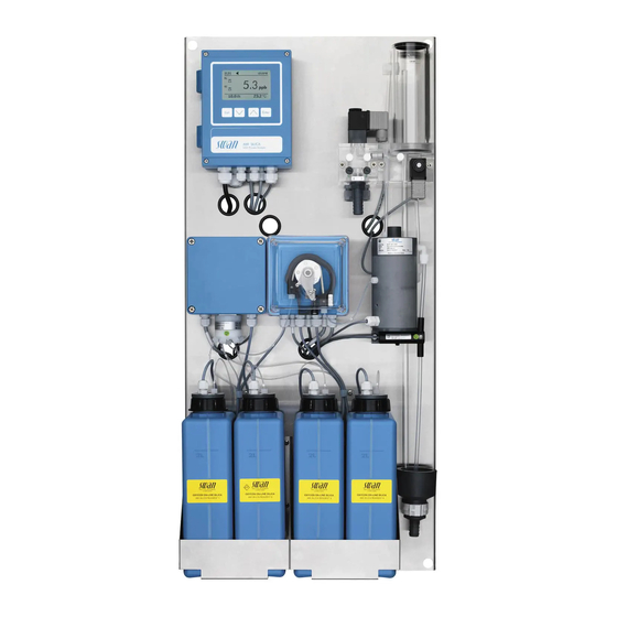
AMI Silica Product Description Instrument Overview Transmitter Flow regulating valve Panel Solenoid valve 6-way valve control box Sample inlet with sample 6-way valve switch (2nd sample stream Peristaltic pump option) Reagent 1 Photometer with magnetic Reagent 2 stirrer Reagent 3... -
Page 19: Installation
AMI Silica Installation Installation Installation Check List Check Instrument’s specification must conform to the National Electri- cal Code, all state and local codes, and all plant codes and stan- dards for electrical equipment. 100 - 240 VAC ( 10%), 50/60 Hz ( 5%) or 24 DC ( 10%), On-site isolated power outlet with ground connection and 30 VA. -
Page 20: Mounting Of Instrument Panel
AMI Silica Installation Mounting of Instrument Panel The first part of this chapter describes the preparing and placing of the system for use. The instrument must only be installed by trained personnel. Mount the instrument in vertical position. -
Page 21: Install The Constant Head
AMI Silica Installation Install the Constant Head Constant head cover Constant head tube Overflow tube O-Ring Flow cell block Flow regulating valve Solenoid valve Level 1 Push the overflow tube [C] through the flow cell block [E] as far as it ends the waste funnel. -
Page 22: Connect Sample And Waste
AMI Silica Installation Connect Sample and Waste 3.4.1 Sample Inlet Use plastic tube (FEP, PA, or PE 4 x 6 mm) to connect the sample line. Mounting of Screw connection SERTO fitting Compression ferrule Knurled nut Flexible tube 3.4.2 Sample Outlet... -
Page 23: Install The 2Nd Sample Stream Option
AMI Silica Installation Install the 2 Sample Stream Option Level Exit Enter AMI SILICA SiO2 Process Analyzer Block housing Sample stream 1 Connecting piece Sample stream 2 2 O-rings Waste (15x20 mm) Blind Plug Fixing screws Flow regulating valve Solenoid valve... - Page 24 AMI Silica Installation 3 Unscrew and remove the flow regulating valve [E] from the flow cell block [F]. 4 Screw the blind plug [D] into the flow cell block. 5 Remove the sample inlet tube [N] from the sample inlet (elbow union) [G].
- Page 25 AMI Silica Installation 1 Remove the plug [A] from the cable gland [B]. 2 Open the transmitter housing. 3 Feed the cable of the solenoid valve through the cable gland [B] into the AMI transmitter housing. 4 Connect the wires to the terminals in the AMI transmitter according to the Connection Diagram, p.
-
Page 26: Install The Ami Sample Sequencer
Sample Sequencer which allows the measurement of up to 6 sam- ple streams, can be connected to the AMI Silica. The installation and the electrical connection of the AMI Sample Sequencer to the AMI Silica is described in the manual of the AMI Sample Sequencer. Firmware After the AMI Sample Sequencer is installed and connected, set the firmware according to your requirements. -
Page 27: Sample Connection With 2Nd Sample Stream
Sample connection with 2 sample stream If a Sample Sequencer is connected to an AMI Silica with a second sample stream option [A], the sample inlet 2 will be automatically switched off and only the sample inlet 1 is active. -
Page 28: Electrical Connections
AMI Silica Installation Electrical Connections WARNING Risk of electrical shock. Do not perform any work on electrical components if the trans- mitter is switched on. Failure to follow safety instructions could result in serious injury or death. Always turn off AC power before manipulating electric parts. - Page 29 AMI Silica Installation WARNING External Voltage. External supplied devices connected to relay 1 or 2 or to the alarm relay can cause electrical shocks Make sure that the devices connected to the following con- tacts are disconnected from the power before resuming in- stallation.
-
Page 30: Connection Diagram
AMI Silica Installation 3.7.1 Connection Diagram CAUTION Use only the terminals shown in this diagram, and only for the mentioned purpose. Use of any other terminals will cause short circuits with possible corresponding consequences to material and personnel. A-96.250.671 / 200916... -
Page 31: Power Supply
Mains cable to comply with standards IEC 60227 or IEC 60245; flammable rating FV1 Mains equipped with an external switch or circuit-breaker – near the instrument – easily accessible to the operator – marked as interrupter for AMI Silica A-96.250.671 / 200916... -
Page 32: Relay Contacts
AMI Silica Installation Relay Contacts 3.8.1 Input NOTICE: Use only potential-free (dry) contacts. The total resistance (sum of cable resistance and resistance of the relay contact) must be less than 50 Ω. Terminals 16/42 If signal output is set to hold, measurement is interrupted if input is active. -
Page 33: Relay 1 And 2
AMI Silica Installation 3.8.3 Relay 1 and 2 NOTICE: Max. load 1 A/250 VAC Relay 1 and 2 can be configured as normally open or as normally closed. Standard for both relays is normally open. To configure a Relay as normally closed, set the jumper in the upper position. - Page 34 AMI Silica Installation CAUTION Risk of damage of the relays in the AMI Transmitter due to heavy inductive load. Heavy inductive or directly controlled loads (solenoid valves, dosing pumps) may destroy the relay contacts. To switch inductive loads > 0.1 A use an AMI relay box avail- able as an option or suitable external power relays.
-
Page 35: Signal Outputs
AMI Silica Installation Signal Outputs 3.9.1 Signal output 1 and 2 (current outputs) NOTICE: Max. burden 510 If signals are sent to two different receivers, use signal isolator (loop isolator). Signal output 1: Terminals 14 (+) and 13 (-) -
Page 36: Signal Output 3
AMI Silica Installation 3.10.1 Signal Output 3 Terminal 38 (+) and 37 (-). Requires the additional board for the third signal output 0/4–20 mA PCB. The third signal output can be operated as current source or current sink (switchable via switch [A]). For detailed information see the corresponding installation instruction. -
Page 37: 3.10.3 Hart Interface
AMI Silica Installation 3.10.3 HART Interface Terminals 38 (+) and 37 (-). The HART interface PCB allows for communication via the HART protocol. For detailed information, consult the HART manual. HART Interface PCB 3.10.4 USB Interface The USB Interface is used to store Logger data and for Firmware upload. -
Page 38: Instrument Setup
AMI Silica Instrument Setup Instrument Setup Activate the Peristaltic pump The occlusion frames of the peristaltic pump are opened during transport and storage. This prevents the pump tubs from sticking together at the pressure points. 1 Turn the occlusion frame [B] clockwise to activate the peristaltic pump. -
Page 39: Establish Sample Flow
AMI Silica Instrument Setup Establish Sample Flow CAUTION Pollution of the reagents If the occlusion frames are not closed, sample may flow into the reagents. Lock the occlusion frames before establishing the sample flow. Overflow tube Flow regulating valve... -
Page 40: Programming
AMI Silica Instrument Setup Programming Programming Program all parameters for external devices (interface, recorders, etc.) Program all parameters for instrument operation (limits, alarms). See Program Overview, p. 69 and for explanations, see Program List and Explanations, p. 74 Configuring Input: NOTICE: use “hold”... -
Page 41: Operation
AMI Silica Operation Operation Function of the Keys Exit Enter to exit a menu or command (rejecting any changes) to move back to the previous menu level to move DOWN in a menu list and to decrease digits to move UP in a menu list and to increase digits... -
Page 42: Measured Values And Symbols On The Display
AMI Silica Operation Measured Values and Symbols on the Display Display when Operating with one Sample Stream 15:20:18 15:10:52 31 B/s 24.2°C A RUN normal operation HOLD input closed or cal delay: Instrument on hold (shows status of signal outputs). - Page 43 AMI Silica Operation Display when Operating with two Sample Streams 15:20:18 15:10:52 15:20:52 ppb ~ 24.2°C 31 B/s A RUN normal operation HOLD input closed or cal delay: Instrument on hold (shows status of signal outputs). input closed: control/limit is interrupted (shows status of signal outputs).
-
Page 44: Software Structure
AMI Silica Operation Software Structure Main Menu Messages Diagnostics Maintenance Operation Installation Menu Messages 1 Messages Reveals pending errors as well as an event history Pending Errors (time and state of events that have occurred at an Maintenance List earlier point of time). -
Page 45: Changing Parameters And Values
AMI Silica Operation Changing Parameters and Values Changing The following example shows how to change the logger interval: parameters 1 Select the parameter you want to Sensors Logger 5.1.2 4.4.1 change. Sensor type FOME Log interval 30 min 2 Press [Enter] Disinf. -
Page 46: Grab Sample Measurement
AMI Silica Operation Grab Sample Measurement Select Menu 4.1 (Operation/Grab Sample) and follow the instruc- tions on the display. Relay status during grab sample measurement: Signal outputs are on hold All limits are switched off 1 Close the flow regulating valve. -
Page 47: Maintenance
AMI Silica Maintenance Maintenance Maintenance Schedule WARNING Stop operation before maintenance. Stop sample flow. Shut off power of the instrument. Weekly Check sample supply for dirt. Check sample flow (see also , p. Monthly Check reagent level Every 6 months Exchange reagent pump tube. -
Page 48: Refill Or Replace Reagents
Reagent container 2 Reagent container 3 Reagent container 4 Holder OXYCON ON-LINE SILCA OXYCON ON-LINE SILCA OXYCON ON-LINE SILCA OXYCON ON-LINE SILCA AMI SILICA REAGENT 1 AMI SILICA REAGENT 2 AMI SILICA REAGENT 3 AMI SILICA REAGENT 4 A-96.250.671 / 200916... - Page 49 AMI Silica Maintenance Reagent The 2 liter reagent canister will last for 1 month of operation with default measurement interval of 10 minutes. The provided reagent consumption set for 3 canister fillings therefore lasts for 3 months of operation. Duration per...
- Page 50 AMI Silica Maintenance Reagent 1 Ammonium molybdate Reagent 1a: Add 56 g of Ammonium molybdate Tetrahydrate Reagent 1b: Add 16 g of Sodium hydroxide pellets WARNING Sulfuric Acid is corrosive and causes severe burns. Read the Material Safety Data Sheets (MSDS) first.
-
Page 51: Verification
AMI Silica Maintenance Verification The “Verification kit for AMI Photometer” is available as an accessory. An optical window with a precisely deter- mined absorbance value is placed into the light beam of the photometer. The actual measured absorbance will be compared to the reference value labeled on each kit. -
Page 52: Calibration
AMI Silica Maintenance Calibration Select Menu 3.1 (Maintenance/Calibration) and follow the instruc- tions on the display. Relay status during calibration: Signal outputs are on hold All limits are switched off 1 Close the flow regulating valve. Calibration 3.1.1 2 Prepare 1 l of Standard. -
Page 53: Cleaning The Flow Cell
AMI Silica Maintenance Cleaning the Flow Cell CAUTION Acrylic glass parts are fragile and scratch-sensitive. Possible damage of acrylic glass parts due to scrubbing materi- als. Never use organic solvents or scrubbing materials to clean acrylic glass parts. Use soft detergent and rinse well. Eliminate lime deposits with a common household deliming agent in standard concentra- tion. - Page 54 AMI Silica Maintenance Constant head cover Constant head tube Overflow tube O-Ring Flow cell block Flow regulating valve Solenoid valve Level Cleaning 1 Remove the constant head cover [A]. 2 Pull the constant head tube [B] (constant head) out of the flow cell block [E].
-
Page 55: Cleaning The Photometer
AMI Silica Maintenance Cleaning the Photometer Clean the photometer after indication by alarm (E020, FOME dirty). Before opening the photometer, switch off the instrument according to instructions in Stop of Operation for Maintenance, p. 45 Material Small brush. Procedure Flow regulating valve... -
Page 56: Cleaning The Solenoid Valve
AMI Silica Maintenance Cleaning the solenoid valve Disassemble The solenoid valve is mounted below the constant head. The sole- noid valve should be disassembled if it does not switch anymore or the solenoid if it is clogged. valve 1 Switch off the instrument according to instructions in Stop of Operation for Maintenance, p. - Page 57 AMI Silica Maintenance NOTICE: The O-rings inside the valve body may stick on the flow cell and fall down if the valve body is removed. 5 Remove the valve body from the flow cell. 6 Remove the white plate (G) with a screw driver size 0 (F).
-
Page 58: Tube Replacement
AMI Silica Maintenance Tube Replacement 6.9.1 Replace the Pump Tubes The pump tube [D] of the peristaltic pump is exposed to a minimal wear. It is therefore recommended to exchange the pump tube every 6 months. CAUTION Pollution of reagents possible. - Page 59 AMI Silica Maintenance Dismount The pump tube can easily be dismounted and mounted. pump tubes Proceed as follows: Pump housing Occlusion frame open Rotor Pump tube Pump inlet Pump outlet 1 Switch off the instrument according to instructions in Stop of Operation for Maintenance, p.
-
Page 60: Tube Numbering
AMI Silica Maintenance 6.9.2 Tube Numbering Level Tube from Reagent container J 6-way valve port 1 Reagent container K 6-way valve port 2 Reagent container L 6-way valve port 3 Reagent container M 6-way valve port 4 6-way valve port 5... -
Page 61: Fill Or Flush Reagent System
AMI Silica Maintenance 6.10 Fill or Flush Reagent System Fill or flush the reagent tubing: after refilling the reagent containers, before a system shut-down to flush the system with demin water until no more reagent is left in the system. -
Page 62: Replacing Fuses
AMI Silica Maintenance 6.12 Replacing Fuses WARNING External Voltage. External supplied devices connected to relay 1 or 2 or to the alarm relay can cause electrical shocks. Make sure that the devices connected to the following con- tacts are disconnected from the power before resuming in- stallation. -
Page 63: Longer Stop Of Operation
AMI Silica Maintenance 6.13 Longer Stop of Operation 1 Proceed according to chapter Stop of Operation for Mainte- nance, p. 2 Empty the measuring cell of the photometer, for example with a pipette and dry it with a soft tissue. -
Page 64: Troubleshooting
AMI Silica Troubleshooting Troubleshooting This chapter provides some hints to make troubleshooting easier. For any detailed information how to handle or clean parts please Maintenance, p. 45. For any detailed information how to pro- gram the instrument please see Program List and Explanations, p. - Page 65 AMI Silica Troubleshooting Check pump A low calibration factor may be caused by leaking tube connec- tions. The delivery volume of the peristaltic pump is approximately delivery 4.2 g/min. volume 2.1 g Flow regulating valve Beaker Peristaltic pump Balance Tube fitting Check the delivery volume of the peristaltic pump as follows: 1 Close the flow regulating valve [A] to stop the sample flow.
-
Page 66: Grab Sample
AMI Silica Troubleshooting 8 After the 6-way valve position has been set, select <Pump> and press [Enter]. 9 Set the pump to <on> for a half minute. The reagent is pumped into the beaker. 10 Read the weight on the display of the balance. -
Page 67: Error List
AMI Silica Troubleshooting 7.3. Error List Error Non-fatal Error. Indicates an alarm if a programmed value is ex- ceeded. Such Errors are marked E0xx (bold and black). Fatal Error (blinking symbol) Control of dosing devices is interrupted. The indicated measured values are possibly incorrect. - Page 68 AMI Silica Troubleshooting Error Description Corrective action E001 – check process Si 1 Alarm high – check programmed value 5.3.1.1.1, p. E002 – check process Si 1 Alarm low – check programmed value 5.3.1.1.25, p. E003 – check process Si 2 Alarm high –...
- Page 69 AMI Silica Troubleshooting Error Description Corrective action – check valve, see Cleaning the solenoid E015 Valve defective valve, p. 54 E017 – check control device or programming in Control Timeout Installation, Relay contact, Relay 1/2 5.3.2 and 5.3.3, p. 87 –...
- Page 70 AMI Silica Troubleshooting Error Description Corrective action – See operating manual Sample E036 Sample Flow 4 low Sequencer (Sample Sequencer) – See operating manual Sample E037 Sample Flow 5 low Sequencer (Sample Sequencer) – See operating manual Sample E038 Sample Flow 6 low...
-
Page 71: Program Overview
AMI Silica Program Overview Program Overview For explanations about each parameter of the menus see Program List and Explanations, p. Menu 1 Messages informs about pending errors and mainte- nance tasks and shows the error history. Password protection possible. No settings can be modified. -
Page 72: Diagnostics (Main Menu 2)
AMI Silica Program Overview Diagnostics (Main Menu 2) Identification Designation AMI Silica * Menu numbers 2.1* Version V6.20-08/16 Peripherals PeriClip 1.06 2.1.3.1* 2.1.3 RoValve 1.60 Factory Test Instrument 2.1.4.1* 2.1.4* Motherboard Operating Time Years / Days / Hours / Minutes / Seconds 2.1.5.1*... -
Page 73: Maintenance (Main Menu 3)
AMI Silica Program Overview Maintenance (Main Menu 3) Calibration Calibration Progress * Menu numbers 3.1* 3.1.5* Service Verification (Progress) 3.2.1.1* 3.2* 3.2.1* Fill System (Progress) 3.2.2.5* 3.2.2* Manual Filling Position 3.2.3.1* 3.2.3 Pump 3.2.3.2* Simulation Alarm Relay 3.3.1* 3.3* Relay 1 3.3.2*... -
Page 74: Operation (Main Menu 4)
AMI Silica Program Overview Operation (Main Menu 4) Grab Sample 4.1* Sensors Filter Time Const. 4.2.1* 4.2* Hold after Cal. 4.2.2* Relay Contacts Alarm Relay Alarm Si 1 (Si 2) Alarm High 4.3.1.1.1* 4.3* 4.3.1* 4.3.1.1* Alarm Low 4.3.1.1.25* Hysteresis 4.3.1.1.35*... - Page 75 AMI Silica Program Overview Scaling Range Low 5.2.4.40.10* 5.2.4.40* Range High 5.2.4.40.20* Relay Contacts Alarm Relay Alarm Si 1(Si 2) Alarm High 5.3.1.1.1* 5.3* 5.3.1* 5.3.1.1* Alarm Low 5.3.1.1.25 Hysteresis 5.3.1.1.35 Delay 5.3.1.1.45 Sample Temp. Alarm High 5.3.1.2.1* 5.3.1.2 Alarm Low 5.3.1.2.25*...
-
Page 76: Program List And Explanations
AMI Silica Program List and Explanations Program List and Explanations 1 Messages 1.1 Pending Errors 1.1.5 Provides the list of active errors with their status (active, acknowledged). If an active error is acknowledged, the alarm relay is active again. Cleared errors are moved to the Message list. - Page 77 AMI Silica Program List and Explanations 2.2.1.5 Ver. History: Review verifications values of the last verifications: Absorbance: Measured absorbance of the reference kit. Reference value: True value of the reference kit according to label. 2.2.2 Miscellaneous: 2.2.2.1 Case Temp: Shows the actual temperature in [°C] inside the transmitter.
-
Page 78: Maintenance
AMI Silica Program List and Explanations 2.4 I/O State Shows actual status of all in- and outputs. 2.4.1 and 2.4.2 Alarm Relay: Active or inactive Relay 1 and 2: Active or inactive Input: Open or closed Signal Output 1 and 2:... - Page 79 AMI Silica Program List and Explanations 3.3 Simulation Select the alarm relay, relay 1 and 2, signal output 1 and 2, input, magnetic valve 1 and 2 or stirrer with the up/down keys. Then press <Enter> to change the setting or value. After confirming the setting with the Enter key, the value is simulated by the relay/signal output.
-
Page 80: Operation
AMI Silica Program List and Explanations 4 Operation 4.1 Grab Sample 4.1.5 Starts a grab sample measurement. Follow the instruction on the screen. See Grab Sample Measurement, p. 44 4.2 Sensors 4.2.1 Filter Time Constant: Used to damp noisy signals. The higher the filter time constant, the slower the system reacts to changes of the measured value. -
Page 81: Installation
2, 4 and 6 are measured, whereas the samples streams 1, 3 and 5 are switched off. Sample streams which are switched off are marked with an “x” behind the measuring value on the AMI Silica display. A-96.250.671 / 200916... - Page 82 Example: If sample stream 1 of the Sample Sequencer is active, the AMI Silica measures the sample stream 1 until the Sample Sequencer changes to the next programmed channel. In the example below, the sample stream 3 (CH3) highlighted in green will be measured as soon as the AMI analyzer has finished the previous measurement.The current...
- Page 83 AMI Silica Program List and Explanations 5.2 Signal Outputs 5.2.1 and 5.2.2 Signal Output 1 and 2: Assign process value, the current loop range and a function to each signal output. NOTICE: The navigation in the menu <Signal Output 1> and <Signal Output 2>...
- Page 84 AMI Silica Program List and Explanations [mA] 0 / 4 1’000 10’000 X Measured value (logarithmic) 5.2.1.40 Scaling: Enter beginning and end point (Range low & high) of the linear or logarithmic scale. In addition, the midpoint for the bilinear scale.
- Page 85 AMI Silica Program List and Explanations As control Signal outputs can be used for driving control units. We distinguish different kinds of controls: output P-controller: The controller action is proportional to the devia- tion from the setpoint. The controller is characterized by the P-Band.
- Page 86 AMI Silica Program List and Explanations Control upwards/downwards Setpoint: User-defined process value (Measured value or flow) P-Band: Range below (upwards control) or above (downwards control) the set-point, within the dosing intensity is reduced from 100% to 0% to reach the set-point without overshooting.
- Page 87 AMI Silica Program List and Explanations 5.2.4.3 Scaling: Define the scaling of the signal output used to transmit a process value. Available functions are: Linear, bilinear or logarithmic for process values. As process values, p. 81 5.3 Relay Contacts 5.3.1...
- Page 88 AMI Silica Program List and Explanations 5.3.1.2 Sample Temp.: Define at which sample temperature an alarm should be issued. 5.3.1.2.1 Alarm High: If the measured value rises above the alarm high value, the alarm relay is activated. Range: 30–70 °C 5.3.1.2.25...
- Page 89 AMI Silica Program List and Explanations 5.3.2 and 5.3.3 Relay 1 and 2: The contacts can be set as normally open or normally closed with a jumper. See Relay 1 and 2, p. 31. The function of relay contacts 1 or 2 are defined by the user.
-
Page 90: Cycle Time
AMI Silica Program List and Explanations 5.3.2.1 Function = Control upwards/downwards: The relays may be used to drive control units such as solenoid valves, membrane dosing pumps or motor valves. When driving a motor valve both relays are needed, relay 1 to open and relay 2 to close the valve. -
Page 91: Run Time
AMI Silica Program List and Explanations 5.3.2.32.1 Actuator = Motor valve Dosing is controlled by the position of a motor driven mixing valve. 5.3.2.32.22 Run time: Time needed to open a completely closed valve Range: 5–300 Sec. 5.3.2.32.32 Neutral zone: Minimal response time in % of the runtime. If the requested dosing output is smaller than the response time, no change will take place. - Page 92 AMI Silica Program List and Explanations 5.3.2.24 daily The relay contact can be activated daily, at any time of a day. 5.3.2.341 Start time: to set the start time proceed as follows: 1 Press [Enter], to set the hours. 2 Set the hour with the [ ] or [ ] keys.
- Page 93 AMI Silica Program List and Explanations 5.3.3.1 Function = End of Batch This function is only available on relay 2. It is used to communicate with canal switching instruments from third-party suppliers. The relay closes for 1 sec. after each valid measurement. If End of Batch is selected, no further selection is possible.
- Page 94 AMI Silica Program List and Explanations 5.3.4.4 Fault: No message is issued in pending error list and the alarm relay does not close when input is active. Message E024 is stored in the message list. Yes: Message E024 is issued and stored in the mes- sage list.
-
Page 95: Set Default
AMI Silica Program List and Explanations 5.4 Miscellaneous 5.4.1 Language: Set the desired language. Language German English French Spanish 5.4.2 Set defaults: Reset the instrument to factory default values in three different ways: Set defaults Calibration In parts Completely Calibration: Sets calibration values back to default. All other values are kept in memory. - Page 96 AMI Silica Program List and Explanations 5.5 Interface Select one of the following communication protocols. Depending on your selection, different parameters must be defined. 5.5.1 Protocol: Profibus 5.5.20 Device address: Range: 0–126 5.5.30 ID-Nr.: Range: Analyzer; Manufacturer; Multivariable 5.5.40 Local operation: Range: Enabled, Disabled 5.5.1...
-
Page 97: Material Safety Data Sheets
10.1. Reagents Catalogue No.: Part of Article No. A - 85.420. 560 Product name: OXYCON ON-LINE SILICA Reagent 1a for AMI Silica Ammonium heptamolybdate tetrahydrate Catalogue No.: Part of Article No. A - 85.420. 560 Product name: OXYCON ON-LINE SILICA... -
Page 98: Default Values
AMI Silica Default Values Default Values Operation: Sensors: Filter Time Const.:..............10 Sec Hold after Cal.:..............300 Sec Alarm Relay ..............same as in Installation Relay 1 and 2 ..............same as in Installation Input ..............same as in Installation Logger Logger Interval:............Event Driven Clear Logger: ................no... - Page 99 AMI Silica Default Values Setpoint: ................1.0 ppm Hysteresis:................10 ppb Delay: ..................30 Sec If Function = Control upw. or dnw: Parameter:.................. Si 1 Settings: Actuator: ............Frequency Settings: Pulse Frequency: ..........120/min. Settings: Control Parameters: Setpoint:......1.00 ppm Settings: Control Parameters: P-band: ......10 ppb Settings: Control Parameters: Reset time:......
-
Page 100: Index
AMI Silica Index Index Interface ....HART Alarm Relay ..Interface Modbus Ammonium Ferrous Sulfate .. - Page 101 AMI Silica Index ..Reagent 2 Signal Outputs ... . . Sulfuric Acid Signal Sequencer ..Reagent 3 Silica Measurement ..
-
Page 102: Notes
AMI Silica Notes Notes A-96.250.671 / 200916... - Page 103 AMI Silica Notes A-96.250.671 / 200916...
- Page 104 AMI Silica SWAN is represented worldwide by subsidiary companies and distributors. cooperates with independent representatives all over the world. SWAN Products Analytical Instruments for: High Purity Water Feedwater, Steam and Condensate Potable Water Pool and Sanitary Water Cooling Water Waste Water and Effluents Made in Switzerland A-96.250.671 / 200916...
Need help?
Do you have a question about the AMI Silica and is the answer not in the manual?
Questions and answers