Advertisement
Table of Contents
- 1 Table of Contents
- 2 Safety Recommendations
- 3 Meet Your Torq-Tronics
- 4 Chapter 1 - Features
- 5 Chapter 2 - Installation
- 6 Chapter 3 - Testing Torque Wrenches and Torque Screwdrivers
- 7 Chapter 4 - Power Tool Testing Overview
- 8 Chapter 5 - Joint Simulators and Power Tool Testing
- 9 Chapter 6 - Filters
- 10 Chapter 7 - Testing Power Tools under 10 Inch-Pound Capacity
- 11 Chapter 8 - Testing Non-Shutoff Pulse Tools
- 12 Chapter 9 - Testing Power Tools of over 10 Inch-Pound Capacity
- 13 Chapter 10 - Calibration
- 14 Chapter 11 - Frequently Asked Questions
- 15 Specifications
- Download this manual
Torq-Tronics
®
Digital Torque
Tester
Owners Manual
Version 2.1A
5/2001
P/N: 857432
For Models: 10I (10191), 50I (10192), 100I (10193), 300I (10194), 80 (10195,
150 (10196), 150 (10197), 250 (10197), 600 (10198)
Sturtevant RIchmont
Division of Ryeson Corporation
3203 N. Wolf Road
Franklin Park, IL 60131
Phones: 800/877-1347 847/455-8677
Fax: 847/455-0347
E-mail: CustomerService@srtorque.com
Web: www.srtorque.com
An ISO 9001 Company
Advertisement
Table of Contents

Subscribe to Our Youtube Channel
Summary of Contents for Sturtevant Richmont Torq-Tronics 10I
- Page 1 5/2001 P/N: 857432 For Models: 10I (10191), 50I (10192), 100I (10193), 300I (10194), 80 (10195, 150 (10196), 150 (10197), 250 (10197), 600 (10198) Sturtevant RIchmont Division of Ryeson Corporation 3203 N. Wolf Road Franklin Park, IL 60131 Phones: 800/877-1347 847/455-8677 Fax: 847/455-0347 E-mail: CustomerService@srtorque.com...
-
Page 3: Table Of Contents
Table of Contents Section Page Safety Recommendations ..........2 Meet Your Torq-Tronics®... -
Page 4: Safety Recommendations
Safety Recommendations For your safety and the safety of others, read and understand the safety recommendations before installing or operating the Torq-TronicsÒ. Torq-Tronics® Digital Torque Testers are designed and constructed to provide the user with a safe and reliable means of calibrating torque wrenches and power tools. Should a fault occur which impairs its function and/or compromises its safe use, immediately dis- connect the unit from its power source and secure against unitended operation. - Page 5 Torq-Tronics® Digital Torque Testers should be mounted and located such that inadver- tent movement will not allow the unit to be dislodged, possibly causing personal injury or damage to the unit. Should the unit be dropped, it should be checked by someone qualified in the service of electronic instrumentation.
-
Page 7: Meet Your Torq-Tronics
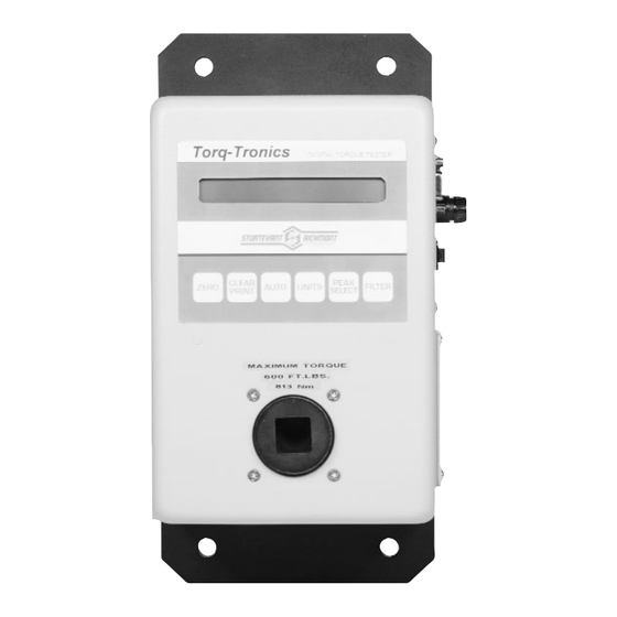
Meet Your Torq-Tronics® Back Plate Mounting Hole (4 locations) Backlit LCD Display Keys Zero Key Clear/Print Key Auto Key Units Key Peak Select Key Filter Key Transducer Battery Compartment Cover Power Switch Fuse Serial Port Charger Receptacle... - Page 8 This page intentionally left blank.
-
Page 9: Chapter 1 - Features
Chapter 1 - Features Back Plate The Back Plate of your Torq-Tronics® unit provides primary structural strength for it and a means by which the unit may be installed. Mounting Holes The Mounting Holes in the Back Plate provide a means of securing the unit in its' installed location. - Page 10 Peak Select Key The Peak Select key is used to select from among the three modes of operation: Track, Peak, and Initial Peak. When turned on, your Torq-Tronics® always boots into Track mode. Each time this key is pressed, it pages to the next mode of operation. Track mode is used for calibration of the Torq-Tronics®...
- Page 11 Serial Port The serial port is a 9-pin port for serial communications with either a computer or serial printer. Data is sent to the port for transmission when the display is cleared, whether auto- matically or manually. Charger Receptacle The charger receptacle is provided for connection of the charger to the tester.
- Page 12 This page intentionally left blank.
- Page 13 Chapter 2 - Installing Your Torq-Tronics® Mounting To Wall or Bench - Location Selection There are several items that must be considered when selecting the location where your Torq-Tronics® will be mounted. These are: Tool proximity. Do you want to test tools at or near their use location or do you want to bring the tools to a central location? Will you be using a computer and Torque Tool Manager (TTM) software with your Torq-Tronics®? Solidity of mount.
- Page 14 Mounting to Selected Support Once the installation location has been determined, the actual installation process can begin. 1. Place your Torq-Tronics® in the selected mounting location, supported as necessary to assure stability of the location and safety. 2. Mark the location of the mounting holes on the surface to which the tester is to be mounted.
-
Page 15: Chapter 2 - Installation
Activate terminal software. ii. Move the power switch on the Torq-Tronics® to the on position. iii. The message "Sturtevant Richmont" then "System 7 Ver 1.1" then "TORQTRONICS [Model]" will appear in the terminal software window if the Torq-Tronics is properly connected and the proper serial port is selected and properly configured. - Page 16 Move the power switch on the Torq-Tronics® unit to the on position. ii. Turn on the printer. iii. The message "Sturtevant Richmont" then "System 7 Ver 1.1" then "TORQTRONICS [Model]" will print if the printer is properly connected and the power is on.
-
Page 17: Chapter 3 - Testing Torque Wrenches And Torque Screwdrivers
± 1% I.V. Tools of accuracy tighter than ± 4% I.V. should be tested on a torque tester of tighter accuracy. This includes most dial- and beam-type torque wrenches. If you have a need to calibrate such tools, contact Sturtevant Richmont for assistance in selecting an appropriate torque measurement system. - Page 18 Preparing the Torque Wrench Check that the torque wrench to be tested is of equal or lesser torque capacity than the tester. Under no circumstances should the Torq-Tronics® be used beyond its' rated capaci- ty! Adjust the torque wrench to the desired torque level for testing. If your Torq-Tronics®...
-
Page 19: Chapter 4 - Power Tool Testing Overview
Chapter 4 - Power Tool Testing Overview Types of Power Tools Power tool types may be broken down by basic categories: the means by which they are powered, the means by which they apply torque, and the means by which torque application stops. - Page 20 than tester), the offset can be used to avoid having to build an exact model of the joint (using the joint simulator and filter) to obtain identical results. As long as the actual joint remains the same (no new components or design changes to existing components) and the test results are in the 50 - 56 inch-pound range, the tool is producing good assemblies.
- Page 21 where both techniques (correlative and tool-specific) are employed, the possibility of confu- sion exists. This also adds to the cost of training new calibration personnel, as well as increasing the probability of error. The record keeping requirements for the tool-specific approach are slightly larger than those for the correlative approach.
- Page 22 The tool and joint do not stop interacting the instant the tool shuts off. All of the rotating components in the tool have momentum from the rotation. Once the power shuts off, these components (motor shaft, drivetrain components, chuck, and bit or socket) continue to inter- act with the fastener until all momentum is dissipated.
-
Page 23: Chapter 5 - Joint Simulators And Power Tool Testing
Chapter 5 - Joint Simulators and Power Tool Testing Joint Hardness Joint hardness is the rate at which a joint develops clamping force as torque is applied to the fastener. Any given joint may be "hard", "soft", or somewhere in between. Note: Joint hardness is classified in accordance with the ISO 5393 standard. - Page 24 The third diagram is of a soft joint. Notice the slow rise in torque; it takes more time - and fastener rota- tion - to reach the same installation torque. The angle of fastener rotation is greater than 270º. TIME/ANGLE Joint Hardness and Power Tool Calibration Almost all non-impacting power tools rely on the reaction of the joint to determine when to shut off.
- Page 25 The joint simulator may or may not contain additional elements such as multi-part housings. Below are photographs of a Sturtevant Richmont joint simulator using Belleville washers. The joint simulators of 80 foot-pound capacity and above are the same, except that a spring is substituted for the washer and no adjustment of the joint rate is made.
- Page 26 In these two photographs, two more washer configura- tions are displayed, each as stacked on the bolt. The photograph on the left depicts a stack that will emulate a joint slightly harder than the stack in the photo to the right.
- Page 27 This photograph shows the rear of the joint simulator, with the base to the front. Two #8-32 setscrews are located in the small neck diameter of the base. To install the joint simulator, use a hex key to back the setscrews out of the female hex.
- Page 28 Joint Simulator Washer Configuration Procedure This procedure is used to obtain a washer stackup that will emulate the actual joint to be tightened by the power tool. The goal is that the same number of degrees of rotation be obtained on the joint simulator as was measured in the prior procedure for the same torque values.
-
Page 29: Chapter 6 - Filters
Chapter 6 - Filters Purpose The electronic filters in the Torq-Tronics® Digital Torque Testers perform two key func- tions: preventing electronic noise from causing inaccurate torque readings, and assisting in the discrimination of the true applied torque signal from the extraneous signals generated by power tool mechanisms. - Page 30 The tool actually shut off at the peak labeled point #2. Once the power driving the bit was shut off, regardless of the means, the bit rebounded off the drive of the fastener, and created a backlash through the drive mechanism of the tool. This created torque in the opposite direction, as displayed by the line running from point #2 to point #3.
-
Page 31: Chapter 7 - Testing Power Tools Under 10 Inch-Pound Capacity
Chapter 7 - Testing Power Tools of Under 10 Inch- Pound Capacity Power tools of less than 10 Inch-Pound capacity should be tested without the use of a joint simulator. This includes clutch, stall, bypass, and pulse-type power tools. Tools of this capacity range are the only tools which should be tested without a joint simulator. - Page 32 * Slowly and carefully apply steadily increasing force to the torque wrench until the fas- tener starts to move. It is important the torque applied be just enough to barely move the fastener. If the fastener is rotated more than just a few degrees, the torque measure- ment will be higher than the applied torque by a significant percentage.
- Page 33 Preparing the Torq-Tronics® for Testing 1) Use the power switch to turn on the tester. 2) Allow the tester to boot up. 3) After the capacity and software messages have been displayed and cleared, the tester will display it's operating status on the LCD. This will consist of: a) A plus (+) or minus (-) sign in front of b) a torque value at or near zero, followed by c) the units of measure currently in use.
- Page 34 This page intentionally left blank.
-
Page 35: Chapter 8 - Testing Non-Shutoff Pulse Tools
Chapter 8 - Testing Non-Shutoff Pulse Tools Testing non-shutoff pulse tools requires use of the filters on the Torq-Tronics® testers, but may or may not require use of the joint simulator. Some pulse tools may be tested by engaging the drive of the Torq-Tronics® transducer directly. The only means of determin- ing whether or not any specific tool requires use of the joint simulator is experimentation. - Page 36 6) If you want the test results cleared from the LCD after a few seconds, Press the Auto key once. Activating the Auto function will also send the data to the computer or print- er if you are using one. If you wish to hold the test results until you clear them, simply do not press the Auto key.
-
Page 37: Chapter 9 - Testing Power Tools Of Over 10 Inch-Pound Capacity
Chapter 9 - Testing Power Tools Over 10 Inch-Pound Capacity This chapter covers testing power tools of over 10 inch-pound capacity. Tools in this range require the use of a joint simulator as well as the filters on the Torq-Tronics®. This proce- dure assumes the tester has been installed per the instructions in Chapter 2 of this manual. - Page 38 8) Compare the results to the actual applied torque obtained from the joint. a) If the results agree with the actual output of the tool on the joint, record the information on the joint simulator washer configuration and filter used for this test for future use with this tool.
- Page 39 FLOWCHART 1 Measure Joint - Fastener Rotation - Installation Torque Configure Simulator - Same rotation as joint. Install Simulator Modify Simulator Remove Simulator Start Torq-Tronics - Power - Units - Mode - Filter Change Filter Test Tool - 3 rundowns Filters Tested Compare Results...
- Page 40 This page intentionally left blank.
-
Page 41: Chapter 10 - Calibration
Chapter 10 - Calibration The calibration procedure for each model differs primarily in the arm and weight combina- tion required to reach the calibration points for the model's torque capacity. Each procedure requires the use of: * A computer equipped with a serial port and terminal software. * A serial cable. - Page 42 13) Again hang the weight platform (hook) and the full-scale weights (100%) (found in the "Calibration Table - Torq-Tronics® Models") on the calibration arm - gently, and imparting as little motion to the weights as possible. Wait for the arm to completely stop moving, then enter :CM0 into the terminal software and press the Enter key.
- Page 43 5) Hang weight platform and 10% weights on the calibration arm, gently. Wait until the arm has completely stopped moving. 6) The torque displayed on the LCD's should be within the accuracy tolerance for the 10% calibration point for the unit. 7) Repeat steps 5 and 6 with the 20%, 50%, 80%, and 100% loads as specified in the "Calibration Table - Torq-Tronics®...
- Page 46 This page intentionally left blank.
-
Page 47: Chapter 11 - Frequently Asked Questions
What is Torque Tool Manager? Torque Tool Manager is software designed by Sturtevant Richmont to enable owners of our various digital torque testers to immediately and economically create a torque calibration system meeting all ISO and QS-9000 requirements. This software runs on any PC running Windows 3.1 or later, and with the addition of a serial cable:... - Page 48 Why do joint simulators 80 ft.-lbs. capacity and higher have springs instead of washers? When the joint simulator is used with power tools, the washers wind up rotating around the bolt as well as being compressed by it. This generates a considerable amount of heat. In the washer sizes necessary for use in larger joint simulators, the heat generated by this fric- tion during rundown is so high that in one or two rundowns the simulator is too hot for safe use.
-
Page 49: Specifications
Specifications The specifications contained herein are applicable solely to the models listed on the front cover and having Version 1.1 software. Software version is displayed on unit startup. Specifications subject to change without notice. General Characteristic Specification Accuracy +/- 1% Indicated Value Accuracy Range 10% - 100% Capacity Accuracy Direction... - Page 50 Units of Measure Model Units of Measure Model 10I In-Oz, In-lb, cNm, dNm, Nm Model 50I In-Oz, In-lb, dNm, Nm Model 100I In-lb, Ft-lb, dNm, Nm Model 300I In-lb, Ft-lb, Nm Model 80 In-lb, Ft-lb, Nm Model 150 In-lb, Ft-lb, Nm Model 250 In-lb, Ft-lb, Nm Model 600...
Need help?
Do you have a question about the Torq-Tronics 10I and is the answer not in the manual?
Questions and answers