Table of Contents
Advertisement
Quick Links
SOYAL
ACCESS CONTROL SYSTEM
Contents
1
Product
or
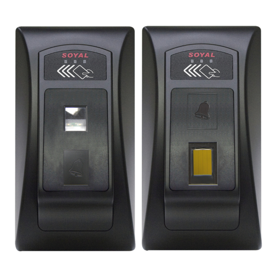
AR-881EV
AR-881EF
Installation
4
2
3
5
External WG keyboard
※ If you want to program system on controller directly, please order WG keyboard then install it according to the following pattern.
1
Connector Table
P4
P6
P5
P7
Cable:
P1
Wire Application Wire
Color
1
Blue White (N.O.)DC24V1Amp
Lock Relay
2
Purple White (N.C.)DC24V1Amp
3
White
Common-COM-Point
Door Contact
4
Orange
Exit Switch
5
Purple
Alarm Relay
6
Gray
7
Thick Red DC 12V
Power
8
Thick Black DC 0V
Cable:
P2
Wire Application Wire
Color
Beeper
1
Pink
2
Yellow
LED
3
Brown
Door Output
4
Blue White
5
Thin Green Wiegand DAT: 0 Input
Wiegand
6
Thin Blue Wiegand DAT: 1 Input
WG Door Contact
7
Orange
WG Exit Switch
8
Purple
®
AR-881EF/AR-881EV
2
User Guide
3
Pull the cables from the square hole of the mounting plate.
Use a screwdriver to screw the base onto the wall.
Connect the terminal cables to the body and attach the body to the mounting plate.
1
Assemble the covers with the Allen key and screws (accessories supplied).
Turn on the power and LED will light and beep will sound.
2
3
P3
P2
P1
Description
(COM)DC24V1Amp
Negative Trigger Input
Negative Trigger Input
Transistor Output Max. 12V/100mA
(Open Collector Active Low)
Description
Beeper Output 5V/100mA, Low
Red LED Output 5V/20mA, Max
Green LED Output 5V/20mA, Max
Transistor Output Max. 12V/100mA
(Open Collector Active Low)
Negative Trigger Input
Negative Trigger Input
Terminal Cables
P1
P2
P4
P5
P6
※
P7
P7
only provide to the controller that have doorbell function.
※
Remove the Protection plug that in the bottom left.
(※ Do not lose protection plug or it will affect the protection level.)
WG Keyboard cable will be connected to the pin board.
WG Keyboard connected to the controller from the bottom left of the hole.
When you finish programming system, please put protection plug back to the
controller.
Cable:
P3
Wire Application Wire
TCP/IP Output
Cable:
P4
Wire Application Wire
RS-485 for Lift
Controller
Cable:
P5
Wire Application Wire
Anti-Tamper
Switch
Cable:
P6
Wire Application Wire
Power
Security trigger signal
Arming
Duress
Cable:
P7
(For the controller that doorbell function.)
Wire Application Wire
Doorbell
4
Tools
Flat Head Cap Philips
Tapping Screw: 4x38
P3
Flat Head Hex Socket
Screw: M3x8
Security Torx Wrenches
Protection Plug
Color
Description
1
---
---
2
---
---
3
Orange White Net - RX-
4
Orange
Net - RX+
5
Green White Net - TX-
6
Gerrn
Net - TX+
7
---
---
Color
Description
1
Thick Green RS-485(B-)
2
Thick Blue RS-485(A+)
Color
Description
1
Red
N.C.
2
Orange
COM
3
Yellow
N.O.
Color
Description
1
Red
DC 12V Output
2
Purple
Security trigger signal Output
3
Red White Arming Output
4
Yellow White Duress Output
Color
Description
Transistor Output Max. 12V/100mA
1
Black White
(Open Collector Active Low)
2
Black
GND
V110221
Advertisement
Table of Contents

Related Manuals for Soyal AR-881EF


Summary of Contents for Soyal AR-881EF
- Page 1 SOYAL ® AR-881EF/AR-881EV V110221 ACCESS CONTROL SYSTEM Contents Product User Guide Terminal Cables Tools Flat Head Cap Philips Tapping Screw: 4x38 Flat Head Hex Socket Screw: M3x8 Security Torx Wrenches ※ AR-881EV AR-881EF Protection Plug only provide to the controller that have doorbell function.
- Page 2 Biometrics Device Access controller Fingerprint & Finger Vein V110221 Notice 1.Tubing: The communication wires and power line should NOT be bound in the same conduit or tubing. 2.Wire selection: Use AWG 22-24 Shielded Twist Pair to avoid star wiring. 3.Power supply: Don’t equip controller and lock with the same power supply.
- Page 3 (NN=00~15); HHMMhhmm=Starting time to ending time; 6543217H= 7 days of week + Holiday (F= 0: disable; 1: enable)] [e.g.] AR-881EF/EV (without WG reader), to set second time zone which could be passed only at 9:30am to 4:20pm on Mon, Wed and Fri.
- Page 4 3. Extra WG keypad panel is needed for adding card or downloading data connected to PC. 4. Each finger need to be collected 3 times enrolling for AR-881EV / Each finger need to be collected 1 times enrolling for AR-881EF.
- Page 5 Reset all user card data: Access programming mode → 29 Firmware Upgrade Get the upgrade software from SOYAL or our distributor and run “UdpUpdater” software Execute the software The software is within SOYAL CD or Login the SOYAL web to downloads Update the firmware [Please login the SOYAL web to download the new ISP Firmware.]...
- Page 6 Fingerprint & Finger Vein V110221 IP Setting Open your Web Browser and input factory default IP address: http://192.168.1.127 If the IP address of AR-881EF/EV has changed We must enter the new IP address. Page menu Monitor the on-line computer IP Setting...
- Page 7 Default value:1234 ;disable PIN=0000) Enabling or Disabling into arming status Card+NNNN NNNN:Arming PWD Enabling or Disabling each device into arming status. Card+NNNN U=Enable target unit (0=AR-881EF/EV , 1=WG Reader) Enabling all device into arming status. Card+NNNN Disabling all device into arming status. Card+NNNN TTT=Door open waiting time: 001~600=1~600 sec.;...
- Page 8 1: Access 064 Networking Anti-pass-back ※0: Disable 1: Enable 128 Networking [e.g.] DDD value of AR-881EF to Enable "Auto Open" + "Exit by Push Button" + "Anti-pass-back" =004+016+128= 148 As a result of that, the command will be 20 ※Default Value Function Option...
Need help?
Do you have a question about the AR-881EF and is the answer not in the manual?
Questions and answers