
Summary of Contents for VR Avionics Walter M601
- Page 1 TSLM Walter M601 Engines & PERATIONAL NSTALL ANUAL Updated: 29 June 2016 Copyright 2016 by VR Avionics...
- Page 2 VR Avionics, Inc. VR Avionics hereby grants permission to download a single copy of this manual and of any revision to this manual onto a hard drive or other electronic storage medium to be viewed for...
-
Page 3: Table Of Contents
Upper ITT Exceeds........................26 Lower ITT Exceeds........................26 N1 Exceeds ..........................26 N2 Exceeds ..........................26 Torque Exceeds ........................27 Max. Unit Temperature ºC .......................27 Min. Unit Temperature ºC ......................27 Last Attempted Start Time (seconds) ..................27 06/29/16 © 2016 VR Avionics page 3 of 33... - Page 4 System Requirements........................30 SetView download and Installation....................30 Using SetView..........................30 Viewing and recording parameters...................31 Synchronizing with the system....................31 Sharing files via email.......................31 Adjusting the configuration.......................32 Opening and viewing history files.....................33 Diagnostic test and troubleshooting..................33 06/29/16 © 2016 VR Avionics page 4 of 33...
-
Page 5: Introduction
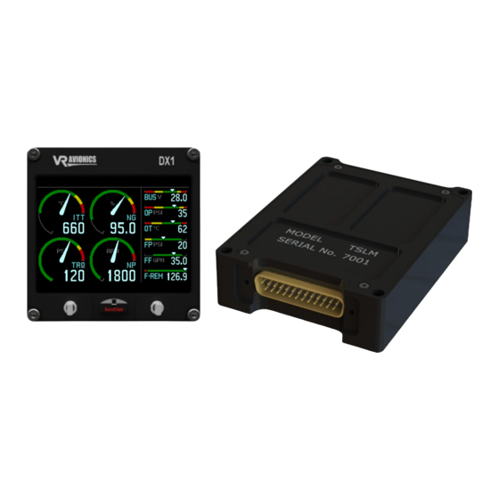
This manual describes the installation and operation of the Turbine Start Limit & Monitor (TSLM) from VR Avionics when used with a Walter/GE M601 engine. The TSLM is a unit (black box) which can function standalone or with other units (black boxes) from VR Avionics as shown below. This manual is dedicated to the TSLM, so when planning to install further units the user must also include the manuals of these other units. -
Page 6: Operation
The pre-start checks can be bypassed by double-clicking the START button. The “double-click start override” setting must be enabled in the TSLM configuration for this to work. 06/29/16 © 2016 VR Avionics page 6 of 33... -
Page 7: Initiating A Run
While conducting the run the TSLM did not detect any signal from the N1 sensors. A signal should have been detected. Check wiring. If you get the above warning, check your wiring to rectify this. See also Determining Engine State. 06/29/16 © 2016 VR Avionics page 7 of 33... -
Page 8: Automatic Protection Limiting
In this alternative (where N1 will read zero) both the ITT and N2 parameters need to be above 400 (400 °C ITT and 400 rpm N2) for the engine state to be considered as running. 06/29/16 © 2016 VR Avionics page 8 of 33... -
Page 9: Parameter Exceeds
1 second. The TSLM light will then stop blinking, which will indicate that the TSLM is now ready to accept new commands from the pilot (start, run, etc.). 06/29/16 © 2016 VR Avionics page 9 of 33... -
Page 10: Operational Check Lists And Codes
EHT error – Limiting circuit disabled or faulty. N1 error – No N1 signal detected during RUN ISOL error – Start attempted in ISOL without double-click (pre-start checks override) Memory error – History log more than 90% full 06/29/16 © 2016 VR Avionics page 10 of 33... -
Page 11: Electrical & Mechanical Specifications
50 mA Operating Temperature -40°C to +85°C Storage Temperature -55°C to +125°C Dimensions (SN 7001 and later) Weight 180g (0.4 lb) Dimensions 100 x 75 x 25mm (3.94" x 2.95" x 0.98") 06/29/16 © 2016 VR Avionics page 11 of 33... -
Page 12: Dimensions (Sn 5001 - 6200)
3 – TXD 5 – GND The TSLM will transmit a stream of data 10 times per second out on pin 2. Please contact VR Avionics should you require detailed protocol information. 06/29/16 © 2016 VR Avionics page 12 of 33... -
Page 13: Installation
✔ Description Part Numbers Crimp contacts M24308/10-1 M39029/63-368 AMP 205090-1 Crimp tool M22520/2-01 AFM8 (DMC) Crimp tool positioner M22520/2-08 K13-1 (DMC) Insertion tool MS1969/1-02 DAK 145 Extraction tool MS1969/1-02 DAK 145 06/29/16 © 2016 VR Avionics page 13 of 33... -
Page 14: Electrical Installation
A short circuit between any of the wires may cause damage to the TSLM and/or other equipment. VR Avionics does not supply connectors or wire for wiring up your TSLM. We recommend that standard aircraft grade wiring and connectors be used during installation. 20 gauge wire is sufficient for most lines to the unit. -
Page 15: Power And Ground
12 and 24 of the TSLM module. The ground wire will not be carrying large current, which means a single 20 AWG wire to pin 13 will be sufficient. Figure 1 - Power and Ground Wiring 06/29/16 © 2016 VR Avionics page 15 of 33... -
Page 16: Ignition Circuit
When using two separate exciter (igniter) boxes, each one only capable of driving one spark-plug, the ignition circuit in the following figure may be used instead… Figure 3 - Dual Exciters Ignition Circuit Wiring 06/29/16 © 2016 VR Avionics page 16 of 33... -
Page 17: Start/Run Selection
TSLM to the start contactor. The thick cable from the start contactor runs to terminal C on the starter/generator. Figure 5 – Start Contactor Wiring 06/29/16 © 2016 VR Avionics page 17 of 33... -
Page 18: Start Interrupter Valve
‘Alternative Interrupter Activation’. If you choose the alternative circuit, this configuration property needs to be set to 1 instead of 0 as explained in the Alternative Interrupter Activation setting. 06/29/16 © 2016 VR Avionics page 18 of 33... -
Page 19: Limiting (Eht) Circuit
Figure 8 – EHT wiring with Limiter Enable Switch Alternatively a LIMITER DISABLE switch can be incorporated as shown below. Figure 9 – EHT wiring with Limiter Disable Switch 06/29/16 © 2016 VR Avionics page 19 of 33... -
Page 20: Tslm Status Light
You can leave this out if not wanted or if this functionality is already provided for. Figure 11 - Exceed Light Wiring 06/29/16 © 2016 VR Avionics page 20 of 33... -
Page 21: Voltage Sensing
The diagram below shows the connection of the N2 tach-generator to the TSLM. The tach- generator signal is strong enough to be shared with other instruments. Figure 14 - Propeller Speed Sense Wiring 06/29/16 © 2016 VR Avionics page 21 of 33... -
Page 22: Inter Turbine Temperature Sensing (Itt)
Walter M601 type E-11 engines are equipped with 4 ITT wires, 2 for main instrumentation and 2 for an electronic limiting unit. For conformity we recommend connecting the red wire (ITT+) to pin 1 of the TSLM and the green wire (ITT-) to it's pin 14, when installing it on an type E-11 engine. -
Page 23: Torque And Oil Pressure Sensing (Optional)
Examples of sensors that you can use are: Measurement Part Number Pressure Port Electrical termination Oil-pressure M5151-000005-050PG ¼ – 18 NPT Cable (2 feet) Torque M5151-000005-250PG ¼ – 18 NPT Cable (2 feet) 06/29/16 © 2016 VR Avionics page 23 of 33... -
Page 24: Oil Temperature Sensing (Optional)
(millivolts), this signal is strong (low source resistance). The TSLM's thermocouple inputs have both high impedance and a wide common mode voltage range, which ensure accurate but non-intrusive measurement. 06/29/16 © 2016 VR Avionics page 24 of 33... -
Page 25: Tslm Pin Definitions
TSLM Pin Definitions ITT+ ITT- VOLT TORQUE OIL PRESS OILT- CAN-H CAN-L BETA EXCEED+ START EHT+ STATUS- ICONTACTOR+ IGNITION B+ IINTERUPTER+ EHT- IIGNITION A+ POWER POWER OILT+ GROUND Table 1 - TSLM Connector 06/29/16 © 2016 VR Avionics page 25 of 33... -
Page 26: Configuration
This counter tracks the number of times the N1 have exceeded: M601D 100.00% M601E-11 100.00% M601E-11A 98.50% N2 Exceeds This counter tracks the number of times the propeller RPM (N2) have exceeded: M601D 2080 RPM M601E-11 2080 RPM M601E-11A 1950 RPM 06/29/16 © 2016 VR Avionics page 26 of 33... -
Page 27: Torque Exceeds
Oil Pressure Span Calibration This configuration property calibrates the oil-pressure measurement. Oil Pressure Offset Calibration This configuration property calibrates the oil-pressure measurement. Oil Temperature Span Calibration This configuration property calibrates the oil-temperature measurement. 06/29/16 © 2016 VR Avionics page 27 of 33... -
Page 28: Oil Temperature Offset Calibration
History can only be viewed through the SetView software. A history file retrieved onto a USB disk via the VRX display can be opened from within SetView. See also Opening and Viewing History files. 06/29/16 © 2016 VR Avionics page 28 of 33... -
Page 29: Diagnostic Tests
Exceed light check To troubleshoot the Exceed annunciation circuit this diagnostic test will toggle the power to the Exceed light through the TSLM. You can now confirm the light comes on. 06/29/16 © 2016 VR Avionics page 29 of 33... -
Page 30: Setview Software
Only when this is complete and Windows tells you that the device is ready to be used, should you plug it into the TSLM, start the SetView software and switch the power on. 06/29/16 © 2016 VR Avionics page 30 of 33... -
Page 31: Viewing And Recording Parameters
(menu > Share). If troubleshooting and you require support from VR Avionics, you may email your recording and configuration to us so we can better be able to assist you. -
Page 32: Adjusting The Configuration
To modify any specific configuration item, scroll to the item and hit <SPACE BAR> or double-click on it. A dialog box will appear where you can assign a new value to that configuration property… When done click the Update button to change the configuration item setting. 06/29/16 © 2016 VR Avionics page 32 of 33... -
Page 33: 2016 Vr Avionics
By selecting from the main menu System > Diagnostic Function > Ignitors (or Interrupter Valve, EHT valve, Exceed light, TSLM light, Run switch, Start switch or Beta switch) such a test begins. To terminate the test simply click inside the box. 06/29/16 © 2016 VR Avionics page 33 of 33...
Need help?
Do you have a question about the Walter M601 and is the answer not in the manual?
Questions and answers