Table of Contents
Advertisement
Quick Links
Advertisement
Table of Contents

Summary of Contents for Nexus 90
- Page 1 USER GUIDE & INSTALLATION INSTRUCTIONS Nexus 90 Dual Fuel Australia...
- Page 2 The meat is ready when it starts to fall off the bone, at which point it should have a core temperature of 90 °C. Remove from the oven, transfer to a warmed carving dish, cover loosely with foil and leave INGREDIENTS to rest in a warm place for 30-45 minutes before carving.
-
Page 3: Table Of Contents
Cooking Table 10. Servicing Cleaning Your Cooker 11. Circuit Diagram Essential Information 12. Technical Data Hotplate Burners Pressures Grills Dimensions Control Panel and Doors Hotplate Ratings Ovens Hotplate Efficiency The Tall Oven Oven Data Cleaning Table Nexus 90 Dual Fuel U110621-01B... -
Page 5: Before You Start
1. Before You Start... Personal Safety Your cooker should give you many years of trouble-free cooking if installed and operated correctly. It is important This appliance is for cooking purposes only. It must not be that you read this section before you start. used for other purposes, for example heating a room. -
Page 6: Electrical Connection Safety
Electrical Connection Safety Gas Connection Safety A qualified service engineer should service the cooker • This cooker is a Class 2 Subclass 1 appliance. and only approved spare parts should be used. • This appliance can be converted for use on another gas. All installations must be in accordance with the relevant •... -
Page 7: Oven Care
Maintenance Oven Care • When the oven is not in use and before attempting • It is recommended that this appliance is serviced annually. to clean the cooker always be certain that the control • DO NOT use cooking vessels on the hotplate that overlap knobs are in the OFF position. -
Page 8: Hob Care
Hob Care Cleaning • NEVER allow anyone to climb or stand on the hob. • Isolate the electricity supply before carrying out any thorough cleaning. Allow the cooker to cool. • DO NOT use the hob surface as a cutting board. •... -
Page 9: Cooker Overview
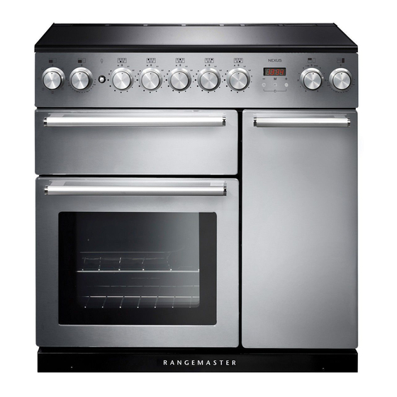
2. Cooker Overview Fig. 2.1 The 90 dual fuel cooker (Fig. 2.1) has the following features: Fig. 2.2 4 hotplate burners and a Wok Burner Control Panel Glide-out Grill™ with 4 position Trivet Multifunction Oven Fan Oven Hotplate Burners The labels by each of the control knobs indicates which area that knob controls. -
Page 10: Wok Burner
The igniter should spark and light the gas. Continue to press Fig. 2.3 in the knob to let the gas through to the burner for about ten seconds. If and when you let go of the control knob or the burner goes out, then the FSD has not been bypassed. -
Page 11: The Griddle
The Griddle Fig. 2.11 The griddle fits the left-hand pan support, front to back (Fig. 2.11). It is designed for cooking food on directly. DO NOT use pans of any kind on it. The griddle surface is non-stick and metal cooking utensils (e.g. spatulas) will damage the surface. Use heat resistant plastic or wooden utensils. -
Page 12: The Glide-Out Grill
The Glide-out Grill™ Fig. 2.15 Open the door and pull the grill pan carriage forward using the handle (Fig. 2.15). The grill has two elements that allow either the whole area of the pan to be heated or just the right-hand half. Adjust the heat to suit by turning the control knob. -
Page 13: The Ovens
The Ovens Function The clock must be set to the time of day before the left To thaw small items in the oven without Defrost hand oven will work. See the following section on ‘The heat Clock’ for instructions on setting the time of day. A full cooking function, even heat Fan oven throughout, great for baking... -
Page 14: Multifunction Oven Functions
Fan Assisted Oven Multifunction Oven Functions Defrost This function operates the fan, circulating air heated by the elements at the top and the base of the oven. This function operates the fan to circulate cold air The combination of fan and conventional cooking only. - Page 15 Operating the Ovens Fig. 2.18 Operating the Multifunction Oven The multifunction oven has two controls: a function selector and a temperature setting knob (Fig. 2.18). Turn the function selector control to a cooking function. Turn the oven temperature knob to the temperature required (Fig. 2.18).
-
Page 16: Using The Clock
Using the Clock Fig. 2.21 You can use the clock to turn the left-hand oven on and off. Note: When using the timer functions, first set the clock as required before setting the oven temperature. The oven can be switched on when the cook symbol [ ] is ArtNo.306-0001 - 3-button clock displayed. - Page 17 To Start and Then Stop the Left-hand Oven Fig. 2.27 Set the left-hand oven to automatically start and stop using a combination of the ‘cook period’ and ‘stop time’. You cannot set a start time directly – this is set automatically by a combination of the ‘cook period’...
-
Page 18: Accessories
Accessories Fig. 2.32 Shelf guard Oven Shelves – Left-hand (Main) Oven The oven shelves (Fig. 2.32) are retained when pulled forward but can be easily removed and refitted. Pull the shelf forward until the back of the shelf is stopped by the shelf stop bumps in the oven sides (Fig. -
Page 19: Cooking Tips
3 Cooking Tips Tips on Cooking with the Timer General Oven Tips If you want to cook more than one dish, choose dishes that The wire shelves should always be pushed firmly to the back require approximately the same cooking time. However, of the oven. -
Page 20: Cooking Table
Position the baking tray with the Fruit 230 mm tin Up to 3½ hours. front edge along the front of the 150 (C/B) oven shelf. Madeira 180 mm 80-90 minutes. 160 (C/B) Small cakes 170 (C/B) 15-25 minutes. Scones 10-15 minutes. -
Page 21: Cleaning Your Cooker Essential Information
ArtNo.045-0004 - Cleaning - 90 induction - tpl glzd dr & GO grill 5. Cleaning Your Cooker Essential Information Fig. 5.1 Isolate the electricity supply before carrying out any thorough cleaning. Allow the cooker to cool. NEVER use paint solvents, washing soda, caustic cleaners, biological powders, bleach, chlorine based bleach cleaners, coarse abrasives or salt. -
Page 22: Grills
Grills Fig. 5.5 The grill pan and trivet should be washed in hot soapy water. Alternatively, the grill pan can be washed in a dishwasher. After grilling meats or any foods that soil, leave to soak for a few minutes immediately after use. Stubborn particles may be removed from the trivet using a nylon brush. -
Page 23: Ovens
Glass Fronted Door Panels Fig. 5.10 The oven door front panels can be taken off so that the glass panels can be cleaned. Move the cooker forward to gain access to the sides (see the ‘Moving the Cooker’ section under ‘Installation’). -
Page 24: Cleaning Table
Cleaning Table Cleaners listed (Table 5.1) are available from supermarkets or electrical retailers as stated. For enamelled surfaces use a cleaner that is approved for use on vitreous enamel. Regular cleaning is recommended. For easier cleaning, wipe up any spillages immediately. Hotplate Part Finish... -
Page 25: Troubleshooting
6. Troubleshooting Hotplate/Cooktop ignition or hotplate burners faulty Food is cooking too slowly, too quickly, or burning Is the power on? If not, there maybe something wrong Cooking times may differ from your previous oven. with the power supply. Check that you are using the recommended Are the sparker (ignition electrode) or burner slots temperatures and shelf positions –... - Page 26 Oven light is not working Fig. 6.1 The bulb has probably burnt out. You can buy a replacement bulb (which is not covered under the warranty) from a good electrical shop. Ask for a 15 W – 230 V lamp, FOR OVENS. It must be a special bulb, heat ArtNo.324-0005 Oven light bulb resistant to 300 °C (Fig.
-
Page 27: Installation
Andi-Co Australia Pty Ltd. 1 Stamford Road, Oakleigh, VIC 3166 Customer Care Tel: 1300 650 020 Email: service@andico.com.au Name of Appliance Nexus 90 Dual Fuel Appliance Serial Number* Fuel Type Dual Fuel Date of Purchase Installer’s Name, Address and Telephone No. -
Page 28: Safety Requirements And Regulations
INSTALLATION Check the appliance is electrically safe and gas sound when you have finished. Safety Requirements and Regulations Provision of Ventilation You must be aware of the following safety requirements & This appliance is not connected to a combustion products regulations. - Page 29 INSTALLATION Check the appliance is electrically safe and gas sound when you have finished. You will need the following equipment to complete the 3 pan supports Wok cradle cooker installation satisfactorily: * Restraining chain and hook: • If the cooker is to be supplied with gas through a flexible hose, a restraining chain and hook MUST be ArtNo.000-0009 Wok ring, cast fitted.
-
Page 30: Positioning The Cooker
130 mm 0.4 mm. Protection should be to a height C of not less than 150 mm ArtNo.090-0025 - 90 classic (gas) door clearances above the hob for the full dimension (width or depth) of the cooking surface area. 3. Side Clearances - Measurement D & E... -
Page 31: Moving The Cooker
INSTALLATION Check the appliance is electrically safe and gas sound when you have finished. Moving the Cooker Fig. 7.1 On no account try and move the cooker while it is plugged into the electricity supply. The cooker is very heavy, so take extra care. We recommend that two people manoeuvre the cooker. -
Page 32: Fitting The Stability Bracket Or Chain
INSTALLATION Check the appliance is electrically safe and gas sound when you have finished. Fitting the Stability Bracket or Chain Fig. 7.5 Unless otherwise stated, a cooker using a flexible gas connector must be secured with a suitable stability device. Stability chain Suitable stability devices are shown in Fig. -
Page 33: Gas Connection
INSTALLATION Check the appliance is electrically safe and gas sound when you have finished. Gas Connection Fig. 7.1 This must be in accordance with the relevant standards. The gas supply needs to terminate with a down-facing threaded fitting ½” connection. The inlet connector is located Gas inlet just below the hotplate level at the rear of the cooker. -
Page 34: Electrical Connection
INSTALLATION Check the appliance is electrically safe and gas sound when you have finished. Electrical Connection Fig. 7.1 This appliance must be installed by a qualified electrician to comply with the relevant regulations (AS/NZS 60335.2.6) and also the local electricity supply company requirements. - Page 35 INSTALLATION Check the appliance is electrically safe and gas sound when you have finished. Fixed Wiring Fig. 7.3 Disconnect from the mains supply. For connection to fixed wiring, i.e. flexible conduit, Remove the electrical terminal cover on the back panel (Fig. 7.3). Remove the M4 screw securing the reducer plates to the conduit box (Fig.
-
Page 36: Final Fitting
INSTALLATION Check the appliance is electrically safe when you have finished. 8. Final Fitting Final Checks Fig. 8-1 Hob Check Check each cooking zone in turn. Be sure to use pans of the correct size and material. Grill Check Turn on the grill control and check that the grill heats up. Oven Check x 2 positions Set the clock as described earlier, and then turn on the ovens. -
Page 37: Conversion To Lp Gas
WARNING – SERVICING TO BE CARRIED OUT ONLY BY AN AUTHORISED PERSON Disconnect from electricity and gas before servicing. Check appliance is safe when you have finished. 9. Conversion to LP Gas Conversion from Natural Gas (1.0 kPa) Fig. 9.1 to LPG X Propane (2.54 kPa) A suitably competent person must perform the conversion. -
Page 38: Set The Governor
WARNING – SERVICING TO BE CARRIED OUT ONLY BY AN AUTHORISED PERSON Disconnect from electricity and gas before servicing. Check appliance is safe when you have finished. Set the Governor Fig. 9.4 Unscrew the governor’s brass top. In the base of the brass top is a plastic snap-in converter device (Fig. -
Page 39: Servicing
WARNING – SERVICING TO BE CARRIED OUT ONLY BY AN AUTHORISED PERSON Disconnect from electricity before servicing. Check appliance is safe when you have finished. 10. Servicing BEFORE SERVICING ANY GAS CARRYING Fig. 10.1 COMPONENTS TURN OFF THE GAS SUPPLY Check the appliance is gas sound after completion of service. - Page 40 WARNING – SERVICING TO BE CARRIED OUT ONLY BY AN AUTHORISED PERSON Disconnect from electricity before servicing. Check appliance is safe when you have finished. 2.3 To Change a Hotplate Burner Injector 2 Hotplate Remove the burner cap and head. Remove the old injector. BEFORE SERVICING ANY GAS CARRYING COMPONENTS, TURN OFF THE GAS SUPPLY.
- Page 41 WARNING – SERVICING TO BE CARRIED OUT ONLY BY AN AUTHORISED PERSON Disconnect from electricity before servicing. Check appliance is safe when you have finished. 3 Controls 4 Grill 3.1. To Replace the Ignition or Light Switch 4.1 To Replace the Grill Controller DISCONNECT FROM THE ELECTRICITY SUPPLY.
- Page 42 WARNING – SERVICING TO BE CARRIED OUT ONLY BY AN AUTHORISED PERSON Disconnect from electricity before servicing. Check appliance is safe when you have finished. Fit the new fan and reassemble in reverse order. Check the Fig. 10.3 operation of the oven. 5.3 To Change the Oven Element DISCONNECT FROM THE ELECTRICITY SUPPLY.
- Page 43 WARNING – SERVICING TO BE CARRIED OUT ONLY BY AN AUTHORISED PERSON Disconnect from electricity before servicing. Check appliance is safe when you have finished. 6 Doors Fig. 10.5 Fig. 10.6 6.1 To Remove the Grill Door Remove the left-hand side panel (see 1.2). Remove the plinth (4 screws) and the central vertical cover (5 screws).
- Page 44 WARNING – SERVICING TO BE CARRIED OUT ONLY BY AN AUTHORISED PERSON Disconnect from electricity before servicing. Check appliance is safe when you have finished. 6.7 To Remove the Tall Oven Door Fig. 10.12 Open the oven door. Supporting the door, remove the 2 screws securing the upper hinge and packing to the cooker front.
-
Page 45: Circuit Diagram
11. Circuit Diagram P095199 P062977 P062362 P028728 P095199 P095199 P095199 The connections shown in the circuit diagram are for single-phase. The ratings are for 230 V 50 Hz. Description Description Grill front switch Ignition switches Grill energy regulator Ignition spark generator Grill element left-hand side Oven light switch Grill element right-hand side... -
Page 46: Technical Data
Natural Gas 1 kPa Propane 2.54 kPa See the appliance badge for test pressures. Dimensions Model NEXUS 90 Dual Fuel Overall height minimum 905 mm maximum 930 mm Overall width 900 mm Overall depth 608 mm excluding handles, 648 mm including handles... -
Page 47: Hotplate Efficiency
Hotplate Efficiency Brand Falcon Model Identification Nexus Size Type Dual Fuel Type of Hob Number of gas burners Auxiliary / Small Burner (EE gas burner) Semi Rapide / Medium Burner (EE gas burner) Semi Rapide / Medium Burner (EE gas burner) -
Page 48: Oven Data
Oven Data Brand Falcon Model identification Nexus Type of oven Electric Mass Number of cavities Left-hand Efficiency Fuel type Electric Cavity type Multifunction Power - conventional Power - forced air convection Volume Litres Energy consumption (electricity) - conventional kWh / cycle 1.08... - Page 49 Note...
- Page 50 Note...
- Page 51 Note...
- Page 52 Cheminee Pty Ltd Showroom: 118 Stanmore Rd, Stanmore NSW 2048 Telephone: 02 9564 2694 Email: sales@Cheminee.com.au www.Cheminee.com.au...
Need help?
Do you have a question about the 90 and is the answer not in the manual?
Questions and answers