Table of Contents
Advertisement
For Modulating, Condensing,
Hot Water Boiler Models:
• MLX-303
• MLX-454
• MLX-606
• MLX-757
• MLX-909
• MLX-1060
• EXT 321
• EXT 481
• EXT 641
• EXT 802
• EXT 962
• EXT 1123
• EXT 1530
• EXT 1912
• EXT 2295
• EXT 2677
• EXT 3060
Revised: 06/05/2013
AERCO International, Inc. • 100 Oritani Dr. • Blauvelt, NY 10913 • Ph: 800-526- 0288
06/05/13
E8 Controller and BCM
Modulex MLX & EXT Boilers
USER MANUAL
Installation, Operation, and Maintenance
E8 Controller for MLX & EXT Series Boilers
Boiler Communications Module (BCM)
.
for MLX and EXT Series Boilers
GF-115-C
OMM-0084_0D
For
Page 1 of 112
Advertisement
Table of Contents

Related Manuals for Aerco E8

Summary of Contents for Aerco E8
- Page 1 E8 Controller for MLX & EXT Series Boilers • EXT 2677 • EXT 3060 Boiler Communications Module (BCM) for MLX and EXT Series Boilers Revised: 06/05/2013 AERCO International, Inc. • 100 Oritani Dr. • Blauvelt, NY 10913 • Ph: 800-526- 0288 06/05/13 Page 1 of 112...
- Page 2 The information contained in this manual is subject to change without notice from AERCO International, Inc. AERCO makes no warranty of any kind with respect to this material, including but not limited to implied warranties of merchantability and fitness for a particular application. AERCO International is not liable for errors appearing in this manual.
-
Page 3: Table Of Contents
Viewing Constant Set Point ................45 5.2.4 Configuring Set Point High and Low Limits Per Outside Temperature Sensor . 45 AERCO International, Inc. • 100 Oritani Dr. • Blauvelt, NY 10913 • Ph: 800-526- 0288 06/05/13 Page 3 of 112... - Page 4 Modbus Software Set-Up ................74 7.7.1 BCM Set-Up for Modbus Operation ..............74 7.7.2 Monitoring and Configuration Only ..............75 AERCO International, Inc. • 100 Oritani Dr. • Blauvelt, NY 10913 • Ph: 800-526- 0288 06/05/13 Page 4 of 112...
- Page 5 E8 Controller Fault Codes ................105 10.2.2 BCM (Boiler Communications Module) Fault Codes ........106 10.2.3 BMM (Burner Management Module) Fault Codes ........108 AERCO International, Inc. • 100 Oritani Dr. • Blauvelt, NY 10913 • Ph: 800-526- 0288 06/05/13 Page 5 of 112...
- Page 6 GF-115-C Modulex E8 Controller and BCM Operations and Maintenance Manual OMM-0084_0D (This page left intentionally blank) AERCO International, Inc. • 100 Oritani Dr. • Blauvelt, NY 10913 • Ph: 800-526- 0288 06/05/13 Page 6 of 112...
-
Page 7: Introduction
E8 Controller and the Boiler Communications Module (BCM) mounted on the front of the unit. Sections 3, 4, 5, 6, and 8 provide descriptions and procedures for the E8 Controller. Sections 7, 9, and 10 provide similar information for the BCM. - Page 8 GF-115-C Modulex E8 Controller and BCM Operations and Maintenance Manual OMM-0084_0D (This page left intentionally blank) AERCO International, Inc. • 100 Oritani Dr. • Blauvelt, NY 10913 • Ph: 800-526- 0288 06/05/13 Page 8 of 112...
-
Page 9: E8 Controller And Bcm Description
The E8 Controller is housed in a compact enclosure measuring 5.7” (145 mm) x 3.9” (100 mm). The Controller is mounted on the front of the Modulex Boiler and contains all of the controls, indicators and displays necessary to adjust, operate and troubleshoot the Modulex Boiler. -
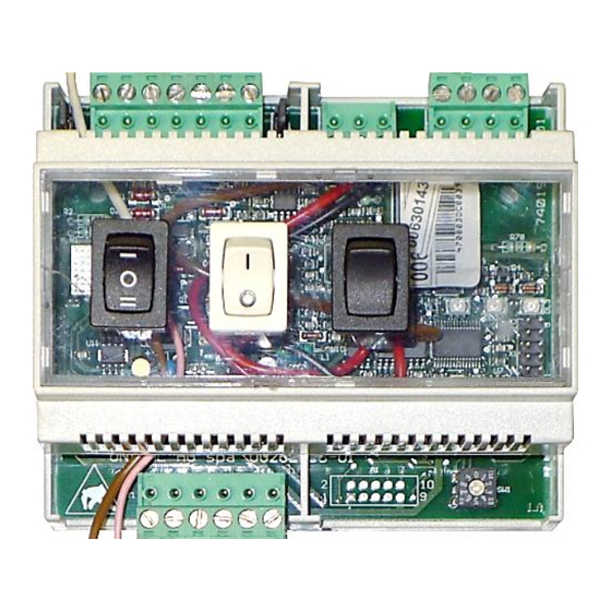
Page 10: Bcm Features And Functions
A photo of the module is shown in Figure 2-2 below. Additional information for the BCM component can be found in Section 7, 9, and 10. Figure 2-2: Modulex BCM (Boiler Communications Module) AERCO International, Inc. • 100 Oritani Dr. • Blauvelt, NY 10913 • Ph: 800-526- 0288 06/05/13 Page 10 of 112... -
Page 11: E8 Controller Operation
Figure 3-1 describes the types of information provided on the LCD display when in NORMAL Mode (door closed). Note that the display in the illustration is only an example, and that an E8 Controller in service will show information appropriate for its configuration. -
Page 12: Heating Mode Selection (In Normal Mode)
3.1.3 MENU Mode Operation (Door Open) Opening the E8 controller hinged door reveals the E8 controls (Figure 3-3) and initiates the AERCO International, Inc. • 100 Oritani Dr. • Blauvelt, NY 10913 • Ph: 800-526- 0288 06/05/13... -
Page 13: Software Menus
Rotary Knob: Used to navigate through menus and parameters or adjust parameters. 3.2 Software Menus Software menus are divided into five main menus, each with a set of sub-menus (Table 3-1). AERCO International, Inc. • 100 Oritani Dr. • Blauvelt, NY 10913 • Ph: 800-526- 0288 06/05/13 Page 13 of 112... - Page 14 Operations and Maintenance Manual OMM-0084_0D The rotary knob on the front of the E8 Controller is used to sequentially cycle through the menus and the sub-menus. Two small arrows at the bottom of the display point to the selected menu and sub-menu name, respectively. Note that some menus and sub-menus are read-only or not available, according to the boiler used and the initial startup configuration.
-
Page 15: Basic Menu/Sub-Menu Navigation And Selection
5. Repeat steps 2, 3 and 4 to view the remaining main menus and their associated sub-menus. The remaining main menus are: USER, TIME PROGRAM, EXPERT, EXPERT HS (Not Applicable to Modulex), and GENERAL. AERCO International, Inc. • 100 Oritani Dr. • Blauvelt, NY 10913 • Ph: 800-526- 0288 06/05/13 Page 15 of 112... -
Page 16: Basic Parameter Navigation, Selection, And Revision
Program Key. The Change LED displayed Displayed will turn off indicating the new value has been saved. value Value Saved! AERCO International, Inc. • 100 Oritani Dr. • Blauvelt, NY 10913 • Ph: 800-526- 0288 06/05/13 Page 16 of 112... -
Page 17: E8 Controller Menus And Sub-Menus
Refer to Section 8 for additional information on functions marked “Not Applicable” in the illustrations and tables provided. AERCO International, Inc. • 100 Oritani Dr. • Blauvelt, NY 10913 • Ph: 800-526- 0288 PR1: 02/23/12 Page 17 of 112... -
Page 18: Display Menu
T-FLOW N-OPT-TIME RETURN SOLAR M/F T-MF1 T-MF2 T-MF3 T-MF4 T-COLLECTOR T-DHW T-DHW L RETURN Figure 4-1: DISPLAY Menu Flow Chart AERCO International, Inc. • 100 Oritani Dr. • Blauvelt, NY 10913 • Ph: 800-526- 0288 06/05/13 Page 18 of 112... - Page 19 Not Applicable T-CIRCL Not Applicable Press Program Key to exit the HOT RETURN WATER Sub-Menu. Table 4-1: DISPLAY Menu Listing (Continued) AERCO International, Inc. • 100 Oritani Dr. • Blauvelt, NY 10913 • Ph: 800-526- 0288 06/05/13 Page 19 of 112...
- Page 20 Currently not used T-DHW Not Applicable Currently not used T-DHW L Not Applicable Press Program Key to exit SOLAR RETURN M/F Sub-Menu. AERCO International, Inc. • 100 Oritani Dr. • Blauvelt, NY 10913 • Ph: 800-526- 0288 06/05/13 Page 20 of 112...
-
Page 21: User Menu
T-LIMIT N HEATSLOPE OPTIM HEAT MAX OPT-TIME ECONO OPTI PC ENABLE RETURN SOLAR M/F RETURN Figure 4-2: USER Menu Flow Chart AERCO International, Inc. • 100 Oritani Dr. • Blauvelt, NY 10913 • Ph: 800-526- 0288 06/05/13 Page 21 of 112... - Page 22 Not Applicable T-DHW 3 Not Applicable BOB-VALUE Not Applicable CIRCL-P- Not Applicable Press Program Key exit HOT WATER Sub- RETURN Menu. AERCO International, Inc. • 100 Oritani Dr. • Blauvelt, NY 10913 • Ph: 800-526- 0288 06/05/13 Page 22 of 112...
- Page 23 RETURN. Press Program Key again to RETURN redisplay SOLAR M/F. Turning the Rotary Knob clockwise will advance thd display to the TIME PROGRAM Menu. AERCO International, Inc. • 100 Oritani Dr. • Blauvelt, NY 10913 • Ph: 800-526- 0288 06/05/13 Page 23 of 112...
-
Page 24: Time Program Menu And Sun-Menus
HTG-PROG 2 MONDAY TUESDAY WEDNESDAY THURSDAY FRIDAY SATURDAY SUNDAY MO-FR SA-SU MO-SU RETURN Figure 4-3: TIME PROGRAM Menu Flow Chart AERCO International, Inc. • 100 Oritani Dr. • Blauvelt, NY 10913 • Ph: 800-526- 0288 06/05/13 Page 24 of 112... -
Page 25: Expert Menu And Sub-Menus
HEATSOURCE 2 STORAGE HS 2 BUFFER RETURN CONTINUED ON SHEET 2 Figure 4-4: EXPERT Menu Flow Chart (Sheet 1 of 2) AERCO International, Inc. • 100 Oritani Dr. • Blauvelt, NY 10913 • Ph: 800-526- 0288 06/05/13 Page 25 of 112... - Page 26 RELAY FUNC 4 T-MF 4 SETP MF4 HYST F15 FUNCTION RETURN Figure 4-4: EXPERT Menu Flow Chart (Sheet 2 of 2) AERCO International, Inc. • 100 Oritani Dr. • Blauvelt, NY 10913 • Ph: 800-526- 0288 06/05/13 Page 26 of 112...
- Page 27 32.0°F – 248.0°F 185.0°F Stop/Start voltage level. Going below/above CURVE 11-UO 0.00V – 10.00V 1.00 this setting will stop/start the Boiler. AERCO International, Inc. • 100 Oritani Dr. • Blauvelt, NY 10913 • Ph: 800-526- 0288 06/05/13 Page 27 of 112...
- Page 28 Not Applicable SEQUENCE 1 Boiler sequence 1 12345678 SEQUENCE 2 Boiler sequence 2 87654321 Table 4-3: EXPERT Menu Listing (Continued) AERCO International, Inc. • 100 Oritani Dr. • Blauvelt, NY 10913 • Ph: 800-526- 0288 06/05/13 Page 28 of 112...
- Page 29 Not Applicable LOAD THROUGH Not Applicable RETURN Press Program Key to exit HOT WATER Sub-Menu. Table 4-3: EXPERT Menu Listing (Continued) AERCO International, Inc. • 100 Oritani Dr. • Blauvelt, NY 10913 • Ph: 800-526- 0288 06/05/13 Page 29 of 112...
- Page 30 Press Program Key to exit HEAT CIRCUIT 1 RETURN (or 2) Sub-Menu. Table 4-3: EXPERT Menu Listing (Continued) FUNCTION DESCRIPTION ENTRY DEFAULT AERCO International, Inc. • 100 Oritani Dr. • Blauvelt, NY 10913 • Ph: 800-526- 0288 06/05/13 Page 30 of 112...
-
Page 31: Available V-Curve Preset Voltage Curves For 0 - 10 Volt Input
5.0 V 4.0 V 0.1 V 68°F 194°F 5.0 V 4.5 EXPERT HS Menu (Not Used) (Not applicable to Modulex boilers) AERCO International, Inc. • 100 Oritani Dr. • Blauvelt, NY 10913 • Ph: 800-526- 0288 06/05/13 Page 31 of 112... -
Page 32: General Menu
The GENERAL Menu contains a DATE/TIME Menu and a SERVICE Menu. 4.6.1 DATE / TIME Menu This Sub-Menu is used to set the time, date, holiday (vacation) schedule and, where AERCO International, Inc. • 100 Oritani Dr. • Blauvelt, NY 10913 • Ph: 800-526- 0288 06/05/13 Page 32 of 112... - Page 33 Set current time (min., hours) 00:00 – 24:00 YEAR Set current year XXXX MONTH Set current month 01 – 12 AERCO International, Inc. • 100 Oritani Dr. • Blauvelt, NY 10913 • Ph: 800-526- 0288 06/05/13 Page 33 of 112...
-
Page 34: Service Menu
Function values. When prompted by a “CODE NO.” display, enter 0000 (four zeros) by pressing the Program Key four (4) times. This will allow function access. AERCO International, Inc. • 100 Oritani Dr. • Blauvelt, NY 10913 • Ph: 800-526- 0288 06/05/13... - Page 35 Controlller. These relays are numbered 00 through 11 and are defined as shown below. CODE NO. Entry is required to access these relays. AERCO International, Inc. • 100 Oritani Dr. • Blauvelt, NY 10913 • Ph: 800-526- 0288 06/05/13 Page 35 of 112...
- Page 36 Table 4-6: SERVICE Menu Listing (Continued) FUNCTION DESCRIPTION REMARKS SENSOR TEST Sub-Menu Flow temperature heating circuit 1 or temperature multifunction 1 AERCO International, Inc. • 100 Oritani Dr. • Blauvelt, NY 10913 • Ph: 800-526- 0288 06/05/13 Page 36 of 112...
-
Page 37: E8 Controller Initial Startup
Initial startup of the Modulex Controller requires a number of one-time entries to be made in the initial INSTALLATION Menu that appears in the display when the E8 controller door is first opened. Table 4-7 on the next page lists the description, entry range, and default entry for all parameter. - Page 38 LANGUAGE Set Language ENGLISH TIME Set current time (min., hrs) 00:00 – 24:00 YEAR Set current year XXXX (4 digits) AERCO International, Inc. • 100 Oritani Dr. • Blauvelt, NY 10913 • Ph: 800-526- 0288 06/05/13 Page 38 of 112...
-
Page 39: Cap/Module Function (Maximum Kilowatts Per Burner)
CAP/MODULE Function (Setting Max. Kw per Burner) 1. Press the Program Key. The display will show CODE NO., requesting the valid code to be AERCO International, Inc. • 100 Oritani Dr. • Blauvelt, NY 10913 • Ph: 800-526- 0288 06/05/13... -
Page 40: Available Settings For Relay Functions 1 - 4
Table 4-8 lists the available Function selections for Multi-Function (MF) Relays 1 thru 4: Table 4-8: Relay 1-4 Functions FUNCTION DESCRIPTION No MF Relay Function Header Pump AERCO International, Inc. • 100 Oritani Dr. • Blauvelt, NY 10913 • Ph: 800-526- 0288 06/05/13 Page 40 of 112... - Page 41 Solid Fuel Boiler Integration (Not Applicable) Solar Integration Return Flow Temperature Increase HS1 Return Flow Temperature Increase HS2 Return Flow Temperature Increase Via Buffer Storage AERCO International, Inc. • 100 Oritani Dr. • Blauvelt, NY 10913 • Ph: 800-526- 0288 06/05/13 Page 41 of 112...
-
Page 42: E8 Operating Mode: Set-Up And Programming
The outdoor air sensor MUST be connected as described in paragraph 5.1.1 above, prior to configuring the Controller for Indoor/Outdoor Reset Mode operation. AERCO International, Inc. • 100 Oritani Dr. • Blauvelt, NY 10913 • Ph: 800-526- 0288 PR1: 02/23/12 Page 42 of 112... - Page 43 Press the Program Key to exit the HTG CIRCUIT 1 sub-menu. Outside Temperature ( F ) Figure 5-1: Heat Slope Diagram AERCO International, Inc. • 100 Oritani Dr. • Blauvelt, NY 10913 • Ph: 800-526- 0288 06/05/13 Page 43 of 112...
-
Page 44: Viewing The Boiler Setpoint
Operations and Maintenance Manual OMM-0084_0D 5.1.3 Viewing the Boiler Setpoint The setpoint temperature setting is viewed in the E8 controller display as shown below. Viewing the Boiler Setpoint Turn the Rotary Knob to the DISPLAY menu. The first sub-menu displayed will be INSTALLATION. -
Page 45: Wiring Connections
180º F whenever the outside temperature is 15º F or below, and 120º F whenever the outside temperature is 60º F or higher. Four parameters must be set in the E8 Controller to accomplish this. They are: HEATSLOPE, MAX T-FLOW, MIN T-FLOW, and MAX T-COLL. -
Page 46: Modulex E8 Controller And Bcm Gf-115-C
Continue scrolling through the HTG CIRCUIT 1 sub-menu until RETURN is displayed. Press the Program Key to exit the HTG CIRCUIT 1 sub-menu. AERCO International, Inc. • 100 Oritani Dr. • Blauvelt, NY 10913 • Ph: 800-526- 0288 06/05/13 Page 46 of 112... - Page 47 Continue scrolling through the HTG CIRCUIT 1 sub-menu until RETURN is displayed. Press the Program Key to exit the HTG CIRCUIT 1 sub-menu. AERCO International, Inc. • 100 Oritani Dr. • Blauvelt, NY 10913 • Ph: 800-526- 0288 06/05/13 Page 47 of 112...
-
Page 48: To 10 Volt Remote Set Point Mode
1 (F-15) and 2 (GND) of connector number 3 (III) on the rear of the Controller. See Section 6 for illustrations and pin-outs of the connectors located on the rear of the Controller. AERCO International, Inc. • 100 Oritani Dr. • Blauvelt, NY 10913 • Ph: 800-526- 0288 06/05/13 Page 48 of 112... -
Page 49: Configuring Remote Signal Source
SOLAR / MF item, the EXPERT HS menu will be displayed. this occurs, slowly turn Rotary Knob counterclockwise until SOLAR / MF is again displayed. AERCO International, Inc. • 100 Oritani Dr. • Blauvelt, NY 10913 • Ph: 800-526- 0288 06/05/13 Page 49 of 112... -
Page 50: Setting The Voltage And Set Point Limits For U1/U2 And T1/T2
10. With the desired high voltage limit displayed, press the Program Key to set the U2 voltage. The red LED will go off. AERCO International, Inc. • 100 Oritani Dr. • Blauvelt, NY 10913 • Ph: 800-526- 0288 06/05/13 Page 50 of 112... -
Page 51: Setting The Curve 11-Uo Voltage
7. Press the Program Key to return to exit the INSTALLATION sub-menu. To view the remote set point temperature, proceed to paragraph 5.3.5. AERCO International, Inc. • 100 Oritani Dr. • Blauvelt, NY 10913 • Ph: 800-526- 0288 06/05/13 Page 51 of 112... -
Page 52: Viewing The Setpoint
ON/OFF switch to the OFF position, then back to the ON position. This is necessary to ensure that the Controller recognizes the added sensor. AERCO International, Inc. • 100 Oritani Dr. • Blauvelt, NY 10913 • Ph: 800-526- 0288 06/05/13... -
Page 53: Configuring The Controller For Dhw With A Tank Sensor
8. With THERM INPUT again displayed and the red LED lit, turn Rotary Knob to change to 00 for sensor operation. 9. Press Program Key to store 00 setting for THERM INPUT. Red LED is off. AERCO International, Inc. • 100 Oritani Dr. • Blauvelt, NY 10913 • Ph: 800-526- 0288 06/05/13 Page 53 of 112... -
Page 54: Setting The Dhw Set Point
Press Program Key to store the temp setting. The red LED will go off. Continue scrolling through the HOT WATER sub-menu until RETURN is displayed. Press the Program Key to exit the sub-menu. AERCO International, Inc. • 100 Oritani Dr. • Blauvelt, NY 10913 • Ph: 800-526- 0288 06/05/13 Page 54 of 112... -
Page 55: Displaying Temperatures Associated With Dhw
2. Press the Program Key to enter the INSTALLATION sub-menu. 3. Turn the Rotary Knob clockwise until T-COLL DES is displayed along with corresponding temperature reading. AERCO International, Inc. • 100 Oritani Dr. • Blauvelt, NY 10913 • Ph: 800-526- 0288 06/05/13 Page 55 of 112... -
Page 56: Dhw Operation Using An Aquastat
Connector “I” and then set the boiler to Standby mode ( ). To set the boiler to Standby mode, close the swing-down front panel door of the E8 and turn the wheel counterclockwise until the Standby symbol ( ) is displayed. With terminals 3 and 4 closed, the Standby symbol, and others in the display, will be blinking. - Page 57 GF-115-C Modulex E8 Controller and BCM Operations and Maintenance Manual OMM-0084_0D (This page left intentionally blank) AERCO International, Inc. • 100 Oritani Dr. • Blauvelt, NY 10913 • Ph: 800-526- 0288 06/05/13 Page 57 of 112...
-
Page 58: Connection Diagrams
F15 = 0-10V input/light sensor/Room sensor for heating circuit 2 (2+3) F17 = Pulse counter for output measurement (1+2) Data line CAN bus (3+4) Power supply CAN bus AERCO International, Inc. • 100 Oritani Dr. • Blauvelt, NY 10913 • Ph: 800-526- 0288 PR1: 02/23/12 Page 58 of 112... -
Page 59: Power Terminal Assignments
A11 = Collector pump 1 (speed controlled) multifunction relay 4 6.1 Power Terminal Assignments Plug 2 [II] Plug 6 [VI] AERCO International, Inc. • 100 Oritani Dr. • Blauvelt, NY 10913 • Ph: 800-526- 0288 06/05/13 Page 59 of 112... -
Page 60: Sensor Terminal Assignments
THE PRIMARY PUMP (COLLECTOR PUMP 2) MUST BE WIRED TO RELAY A10. 6.2 Sensor Terminal Assignments Connector 7 [VII] Connector 1 [I] Connector 5 [V] AERCO International, Inc. • 100 Oritani Dr. • Blauvelt, NY 10913 • Ph: 800-526- 0288 06/05/13 Page 60 of 112... - Page 61 Operations and Maintenance Manual OMM-0084_0D 6.2 Sensor Terminal Assignments (Continued) Connector 8 [VIII] => PT 1000 Sensor Connector 3 [III] Connector 9 [IX] AERCO International, Inc. • 100 Oritani Dr. • Blauvelt, NY 10913 • Ph: 800-526- 0288 06/05/13 Page 61 of 112...
-
Page 62: Boiler Communications Module (Bcm)
• BCM provides a fault relay which energizes when any fault condition occurs in the Modulex Boiler. • BCM serves as a Back-up Controller in the event that the primary E8 Controller fails. • BCM can be selected as the Primary Controller instead of the E8. - Page 63 Modulex Boiler 10-Pos. Rotary on the input Modbus or Ebus Network. Switch AERCO International, Inc. • 100 Oritani Dr. • Blauvelt, NY 10913 • Ph: 800-526- 0288 06/05/13 Page 63 of 112...
-
Page 64: Bcm Fault Relay
BCM. However, if the cause of the fault has not been corrected, the Fault Relay will again be activated. SWITCHES Figure 7-3: BCM Fault Relay & Reset Switch Wiring AERCO International, Inc. • 100 Oritani Dr. • Blauvelt, NY 10913 • Ph: 800-526- 0288 06/05/13 Page 64 of 112... -
Page 65: Bcm Configured As Back-Up Controller
When the BCM is configured as the Back-Up Controller for the E8, it will assume control of the Modulex Boiler if the E8 fails. In the event of an E8 Controller failure, the BCM will operate the Modulex Boiler in the Constant Setpoint Mode (default setpoint = 180°F [82°C]). The primary Boiler Pump must also be wired to the BCM so it will run when the BCM assumes control in the Back-Up Mode. -
Page 66: Bcm Configured As Primary Controller Utilizing Modbus
NOTE: When the BCM is configured as the primary controller, the E8 will display the fault code “E200”. The BCM can be configured as the Primary Controller, instead of the E8, when it is connected to a Modbus Network. However, the E8 must be disconnected from the e-Bus connection on the BCM Board (see Paragraph 7.4.3). -
Page 67: Physical Modbus Rs485 Wiring
Modbus wiring connections are made at terminals 1 and 2 of BCM connector Y2 as shown in Figure 7-7. BCM FRONT VIEW Figure 7-7: BCM Modbus (RS485) Connections AERCO International, Inc. • 100 Oritani Dr. • Blauvelt, NY 10913 • Ph: 800-526- 0288 06/05/13 Page 67 of 112... -
Page 68: Disconnecting The E8 From The E-Bus On The Bcm Board
If the BCM was retrofitted in the field utilizing Technical Service Bulletin 2007-07, refer to this bulletin and disconnect CBL 24 from Connector VII on the E8 Controller. However, if the Modulex Boiler was shipped with the BCM factory-installed, it will contain a 3-position switch mounted above the BCM (Figure 7-8). -
Page 69: Aerco Bms Ii/Acs Master To Bcm Slave Wiring Connections
7.4.4 AERCO BMS II/ACS Master to BCM Slave Wiring Connections. The AERCO BMS II/ACS contains a RS232 port for connection to an EMS/BAS or personal computer. In addition, the BMS II/ACS contains a RS485 port for connection to the BCM’s Modbus input. -
Page 70: Bcm Controller Terminating Resistor And Bias
1K ohm resistor as shown in Figure 7-9. DO NOT install this bias resistor if the controlling Master is an AERCO BMS II or ACS. Bias will be provided by the BMS II/ACS DIP switches. The last unit in the chain must be energized (even if disabled) to enable bias. - Page 71 Also, twisted-pair wiring shields should only be terminated at the controlling Master for the Modbus Network. AERCO International, Inc. • 100 Oritani Dr. • Blauvelt, NY 10913 • Ph: 800-526- 0288 06/05/13 Page 71 of 112...
- Page 72 GF-115-C Modulex E8 Controller and BCM Operations and Maintenance Manual OMM-0084_0D AERCO International, Inc. • 100 Oritani Dr. • Blauvelt, NY 10913 • Ph: 800-526- 0288 06/05/13 Page 72 of 112...
- Page 73 GF-115-C Modulex E8 Controller and BCM Operations and Maintenance Manual OMM-0084_0D AERCO International, Inc. • 100 Oritani Dr. • Blauvelt, NY 10913 • Ph: 800-526- 0288 06/05/13 Page 73 of 112...
-
Page 74: Modbus Software Set-Up
See Section 9 of this document and Section 2 of GF-124 for Modbus points for the BCM and BMS II/ACS. Figure 7-12: Location of BCM Address Selection Switch SW1 AERCO International, Inc. • 100 Oritani Dr. • Blauvelt, NY 10913 • Ph: 800-526- 0288 06/05/13 Page 74 of 112... -
Page 75: Monitoring And Configuration Only
A multiple Modulex boiler plant offers inherent standby protection and ease of installation along with longevity. In a multiple boiler plant of over two boilers, the use of an AERCO Boiler Management System II (BMS II) Model 5R5-384/AERCO Control System (ACS) is recommended for maximum efficiency and flexibility of operator control. -
Page 76: Sequence Of Operation (Example: Four-Modulex Boiler Installation)
Refer to BMS II Operations and Maintenance Manual GF-124/ACS Manual GF-131, and Product Spec BMS-II for details. AERCO International, Inc. • 100 Oritani Dr. • Blauvelt, NY 10913 • Ph: 800-526- 0288 06/05/13 Page 76 of 112... - Page 77 GF-115-C Modulex E8 Controller and BCM Operations and Maintenance Manual OMM-0084_0D (This page intentionally blank) AERCO International, Inc. • 100 Oritani Dr. • Blauvelt, NY 10913 • Ph: 800-526- 0288 06/05/13 Page 77 of 112...
-
Page 78: E8 Controller Menu Listings
Temperature of storage tank 3 (e.g. solar T-STORAGE 3 pool-heating) MODGRAD Modulation degree of HS (BUS) Press Program Key to exit RETURN INSTALLATION Sub-Menu. AERCO International, Inc. • 100 Oritani Dr. • Blauvelt, NY 10913 • Ph: 800-526- 0288 PR1: 02/23/12 Page 78 of 112... - Page 79 Upper hot water temperature Currently not used T-DHW L Hot water temperature in-feed RETURN Press Program Key to exit SOLAR M/F Sub-Menu. AERCO International, Inc. • 100 Oritani Dr. • Blauvelt, NY 10913 • Ph: 800-526- 0288 06/05/13 Page 79 of 112...
-
Page 80: User Menu
Circulation Pump for Domestic Hot CIRCL-P-DHW 00, 01 (OFF/ON) 00 = OFF Water Press Program Key exit HOT WATER RETURN Sub-Menu. AERCO International, Inc. • 100 Oritani Dr. • Blauvelt, NY 10913 • Ph: 800-526- 0288 06/05/13 Page 80 of 112... - Page 81 Press Program Key again to redisplay RETURN SOLAR M/F. Turning the Rotary Knob clockwise will advance thd display to the TIME PROGRAM Menu. AERCO International, Inc. • 100 Oritani Dr. • Blauvelt, NY 10913 • Ph: 800-526- 0288 06/05/13 Page 81 of 112...
-
Page 82: Time Program Menu
See prev. OFF: 22:00h RETURN Press Program Key to exit CIRCL sub-menu Table 8-3: TIME PROGRAM Menu Sub-Menus and Parameters (Continued) AERCO International, Inc. • 100 Oritani Dr. • Blauvelt, NY 10913 • Ph: 800-526- 0288 06/05/13 Page 82 of 112... - Page 83 22:00h Press Program Key to exit HOTW – RETURN PROG sub-menu. Table 8-3: TIME PROGRAM Menu Sub-Menus and Parameters (Continued) AERCO International, Inc. • 100 Oritani Dr. • Blauvelt, NY 10913 • Ph: 800-526- 0288 06/05/13 Page 83 of 112...
- Page 84 HTG PROG 1 above. Press Program Key to exit HTG – PROG 2 sub- RETURN menu. AERCO International, Inc. • 100 Oritani Dr. • Blauvelt, NY 10913 • Ph: 800-526- 0288 06/05/13 Page 84 of 112...
-
Page 85: Expert Menu
CURVE 11-UO 0.00V – 10.00V 1.00 this setting will stop/start the Boiler. Table 8-4: EXPERT Menu Sub-Menus and Parameters (Continued) AERCO International, Inc. • 100 Oritani Dr. • Blauvelt, NY 10913 • Ph: 800-526- 0288 06/05/13 Page 85 of 112... - Page 86 SEQUENCE 1 Boiler sequence 1 12345678 SEQUENCE 2 Boiler sequence 2 87654321 Table 8-4: EXPERT Menu Sub-Menus and Parameters (Continued) AERCO International, Inc. • 100 Oritani Dr. • Blauvelt, NY 10913 • Ph: 800-526- 0288 06/05/13 Page 86 of 112...
- Page 87 01 = ON 00 = OFF LOAD THROUGH 00 (OFF) 01 = ON Table 8-4: EXPERT Menu Sub-Menus and Parameters (Continued) AERCO International, Inc. • 100 Oritani Dr. • Blauvelt, NY 10913 • Ph: 800-526- 0288 06/05/13 Page 87 of 112...
- Page 88 0 hours) 48°F Heating slope distance. 32°F – 194°F SLOPE OFFSET (N/A) Table 8-4: EXPERT Menu Sub-Menus and Parameters (Continued) AERCO International, Inc. • 100 Oritani Dr. • Blauvelt, NY 10913 • Ph: 800-526- 0288 06/05/13 Page 88 of 112...
-
Page 89: General Menu
Press Program Key to exit SOLAR M/F RETURN Sub-Menu. 8.5 GENERAL Menu The GENERAL Menu contains a DATE/TIME Sub-Menu and a SERVICE Sub-Menu. AERCO International, Inc. • 100 Oritani Dr. • Blauvelt, NY 10913 • Ph: 800-526- 0288 06/05/13 Page 89 of 112... -
Page 90: Date / Time Sub-Menu
The SERVICE Menu contains all the test and diagnostic functions/values required for Customer Service Engineers to troubleshoot the equipment in a timely manner. AERCO International, Inc. • 100 Oritani Dr. • Blauvelt, NY 10913 • Ph: 800-526- 0288 06/05/13 Page 90 of 112... - Page 91 Heat generator /header temperature Outside temperature Table 8-6: GENERAL Menu / SERVICE Sub-Menus and Parameters (Continued) FUNCTION DESCRIPTION REMARKS SENSOR TEST Sub-Menu AERCO International, Inc. • 100 Oritani Dr. • Blauvelt, NY 10913 • Ph: 800-526- 0288 06/05/13 Page 91 of 112...
- Page 92 DO NOT USE RESET EXPERT DO NOT USE RESET T-PRG 00 DO NOT USE RETURN Exit level using Program Key AERCO International, Inc. • 100 Oritani Dr. • Blauvelt, NY 10913 • Ph: 800-526- 0288 06/05/13 Page 92 of 112...
- Page 93 GF-115-C Modulex E8 Controller and BCM Operations and Maintenance Manual OMM-0084_0D (This page left intentionally blank) AERCO International, Inc. • 100 Oritani Dr. • Blauvelt, NY 10913 • Ph: 800-526- 0288 06/05/13 Page 93 of 112...
-
Page 94: Bcm Modbus And Address Assignments
No more than 1.5 character times of silence between received and transmitted characters. Heartbeat Timeout: Adjustable (0 or 1 – 240 seconds) AERCO International, Inc. • 100 Oritani Dr. • Blauvelt, NY 10913 • Ph: 800-526- 0288 PR1: 02/23/12 Page 94 of 112... -
Page 95: Bcm Controller Standard Holding Register Assignments
The Read Only, Write Only or Read/Write status for each function in Table 9-4 is shown in the Default/Comments column. AERCO International, Inc. • 100 Oritani Dr. • Blauvelt, NY 10913 • Ph: 800-526- 0288 06/05/13 Page 95 of 112... - Page 96 0 = No action (Read/Write) 1023 Pump Control 1 = Switch OFF 2 = Switch ON 1030 Error/Reset enum (0x5A) (Read/Write) AERCO International, Inc. • 100 Oritani Dr. • Blauvelt, NY 10913 • Ph: 800-526- 0288 06/05/13 Page 96 of 112...
- Page 97 Target Setpoint 100°C) (Value x 10) DHW Maximum 32°F to 212°F (0°C to (Read Only) 1019 Setpoint 100°C) (Value x 10) AERCO International, Inc. • 100 Oritani Dr. • Blauvelt, NY 10913 • Ph: 800-526- 0288 06/05/13 Page 97 of 112...
- Page 98 100°C) (Value x 10) BMM #n Actual Modulation 0 – 100% 2n08 (Read Only) Level (n = 0 – 7) AERCO International, Inc. • 100 Oritani Dr. • Blauvelt, NY 10913 • Ph: 800-526- 0288 06/05/13 Page 98 of 112...
- Page 99 1 – 10 minutes 3006 Pump Over-run Time (Read/Write) 5 min. Table 9-4: BCM Standard Holding Register Address Mapping (Continued) AERCO International, Inc. • 100 Oritani Dr. • Blauvelt, NY 10913 • Ph: 800-526- 0288 06/05/13 Page 99 of 112...
- Page 100 0x5A: Test mode request messages are executed only in Test mode. Table 9-4: BCM Standard Holding Register Address Mapping (Continued) AERCO International, Inc. • 100 Oritani Dr. • Blauvelt, NY 10913 • Ph: 800-526- 0288 06/05/13 Page 100 of 112...
- Page 101 Mode [0, 1] bit 4: DL1 [OFF, ON] bit 5: eBUS TX bit 6: eBUS-1 TX bit 7: eBUS Supply [OFF, AERCO International, Inc. • 100 Oritani Dr. • Blauvelt, NY 10913 • Ph: 800-526- 0288 06/05/13 Page 101 of 112...
-
Page 102: E8, Bcm, And Bmm Fault Codes
Fault codes are displayed in the upper right area of the LCD display on the E8 Controller as shown in Figure 10-1. -
Page 103: Processing And Clearing Fault Codes
7. Monitor the display to ensure no other Fault Codes appear. 8. Resume normal operation after all faults have been cleared. AERCO International, Inc. • 100 Oritani Dr. • Blauvelt, NY 10913 • Ph: 800-526- 0288 06/05/13 Page 103 of 112... -
Page 104: Fault Codes And Descriptions
BMM (Burner Management Module): These fault codes are shown in Table 10-4. In order to derive the correct error code from that displayed in the E8 Controller display, use Table 10-1 below to determine the working error code. To use the table, identify the displayed number from the first column, identify the affected module from the second column, apply the formula from the third column, and identify the Error Table to reference from the fourth column. -
Page 105: E8 Controller Fault Codes
Modulex E8 Controller and BCM Operations and Maintenance Manual OMM-0084_0D 10.2.1 E8 Controller Fault Codes The table below lists the fault codes and fault descriptions associated with the E8 Controller. Table 10-2: E8 Controller Fault Codes FAULT CODE FAULT DESCRIPTION... -
Page 106: Bcm (Boiler Communications Module) Fault Codes
OMM-0084_0D FAULT CODE FAULT DESCRIPTION Communication Fault E8: Address 0 and 1 on BUS. IDs BUS 0 and 1 may not bee used E 90 simultaneously E 91 E8: BUS ID used. The set BUS ID is already in use by another device... - Page 107 Subtract 65280 from Displayed Number = BCM Fault Code in Table 10-3 65280 Table 10-3: BCM Fault Codes CODE DESCRIPTION EFFECT CORRECTION RESET AERCO International, Inc. • 100 Oritani Dr. • Blauvelt, NY 10913 • Ph: 800-526- 0288 06/05/13 Page 107 of 112...
-
Page 108: Bmm (Burner Management Module) Fault Codes
10.2.3 BMM (Burner Management Module) Fault Codes The table below lists the fault codes and troubleshooting tips associated with the BMM. Table 10-4: BMM Fault Codes AERCO International, Inc. • 100 Oritani Dr. • Blauvelt, NY 10913 • Ph: 800-526- 0288 06/05/13 Page 108 of 112... - Page 109 Table 10-4: BMM Fault Codes (Continued) CODE DESCRIPTION EFFECT CORRECTION RESET Return Sensor All burners Check return sensor or AUTOMATIC AERCO International, Inc. • 100 Oritani Dr. • Blauvelt, NY 10913 • Ph: 800-526- 0288 06/05/13 Page 109 of 112...
- Page 110 If off. wiring OK then change BMM. Table 10-4: BMM Fault Codes (Continued) CODE DESCRIPTION EFFECT CORRECTION RESET AERCO International, Inc. • 100 Oritani Dr. • Blauvelt, NY 10913 • Ph: 800-526- 0288 06/05/13 Page 110 of 112...
- Page 111 VAC) Low Water Flow. Burners Check water flow or Low water flow AUTOMATIC turned OFF. check switch. switch activated. NOTES: AERCO International, Inc. • 100 Oritani Dr. • Blauvelt, NY 10913 • Ph: 800-526- 0288 06/05/13 Page 111 of 112...
-
Page 112: 06/05/13 Aerco International, Inc. • 100 Oritani Dr. • Blauvelt, Ny 10913 • Ph: 800-526- 0288
GF-115-C Modulex E8 Controller and BCM Operations and Maintenance Manual OMM-0084_0D © AERCO International, Inc., 2012 AERCO International, Inc. • 100 Oritani Dr. • Blauvelt, NY 10913 • Ph: 800-526- 0288 06/05/13 Page 112 of 112...
Need help?
Do you have a question about the E8 and is the answer not in the manual?
Questions and answers