Table of Contents
Advertisement
Quick Links
E N G L I S H
Rev 1.4
HV Diagnostics, Inc
North and South America
271 Rope Mill Pkwy, Ste2
Woodstock, GA 30188
USA
Tel. +1 678-445-2555
Fax +1 678-445-2557
www.hvdiagnostics.com
sales@hvdiagnostics.com
HV Diagnostics S.à.r.l.
Africa, Asia, Australia,
Middle East
www.hvdsa.com
TD30
User Manual
Portable Tan Delta Measurement System
Advertisement
Table of Contents

Summary of Contents for HV Diagnostics TD30
- Page 1 TD30 User Manual E N G L I S H Rev 1.4 HV Diagnostics, Inc North and South America 271 Rope Mill Pkwy, Ste2 Woodstock, GA 30188 Tel. +1 678-445-2555 Fax +1 678-445-2557 www.hvdiagnostics.com sales@hvdiagnostics.com HV Diagnostics S.à.r.l. Africa, Asia, Australia, Middle East www.hvdsa.com...
- Page 2 User Manual Rev 1.4 Page 2 HV Diagnostics...
- Page 3 Should this instrument be used for other applications and purposes not covered herein, please contact HV Diagnostics to validate its suitability. This manual, all of its contents and the instruments specifications are subject to change without notice Windows®, Windows 2000®, Windows XP®, Windows 7®...
-
Page 4: Table Of Contents
General Description ................10 Technical Specifications* ...............10 Materials ....................11 Hardware Description ................13 Connecting up the TD30 Instrument ............16 Software TD ControlCenter ..............17 10 Instrument Care ..................24 Appendix A: Software Installation Procedure ‘TD ControlCenter’....25 Appendix B: Bluetooth® Setup and Config Procedure ........26 Rev 1.4... -
Page 5: Forward
To assure that the workplace is safe and • Management messages and information has all required equipment regarding general product description. To assure that HVA and TD operators are • qualified technicians To assure that operators fulfil their • responsibilities HV Diagnostics Page 5 Rev 1.4... -
Page 6: Documentation Conventions
Red outlined circle with red diagonal line: Used to indicate forbidden practices. The described handling practice must not be carried out! Blue circle with white exclamation mark: Used to indicate recommended precautionary measures or a situation that can lead to property damage. Rev 1.4 Page 6 HV Diagnostics... -
Page 7: Legal Considerations
User Manual Legal Considerations Warranty HV Diagnostics provides a one-year warranty from the original purchase date of instrument for all necessary parts and labor. This warranty is void in the event of abuse, incorrect operation or use, unauthorized modification or repairs, or failure to perform the specified maintenance as indicated in this operation manual. -
Page 8: Safety
The LED signal colors on the TD system indicate a TD value / range or equipment status condition. These LED lights signals in no way indicate the presence or absence of high voltage and the TD30 should be considered energized at all times when connected to a potential voltage source like a HVA test system. -
Page 9: Introduction
Tan Delta testing enables the cable test engineer to detect insulation defects before the cable fails in service. The TD30 is a versatile tan delta measuring system that is directly connected to the HVA series of VLF test systems from HV Diagnostics. The tan delta test results of the test object can now be easily measured and recorded and the results stored on a standard PC or Laptop for analysis, trending or quality control. -
Page 10: General Description
11 lbs / 5 kg Dimensions Length x Diameter: 11” x 3” / 28 cm x 8 cm Technical Specifications are subject to change. HV Diagnostics reserves the right to modify values in accordance with future HVA development. Rev 1.4... -
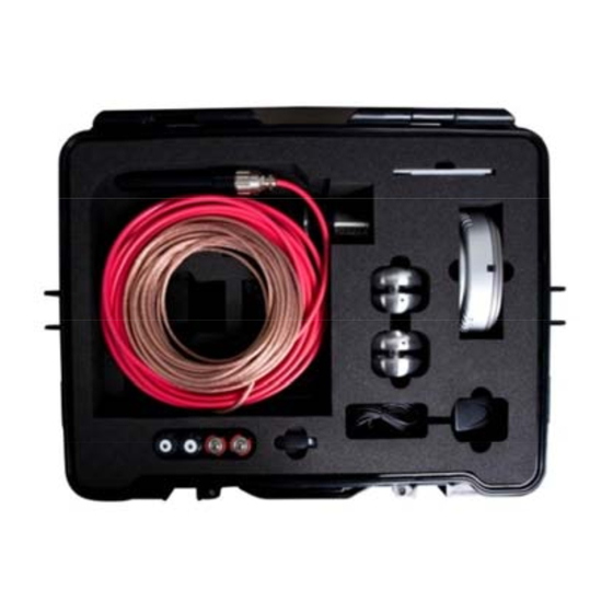
Page 11: Materials
Materials Shipment Content Items included upon delivery of the HVA are listed below. The * marking specifies items that are country specific. For inquiries, please contact HV Diagnostics. For inquiries, please contact HV Diagnostics. Part No. Item Description 700 003... - Page 12 User Manual C Batteries 1.5 V Battery Cap Hooks TD head inserts Alligator Clip TD30 Manual TD Software: TD Control Center (On USB Flash Drive) Rev 1.4 Page 12 HV Diagnostics...
-
Page 13: Hardware Description
Depending on the application, the 3-Pod “Sputnik” Stand which is supplied can be used to ensure proper isolation. High Voltage Cable High Voltage connection cable that links the TD30 to the HVA generator. High Voltage Plug TD30 Plug directly into HVA30 HV output plug socket. - Page 14 User Manual The Head of the TD30 system with the Cap removed showing the Battery compartment and the ON / OFF switch. Pos. Item Description TD system control By removing the Tan Delta head cap the main switch and the battery housing can be accessed.
- Page 15 User Manual LED 1 – High Limit TD LED 2 – Medium Limit TD LED 3 – Low Limit TD LED 4 – Battery Low LED 5 – TD30 Status Pos. Item Description LED 1 Signal High TD A flashing signal here indicates a TD level that (RED) is higher than the HIGH TD setting.
-
Page 16: Connecting Up The Td30 Instrument
Shielded Cable The Ground Cable of the TD30 should be connected to the station ground (or to the HVA as long as the HVA is grounded). In the case of a cable, this can be the concentric neutral / ground shield / ground wire. -
Page 17: Software Td Controlcenter
Handhelds come with integrated built-in Bluetooth® capability and the supplied Bluetooth® Dongle with the TD30 will normally not be required under these circumstances. In case where Bluetooth® is already available or integrated into a PC, follow the user manual for that device to correctly configure the Bluetooth®... - Page 18 User Manual TD ControlCenter Main Screen Rev 1.4 Page 18 HV Diagnostics...
- Page 19 The Title Bar shows connection status information like the serial of the TD system that is paired to the current PC, the Battery Status information if a low signal if detected. A battery Low status will also be visible on the battery status LED present on the TD30 (see above). 2. Information Selection Tabs Use these Tabs to switch between the various information you want to view.
- Page 20 TD System Sleep Places the connected TD System into Power Save Mode. This is useful if the TD30 is not going to be used for TD measurements for some extended period of time and the user wants to conserve battery life.
- Page 21 The user can store certain fields that are not likely to change from one test to another as default start-up fields. These fields are then easily and automatically inserted into any new test reports. Fields stored: Station, Company, Region and Operator HV Diagnostics Page 21 Rev 1.4...
- Page 22 Cable/Line ID field. 12 Currently Measuring…… Phase Selection The phase that is currently being tested by the TD30 needs to be selected. All new measurement data will be put into the corresponding report phase section (tab). If the operator changes the phase during an active TD measurement, the change will only occur when the current TD voltage block is finished to avoid splitting up of the respective TD measurement data block.
- Page 23 Use this function to make a copy the currently shown TD diagram into the Windows Clipboard. It can then be easily put into many other applications (like Word, Excel) by selecting Paste in the target program. HV Diagnostics Page 23 Rev 1.4...
-
Page 24: Instrument Care
• Humidity: 5-85% non-condensing • Maintenance and Repairs NOTICE Authorized personnel only! Repairs and maintenance should only be performed by authorized HV Diagnostics’ personnel. One yearly inspection by authorized HV Diagnostics’ personnel is recommended. Rev 1.4 Page 24 HV Diagnostics... -
Page 25: Appendix A: Software Installation Procedure 'Td Controlcenter
The content of this folder is now shown, locate the file “Setup TD ControlCenter” and • double click (this file can also be named “Setup TD ControlCenter.exe” or just “Setup.exe”). Setup will start now proceed as described above. HV Diagnostics Page 25 Rev 1.4... -
Page 26: Appendix B: Bluetooth® Setup And Config Procedure
Appendix B: Bluetooth® Setup and Config Procedure A Bluetooth USB dongle is shipped with every TD30 system. This dongle is tested to work with the TD unit and can be used if your Computer/Notebook has no built in integrated Bluetooth Hardware. - Page 27 Setup.exe in the driver folder. Due to possible technologically changes in drivers and the Windows operating system, certain messages shown below may vary slightly to what you may find on your computer. Driver Setup Start Screen HV Diagnostics Page 27 Rev 1.4...
- Page 28 User Manual Accept License agreement Choose Driver Software Destination. We suggest to use the defaults. Rev 1.4 Page 28 HV Diagnostics...
- Page 29 User Manual Begin Installation Installation has started HV Diagnostics Page 29 Rev 1.4...
- Page 30 Plug the dongle into a free USB port. The windows Hardware Installation will now run and some further information windows will appear. Please wait until the Hardware Detection has finished. This screen will then disappear automatically. Rev 1.4 Page 30 HV Diagnostics...
- Page 31 Installation of Bluetooth support on your Computer. Other information messages may appear. Please wait until the Installation completes. Installation of Bluetooth support finished. The above mentioned white on Blue “B”-Bluetooth icon now appears in the system tray. HV Diagnostics Page 31 Rev 1.4...
- Page 32 Double click on the Bluetooth icon in the system tray or the “My Bluetooth Places” icon on your desktop to bring up the configuration wizard: Initial Bluetooth configuration (only has to be done once) Rev 1.4 Page 32 HV Diagnostics...
- Page 33 User Manual Type in the name and type of your computer Start Configuration HV Diagnostics Page 33 Rev 1.4...
- Page 34 Check or uncheck those Bluetooth services you want to use. If you only want to set up for TD communication you can uncheck all except the “Bluetooth Serial Port” which is all the TD30 requires. Bluetooth Serial Port Configuration. Leave as suggested. Take note of the serial port number.
- Page 35 User Manual Press Skip to tell the system that you will connect to the TD system at a later stage. Finished Initial Setup of Bluetooth Support. HV Diagnostics Page 35 Rev 1.4...
- Page 36 WLAN or other RF devices, try moving the TD system closer to your computer if you cannot get a “pairing” connection from following the procedure below. Setup the Communication Port to connect to the TD30 Start to set up a communication port to the TD system by double-clicking on the “My Bluetooth Places”...
- Page 37 Select “I want to find a specific Bluetooth device …” to find the TD system All available Bluetooth devices are listed. TD systems are shown with the last 6 digits of the Serial number. Select the TD unit you want to connect to. HV Diagnostics Page 37 Rev 1.4...
- Page 38 Pair the device. Type in the PIN code “welcome” and press “Initiate Pairing”. A message “No Com port available” may be appear. Just quit with ok. Check the “TDCommunication” service to use. A message to configure the port will appear. Rev 1.4 Page 38 HV Diagnostics...
- Page 39 User Manual Leave default setting for this port. Make note of it. You can use either Secure or Unsecured Connection. Successful Setup of communication port! HV Diagnostics Page 39 Rev 1.4...
- Page 40 To establish the connection and to fix the settings of the COM-port you have to perform a initial connection to the TD unit. This is also verifies a correct setup. Double click the TD System icon. Connecting to the TD System Rev 1.4 Page 40 HV Diagnostics...
- Page 41 It is also possible to switch off the TD system and the connection will automatically be closed. The System is now configured and you can start working with the TD ControlCenter. You will use the given COM-Port number to set in the ControlCenter and press the connect button. HV Diagnostics Page 41 Rev 1.4...
- Page 42 Setup the Communication Port Start to set up and allocate a communication port to the TD system by double-clicking on the Bluetooth icon in the system tray. Bluetooth Devices, press Add to start Rev 1.4 Page 42 HV Diagnostics...
- Page 43 Check Device is switched on and ready to discover All available Bluetooth devices are listed. TD systems are shown with the last 6 digits of the Serial number. Select the TD unit you want to connect to. HV Diagnostics Page 43 Rev 1.4...
- Page 44 User Manual Select “Use Passkey from documentation” and enter “welcome” to use as key Windows connects to the TD System and installs the relevant drivers. Rev 1.4 Page 44 HV Diagnostics...
- Page 45 This number is used by the TD ControlCenter to communicate with the TD unit. You can use the 3 page of the manual to write down this Configuration Com Port number for later reference purposes. HV Diagnostics Page 45 Rev 1.4...
- Page 46 User Manual The System is now configured. You can start working with the TD ControlCenter. Use the given COM-Port number in the TD ControlCenter and press the connect button. Rev 1.4 Page 46 HV Diagnostics...
- Page 47 User Manual HV Diagnostics Page 47 Rev 1.4...
Need help?
Do you have a question about the TD30 and is the answer not in the manual?
Questions and answers