Table of Contents
Advertisement
Quick Links
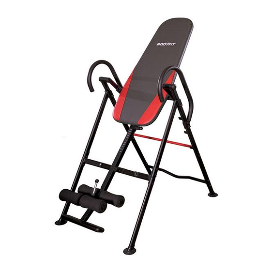
Inversion Table
Model ISA 2300
Version 1-20147
CAUTION:
WARNING: DO NOT USE THIS
INVERSION TABLE WITHOUT A
PHYSICIAN'S APPROVAL
It is recommended that Inverting
upside down be supervised.
Do not let children use the
inversion table unsupervised.
Read all instructions carefully
before using.
Tighten all bolts before using
equipment.
Leave adequate space to
properly invert.
Questions/ Comments
PLEASE DO NOT CONTACT THE
STORE FOR PARTS OR
SERVICE QUESTIONS
Extreme Products Group is committed to
providing the very best of quality and
customer satisfaction for all of the products
we distribute. If for any reason , you are
dissatisfied with the product you have
purchased or need assistance in any way,
please do not hesitate to contact our
knowledgeable support staff as follows:
Phone:623-888-6379
Email: service@extremeproductsgroup.com
Web: www.extremeproductsgroup.com
Photo may differ from actual product
Mon.-Fri 9:00 am – 5:00 pm Phoenix Time
1
Advertisement
Table of Contents

Summary of Contents for Extreme Products Group ISA 2300
- Page 1 PLEASE DO NOT CONTACT THE STORE FOR PARTS OR SERVICE QUESTIONS Extreme Products Group is committed to providing the very best of quality and customer satisfaction for all of the products we distribute. If for any reason , you are...
- Page 2 Extreme Products Group Customer Service Number at 623-888-6379 for assistance in the repair or replacement of the product or any covered part. Extreme Products Group will repair or replace, at its own option, the product or any covered part, except that this warranty does not cover damage caused by accident ( including transit) , or repairs or attempted repairs by any person not authorized by Extreme Products Group, or by vandalism, misuse, abuse, or alteration.
-
Page 3: Parts Listing
Parts Listing * For Any Parts Required, DO NOT CALL TECHNICAL SUPPORT. Please visit our web site: www.extremeproductsgroup.com... - Page 4 Parts Listing * For Any Parts Required, DO NOT CALL TECHNICAL SUPPORT. Please visit our web site: www.extremeproductsgroup.com...
-
Page 5: Exploded View
Exploded View * For Any Parts Required, DO NOT CALL TECHNICAL SUPPORT. Please visit our web site: www.extremeproductsgroup.com * For Any Parts Required, DO NOT CALL TECHNICAL SUPPORT. Please visit our web site: www.extremeproductsgroup.com... - Page 6 Base Frame and Handlebar Assembly STEP 1- Base Frame Unpack Base frame from Carton. Attach (1L) Upper Left A- Frame into (2L) Front Left Base Frame and (3L) Right Rear Base Frame. Repeat for Right Side of Frame. Connect the Rear Section of the A-Frame using 2 Bolts (18) 2 Washers (16), and 2 Nuts (17) on the left and right side.
-
Page 7: Handlebar Assembly
Handlebar Assembly STEP 2 Attach the Handlebars (6) to the Rear Base Frame (1L) and (1R) Connect using 2 Bolts (19) 2 Washers (16) and 2 Nuts (17) on each side as shown. Insert Safety Pin (21) into Right Side of A- Frame to prevent frame from folding TIGHTEN ALL BOLTS AT THIS TIME... - Page 8 Backrest Assembly to Base Frame Right Attached the Backrest Frame Rotational (7) to the Left and Right Brackets Rotational Brackets using 2 MUST POINT TOWARDS FLOOR bolts (20) 2 Washers (16) and Left 2 Nuts (17) on each side Rotational Brackets MUST POINT TOWARDS FLOOR...
- Page 9 Connecting Backrest Pad to Backrest Assembly Connect Backrest Pad (8) to the Backrest Assembly (7) using 4 Bolts (9) 2 Washers (16) TIGHTEN ALL BOLTS AT THIS TIME * For Any Parts Required, DO NOT CALL TECHNICAL SUPPORT. Please visit our web site: www.extremeproductsgroup.com...
- Page 10 STEP 4-Body Height Adjustment Tube and Rollers Install Foot Rest Plate (13) into Height Adjustment Tube (10) using 3 Screws (27) 3 Washers (16) Extend out Front Roller Tube 11 and position as indicated. Attached Rear Roller Tube (12) through hole in Height Adjustment Tube ( 10) and connect using Bolt (28), Spacer (29) , Washer (16) and Nut (17).
-
Page 11: Step 5-Final Assembly
STEP 5-Final Assembly Slide Completed Lower Ankle Roller and Height Adjustment Selector Rod into the receptacle of the Backrest Support Assembly. Make Sure Height Adjustment Knob Bolt ( 23) snaps into place, and is then secured with Safety Pin (23). Position Inversion Bar into 1 of the 3 Rear Position... - Page 12 To reduce the risk of serious injury, read all important precautions instructions and warnings in this manual before using the Inversion System. Extreme Products Group assumes no responsibility for personal injury or property damage sustained by or through the use of the Inversion System.
- Page 13 USAGE GUIDELINES- Securing Feet and Ankles WARNING: ALWAYS WEAR ATHLETIC SHOES WITH LACES TIGHT TO HELP SECURE YOUR FEET IN THE INVERSION SYSTEM, AND FOR FOOT PROTECTION WHILE EXERCISING. ALWAYS MAKE SURE THAT THE ANKLE LOCK IS SECURED SNUGLY AGAINST YOUR ANKLES AND THAT THE LONG KNOB IS FULLY TIGHTENED BEFORE YOU USE THE INVERSION SYSTEM Step 1- Expand the front rollers by pulling up on the...
-
Page 14: Usage Guidelines
USAGE GUIDELINES Finding the Proper Height and Weight Adjustment With head flat on back pad, slowly raise one arm up toward the ceiling. If the bed starts to invert backward, the height adjustment should be correct. If the bed does not start to invert, adjust the center slider arm upward one position at a time, until the bed starts to invert backward. - Page 15 Bodyfit is Distributed by The Sports Authority though an agreement with Extreme Products Group 6635 W. Happy Valley Rd Suite A-104, #213 Phoenix, AZ 85310 Phone: 623-888-6379 Fax: 623-434-9100 Email: service@extremeproductsgroup.com For All parts requests, please visit our web site at www.extremeproductsgroup.com...
Need help?
Do you have a question about the ISA 2300 and is the answer not in the manual?
Questions and answers