Table of Contents
Advertisement
Quick Links
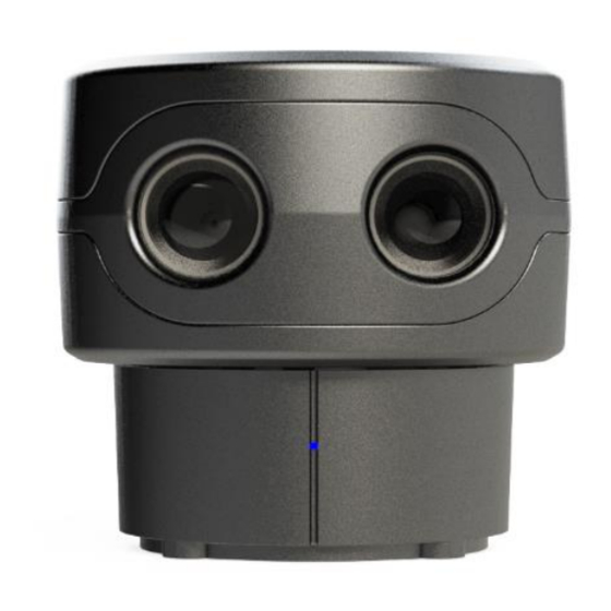
sweep v1.0
✓ Cost efficient design
✓ Operates in full sunlight
✓ Low power consumption
✓ Wide field of view
✓ Small footprint
✓ Simple serial connectivity
✓ Long Range
CAUTION
This device contains a component which emits laser radiation.
This laser product is designated Class 1 in accordance with IEC
60825-1:2007 during all operating modes. This means that the
laser is safe to look at with the unaided eye, however it is
advisable to not look directly into the beam when in use.
When connecting a Sweep sensor to a 5VDC power source, it
should be limited to a maximum of 8A as defined in EN 60950-1,
sub clause 2.5, Table 2B.
Documentation Revision Information
Rev
Date
Changes
0.98
4/18/2017
Updated communication protocol
0.97
03/29/2017
Updated mechanical drawings
0.9
12/19/2016
Initial Release
Laser Safety ....................................................... 0
Power Safety ..................................................... 0
Specifications ..................................................... 2
Physical ............................................................. 2
Electrical ........................................................... 2
Measurement Performance ............................. 2
Field of View ..................................................... 2
Measurement Error Test Data .......................... 2
Overview of Interfaces ....................................... 3
Connector ......................................................... 3
Status LED ......................................................... 4
Mounting Features and Orientation ................... 4
Mounting and Vibration Considerations .......... 4
Mounting Sweep with Bottom Removed ......... 4
Ingress Protection Rating .................................. 4
Enclosure Window Design ................................ 5
Theory of Operation ........................................... 5
Distance Measurement..................................... 5
Angle Measurement ......................................... 5
Applications ....................................................... 5
Visualizer Overview ............................................ 5
Serial Protocol Specification ............................... 6
Data Encoding and Decoding ............................ 6
Communication Format .................................... 6
General Communication Packet Structure .......... 6
Definition of terms: ........................................... 7
DS - Start data acquisition................................. 8
DX - Stop data acquisition ................................. 9
MZ - Motor Ready ............................................ 9
MS - Adjust Motor Speed ............................... 10
MI - Motor Information ................................. 10
LR - Adjust LiDAR Sample Rate ....................... 11
LI - LiDAR Information .................................... 11
IV - Version Details .......................................... 12
ID - Device Info ................................................ 12
RR - Reset Device ............................................ 12
Appendix: ......................................................... 13
Advertisement
Table of Contents

Related Manuals for Scanse Sweep V1

Summary of Contents for Scanse Sweep V1
-
Page 1: Table Of Contents
Mounting Features and Orientation ....4 Mounting and Vibration Considerations ..4 Mounting Sweep with Bottom Removed ..4 Ingress Protection Rating ........4 sweep v1.0 Enclosure Window Design ........ 5 Theory of Operation ........... 5 ✓ Cost efficient design Distance Measurement........ -
Page 2: Specifications
Specification Value Range 40 m (131ft) (75% reflective target) Resolution 1 cm (0.4 in) Range in Centimeters Update Rate Up to 1075Hz (see (75% reflective target) “Theory of Operation”) Figure 3, Sweep Accuracy Graphs Copyright ©2014-2017 Scanse LLC - www.scanse.io... -
Page 3: Connector
1.25 mm (0.049 in.) pitch. Connector 26-30 AWG crimp SSHL-002T- terminal socket connector P0.2 Wire UL 1061 26 AWG N/A N/A stranded copper DRAWINGS ARE NOT TO SCALE Figure 5, Sweep Connector Diagram Copyright ©2014-2017 Scanse LLC - www.scanse.io... - Page 4 It is recommended that Sweep be placed inside a protective transparent enclosure if Figure 9, Sweep Internal Mounting Features it will be used in dusty or wet environments. ALL DIMENSIONS ARE IN MM, DRAWINGS ARE NOT TO SCALE Copyright ©2014-2017 Scanse LLC - www.scanse.io...
- Page 5 You can download the Sweep visualizer at www.scanse.io/downloads The purpose of the Scanse visualizer is to provide a way to quickly evaluate Sweep’s performance in your application/environment. For some applications, like surveying, our visualizer can be used to take quick measurements between range data points within a scan.
- Page 6 (2 bytes) (2 bytes) (1 byte) (1 byte) Response with parameter echoed Command Symbol Parameter Line Feed Status Sum of Status Line Feed (2 bytes) (2 bytes) (LF) (2 bytes) (1 byte) (1 byte) Copyright ©2014-2017 Scanse LLC - www.scanse.io...
-
Page 7: Serial Protocol Specification
Usually these indicate a failure to process the command, often for valid reasons. Sum of Status: 1 byte of data used to check for corrupted transmission. See Appendix for instructions for authenticating receipts. Copyright ©2014-2017 Scanse LLC - www.scanse.io... - Page 8 Signal strength : Signal strength of current ranging measurement. Larger is better. 8-bit unsigned int, range: 0-255 • Checksum: Calculated by adding the 6 bytes of data then dividing by 255 and keeping the remainder. (Sum of bytes 0-5) % 255 ... Use the instructions in the Appendix. Copyright ©2014-2017 Scanse LLC - www.scanse.io...
- Page 9 The MZ command allows the user to repeatedly query the motor speed state until the return code indicates the motor speed has stabilized. After the motor speed is noted as stable, the user can safely send commands like DS or MS. Copyright ©2014-2017 Scanse LLC - www.scanse.io...
- Page 10 This does not mean that the motor speed is stabilized yet. (HOST -> SENSOR) (SENSOR -> HOST) Speed Code (2 bytes) See previous “MS – Adjust Motor Speed” command for a breakdown of the possible Speed Codes. Copyright ©2014-2017 Scanse LLC - www.scanse.io...
- Page 11 Returns current LiDAR Sample Rate Code in ASCII: (HOST -> SENSOR) (SENSOR -> HOST) Speed(Hz) (2 bytes) Sample Rate Code (2 byte ASCII code, ie: ‘02’ = 0x3032): • ‘01’ = 500-600Hz • ‘02’ = 750-800Hz • ‘03’ = 1000-1075Hz Copyright ©2014-2017 Scanse LLC - www.scanse.io...
- Page 12 115200 0500 Resets the device. Green LED indicates the device is resetting and cannot receive commands. When the LED turns blue, the device has successfully reset. (HOST -> SENSOR) (SENSOR -> HOST) No Response Copyright ©2014-2017 Scanse LLC - www.scanse.io...
-
Page 13: Appendix
//assume dataBlock holds the DATA_BLOCK byte array, //such that indices 1 & 2 correspond to the two azimuth bytes angle_int (dataBlock[2] << (dataBlock[1]); degree ( (angle_int >> ( (angle_int & 16.0 ) ); Copyright ©2014-2017 Scanse LLC - www.scanse.io... - Page 14 //calculate the sum of the specified status or msg bytes calculatedSum for(let 0; i < 6; i++){ //add each status byte to the running sum calculatedSum dataBlock[i]; calculatedSum calculatedSum 255; expectedSumVal dataBlock[6]; return calculatedSum expectedSumVal; Copyright ©2014-2017 Scanse LLC - www.scanse.io...
Need help?
Do you have a question about the Sweep V1 and is the answer not in the manual?
Questions and answers