Advertisement
Quick Links
Advertisement

Summary of Contents for King Ultrasonic CO KWL3215
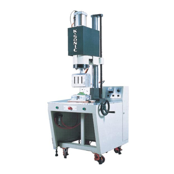
- Page 1 Ultrasonic Plastic Welder User’s Manual KWL3215 KWL4215 King Ultrasonic CO., LTD.
- Page 2 Safety Notes The machine should be installed on a firm, flat surface. The earth wires of the machine should be securely connected. Do not modify any parts or lines of the machine without the consent of King Supersonic Co., Ltd. Do not use accessories that are not supplied by King Supersonic Co., Ltd.
- Page 3 Name and Function of Body Components: Air Circuit Diagram III. Operation Guidelines: Notes: Operating Principles: Mechanism Principles: Installation Procedures: Mold Adjustment Procedure Ultrasonic Welding Steps Basic Steps for Using Ultrasonic Plastic Welder of King Ultrasonic CO., LTD. IV. Circuit Diagram Welding Problems and Solutions...
- Page 4 I. Specifications Model Frequency Power Welding Compressed Dimension Power Source Weight Capability 3200W ψ220m/m KWL-3215 15KHz 9KG/cm 750*990*2060 220V/15A3P 300KG 4200W ψ250m/m KWL-4215 15KHz 9KG/cm 750*990*2060 220V/20A3P 300KG II. Component Description (1) Component Position (A) Position of Body Components 1. Triplet Set 2.
- Page 5 Drop Buffer Adjusting Screw: Adjust the drop buffer rate of the welding head (at the point 24mm from the end of the drop stroke). Rotate it clockwise to increase the buffer rate or rotate it anti-clockwise to decrease the buffer rate. Vibrating Cylinder: Accommodate and secure the oscillator and spacer to connect the welding head.
- Page 6 14. Welding timer: The time during which the ultrasonic wave is transmitting. 15. Curing Timer: The time from stopping the ultrasonic transmission to when the vibrating cylinder rises. During this time, the plastic is curing from its molten state with the pressure being exerted on the work-piece.
- Page 7 convenience. 23. Emergency Rise Button: Upon pushing this button at any time, the ultrasonic transmission stops and the vibrating cylinder returns to its original position immediately. 24. Power Switch: Upon turning on this switch, the machine will be energized, indicators will light up, and fans will run.
- Page 8 (1) Wrong Grounding Ground Equipment A Equipment B Ultrasonic Equipment C (2) Wrong Grounding Equipment A Equipment B Ultrasonic Equipment C Ground Equipment A Ground Equipment B Ultrasonic Equipment C 31. Power Cord: AC220V three phase (3P). 32. Iron Male Connector: Air pressure is delivered to the connector.
- Page 9 Position of Components Position of Components Position of Components...
- Page 10 Position of Components...
- Page 11 組件位置圖 Position of Components...
- Page 12 1. Copper Connector 1/4 2. Quick Bend 1/4 *Ø8 3. Quick Bend 1/4 *Ø8 4. Water filter FB300 5. Iron Male Connector 6. Oil Filler FL300 7. Pressure Governor R04-200 8. Pressure Gauge 1/4 9. Quick Bend 1/4 *Ø8 10. Quick Bend 1/4 *Ø8 Solenoid Valv 空 壓 回 路 圖...
- Page 13 III. Operation Guidelines: (1) Notes: 1. During operation, do not open the door of the electrical box to avoid high-voltage injury. 2. Carry out adequate grounding to avoid electrostatic charge. 3. During operation, both hands should be placed around the button and keep away from the welding head to avoid injury.
- Page 14 ※ 6. Before operation, always check the sonic wave to ensure the resonance between the vibration system and oscillator, especially after the welding head is replaced or the amplitude is changed. (5) Mold Adjustment Procedure To acquire the largest throughput, the distance between the welding head and the work-piece should be as short as possible, but a sufficient space is required for the placement and removal of the work-piece.
- Page 15 Plastic material Shape and size of the work-piece Distance between the contact surface and the welding head Horizontal thickness of the sidewall and joint face Cleaning and finishing of the surface (such as painting, electroplating and mold release agent) Ambient temperature of the work-piece Mold adjustment preciseness 10.
- Page 16 (6) Operating Procedures Ultrasonic Welding Steps 1. Select vibration amplitude, level 2. Adjust the frequency 3. Align the welding head, work-piece, and base contact surface 1. Set the welding pressure 2. Set the rise and drop speed of the stroke 3.
- Page 17 IV (Oscillation Wiring Diagram) Ω...
- Page 18 IV (Control Wiring Diagram) Control System Wiring Diagram...
- Page 19 V (Welding problems and solutions) (1) Welding Problems Causes Solutions Surface damage The shape of the welding head is Check the work-piece size. damaged. Check the variation of the work-piece between the molds. The welding time is too long. Increase the pressure or amplitude to reduce the welding time.
- Page 20 Problems Causes Solutions Internal parts The amplitude is too high. Reduce the amplitude. damaged during The welding time is too long. Increase the pressure or amplitude to welding. The work-piece absorbs too much reduce the welding time. energy. Inappropriate assembly of Adjust the buffer or delay time.
- Page 21 (2) Riveting Problems Causes Solutions The riveting point is The rivet bore is too big or Reduce the size of the uneven and dented. the rivet is too small. rivet bore or increase the height of the rivet. Residual flash appears The rivet bore is too small or Increase the size of the around...
- Page 22 (3) Embedding Problems Causes Solutions Plastic parts crack after The time of the ultrasonic wave Reduce the delay-on time. embedding. transmission is too late or the Decrease the pressure. ultrasonic waves do not transmit. Reduce the buffer rate. Too many obstructions and unmber of hole too many.
- Page 23 Problems Causes Solutions Inappropriate embedded time ultrasonic Increase the welding time. depth. transmission is insufficient. The Decrease the drop rate. drop rate is faster than the plastic melting rate. The embedded object is too long. The pressure or energy efficiency is bad.
- Page 24 Problems Causes Solutions Operators should shift The noise level is too high. Noise might not be prevented due regularly wear to the friction occurring between protectors. metal pieces in ultrasonic welding Emit ultrasonic wave before welding head applications. touches the object to be embedded.
- Page 25 Quality Policy Excellent Quality Customer Satisfaction Striving for Perfection Profit Sharing King Ultrasonic CO., LTD. Head Office : No.8, Wu-Kung 5 Rd., Wu-Ku Industrial Park, Taipei 242, Taiwan TEL: 886-2-22980299(16 Lines) FAX:886-2-22980399 Taichung Branch: No.22-2,Ln.171,Wenxin S.6th Rd.,Nantun Dist.,Taichung City408,Taiwan TEL: 886-4-2223301-2223308 FAX:886-4-2223270...
Need help?
Do you have a question about the KWL3215 and is the answer not in the manual?
Questions and answers