
Related Manuals for Radcal Dynalyzer III

Summary of Contents for Radcal Dynalyzer III
- Page 1 RAPIDOSE DYNALYZER Dynalyzer III Digital Display/Printer Rapid Measurements – with a super small footprint detector USER GUIDE OPERATION MANUAL...
- Page 3 Costs to return-ship by ground to customers will be paid by Radcal if the repairs are warranty-applicable. Radcal shall not be held liable for damages or delays caused by defects beyond making repairs or furnishing replacement parts, not shall Radcal be liable for any defective material replaced without Radcal’s consent during the period of this warranty.
-
Page 4: Table Of Contents
Dynalyzer – Digital Display/Printer OPERATION MANUAL Contents Important ................................2 Introduction ................................2 Description................................. 2 Construction ..............................3 Measured Quantities ............................. 3 Predicted Maximum mAs Reading Inaccuracy for Selected Exposure Times ..........6 Calculated Quantities ............................ 6 Operation ................................8 Operation ................................ -
Page 5: Important
Dynalyzer – Digital Display/Printer OPERATION MANUAL Important READ THIS MANUAL Serious measurement errors may result from improper use of this equipment or improper interpretation of readings. Introduction As an element of the Dynalyzer system, the Digital Display embodies a wide range of x-ray measurement features for rapid calibration, compliance testing, and troubleshooting. -
Page 6: Construction
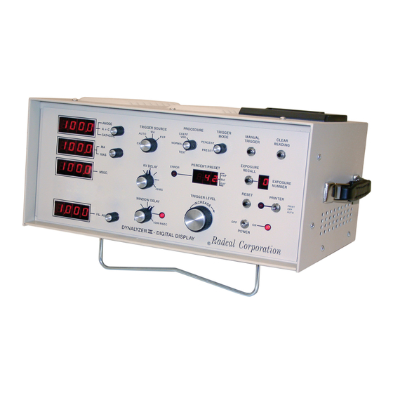
Dynalyzer – Digital Display/Printer OPERATION MANUAL Construction A louvered aluminum cover with a luggage type handle encloses a rugged, yet lightweight aluminum chassis. Four 4-digit LED displays show all x-ray parameters in a clear logical arrangement and are protected, along with the front panel controls, by an extension of the cover. The rear panel contains a selectable line voltage cable receptacle, bulkhead receptacles for connection to the Dynalyzer II or III High Voltage Unit and BNC connectors for an auxiliary oscilloscope. - Page 7 Dynalyzer – Digital Display/Printer OPERATION MANUAL Figure 1: Typical Dynalyzer III System...
- Page 8 [192] dimension in inches [mm] High Voltage Unit Interconnect Figure 3: Rear Panel Description Socket - Accepts cable from Dynalyzer II or Dynalyzer III High Voltage Unit ERROR CODES H-V UNIT 000 SYSTEM O.K. EXT TRIG 901 10,000 VDC OUT-VCO U22 ANLG BD.
-
Page 9: Predicted Maximum Mas Reading Inaccuracy For Selected Exposure Times
Dynalyzer – Digital Display/Printer OPERATION MANUAL Predicted Maximum mAs Reading Inaccuracy for Selected Exposure Times RAD Mode (1 mV/mA as selected at High Voltage Unit) Exposure Time mAs Displayed Displayed 1,000 2,621* (msec) ± 0.17 ± 0.71 ± 3.1 ± 6.1 ±... - Page 10 3. The low mA (Fluoro range) is selectable at the Dynalyzer III HVU. With this range selected, the normal scale factor (1 mA = 1 mV) is multiplied by 20 (1 mA = 20 mV).
-
Page 11: Operation
Dynalyzer – Digital Display/Printer OPERATION MANUAL Figure 4:... -
Page 12: Operation
Dynalyzer – Digital Display/Printer OPERATION MANUAL Operation Specifications Printer Characters 116 characters, 5 x 7 font, 24 characters per line Data Per Line 24 characters per line Duty Cycle Continuous Print Rate 1.7 lines per second Input Buffer 6900 characters Paper Advance Paper feed switch Plain paper, 2-1/4”W x 1,6”... -
Page 13: Triggering Sources
Voltage Selection Triggering Sources There are several different methods of starting or triggering the Dynalyzer III Display measurement and analysis functions for an x-ray exposure. The TRIGGER SOURCE switch is used to determine which trigger source is to be used. -
Page 14: External Trigger
In the AUTO mode the Digital Display provides one second updates of the filament current to enable adjustment of the filament current controls. The Dynalyzer III High Voltage Unit filament current sensor is frequency compensated from 20- 20,000 Hz. This enables the system to work with conventional x-ray generators, and with certain CT generators employing high frequency power supplies. -
Page 15: Trigger Level
Dynalyzer – Digital Display/Printer OPERATION MANUAL Using the Preset mode allows triggering on the absolute level of kV or mA, which is displayed directly in the Percent/Preset window. In this mode the Display eliminates any fluctuation in the trigger level during a series of exposures. The effects of pre-trigger pulses, x-ray tube instability, and other transient phenomena will not change the trigger level. - Page 16 Dynalyzer – Digital Display/Printer OPERATION MANUAL Figure 7: Effect of 50% Trigger Level on Exposure Time ERROR AREA 50% TRIGGER LEVEL MEASURED READ TIME 50% level= 2.7 ms. error Single-phase generators should produce time values that are multiples of 1/120 of a second (8.33 milliseconds).
- Page 17 Dynalyzer – Digital Display/Printer OPERATION MANUAL Figure 9: Use of 75% Trigger Level for Three-Phase Exposure Time Measurement 75% TRIGGER LEVEL The mA trigger capability is especially useful in grid pulsed systems, as pulsed-grid tubes such as sine units are, in general, operated with a constant potential capacitor bank or a continuously present three phase voltage.
-
Page 18: Kv Measurement Delay
Dynalyzer – Digital Display/Printer OPERATION MANUAL Figure 10: Use of mA Trigger to Compensate for Cable Capacitance CABLE CHARGE TRIGGER END OF EXPOSURE By triggering on tube current, the exposure time will be read when the emission stops. Units with biased focal spots will also tend to exhibit this phenomenon. -
Page 19: Fluoroscopic Current Measurements (0-20 Ma)
Dynalyzer III High Voltage Unit. Window Delay Mode Operation A new feature has been added to the Dynalyzer III which enables viewing any 20 msec part of the first second of an exposure. To use this function, the WINDOW DELAY control must be turned ON past its minimum delay time of 50 msec, at which point the associated LED lights to indicate that the Window Mode is selected. - Page 20 Dynalyzer – Digital Display/Printer OPERATION MANUAL Falling load mA waveforms are illustrated below. Turn the WINDOW DELAY control to display more than 50 msec in the MSEC display. Figure 12: Use of Window Delay with Continuous Falling Load Generators WINDOW DELAY TO 1 SEC.
-
Page 21: Exposure Number Window And Recall Button
Dynalyzer – Digital Display/Printer OPERATION MANUAL can then be set to 100 msec, at which point the regulator action will begin. Make a second exposure. By comparing mA, the operation of the regulator can be judged. In this mode, in order to be sure that a long exposure coupled with a long delay does not interfere with the measurement of the following exposure, wait at least 8 seconds between. - Page 22 Dynalyzer – Digital Display/Printer OPERATION MANUAL COV values to within 0.004 of the actual computational value can be attained. The formula employed in the internal calculation is as follows: (x - x) Where: • C = Coefficient of Variation • X = Mean value of displayed parameter •...
-
Page 23: Applications
Dynalyzer – Digital Display/Printer OPERATION MANUAL Applications Typical Operating Sequence The setup of the High Voltage Unit is described in separate data and must be read before operating the unit. It is extremely important that the high voltage cable connections be properly made and that proper insulating oil or grease be used. -
Page 24: Recommended Procedure For Verification Of X-Ray Equipment Calibration
Dynalyzer – Digital Display/Printer OPERATION MANUAL Recommended Procedure for Verification of X-ray Equipment Calibration X-Ray Tube KVP (A + C), Transformer Balance A & C, and Exposure Timer Verification 1. Connect both anode and cathode sections of the Dynalyzer High Voltage Unit in series with the transformer. - Page 25 Dynalyzer – Digital Display/Printer OPERATION MANUAL Figure 14: Grid-Pulsed System Measurements kVp READ EXPOSURE TIME PEAK DETECTOR...
-
Page 26: Printer
Dynalyzer – Digital Display/Printer OPERATION MANUAL Printer Loading Paper into the Printer To load a new roll of printer paper do the following: 1. Remove the printer cover by sliding it towards the rear of the Dynalyzer. 2. Remove the paper roll spindle by lifting up on its right end (facing the front of the Dynalyzer). 3. -
Page 27: Output Port
Dynalyzer – Digital Display/Printer OPERATION MANUAL Output Port RS232 Port Settings This RS232 port is set to transmit data using the following parameters: • 2400 baud • No parity checking • 8 data bits • 1 stop bit The receiving equipment should be set to the same parameters. The Dynalyzer will output data on the RS232 port with the exact same format as the printer data.
Need help?
Do you have a question about the Dynalyzer III and is the answer not in the manual?
Questions and answers